service interval DODGE NEON 1999 Service Repair Manual
[x] Cancel search | Manufacturer: DODGE, Model Year: 1999, Model line: NEON, Model: DODGE NEON 1999Pages: 1200, PDF Size: 35.29 MB
Page 2 of 1200
LUBRICATION AND MAINTENANCE
CONTENTS
page page
GENERAL INFORMATION................... 1
JUMP STARTING, TOWING AND HOISTING.... 7MAINTENANCE SCHEDULES................ 3
GENERAL INFORMATION
INDEX
page page
GENERAL INFORMATION
CLASSIFICATION OF LUBRICANTS........... 1
FLUID CAPACITIES....................... 2
INTERNATIONAL SYMBOLS................ 1INTRODUCTION......................... 1
PARTS AND LUBRICANT
RECOMMENDATIONS.................... 1
GENERAL INFORMATION
INTRODUCTION
Service and maintenance procedures for compo-
nents and systems listed in Schedule ± A or B can be
found by using the Group Tab Locator index at the
front of this manual. If it is not clear which group
contains the information needed, refer to the index at
the back of this manual.
There are two maintenance schedules that show
proper service based on the conditions that the vehi-
cle is subjected to.
Schedule ±A, lists scheduled maintenance to be
performed when the vehicle is used for general trans-
portation.
Schedule ±B, lists maintenance intervals for vehi-
cles that are operated under the conditions listed at
the beginning of the Maintenance Schedule section.
Use the schedule that best describes your driving
conditions.
Where time and mileage are listed, follow the
interval that occurs first.
PARTS AND LUBRICANT RECOMMENDATIONS
When service is required, Chrysler Corporation
recommends that only Mopartbrand parts, lubri-
cants and chemicals be used. Mopar provides the
best engineered products for servicing Chrysler Cor-
poration vehicles.
INTERNATIONAL SYMBOLS
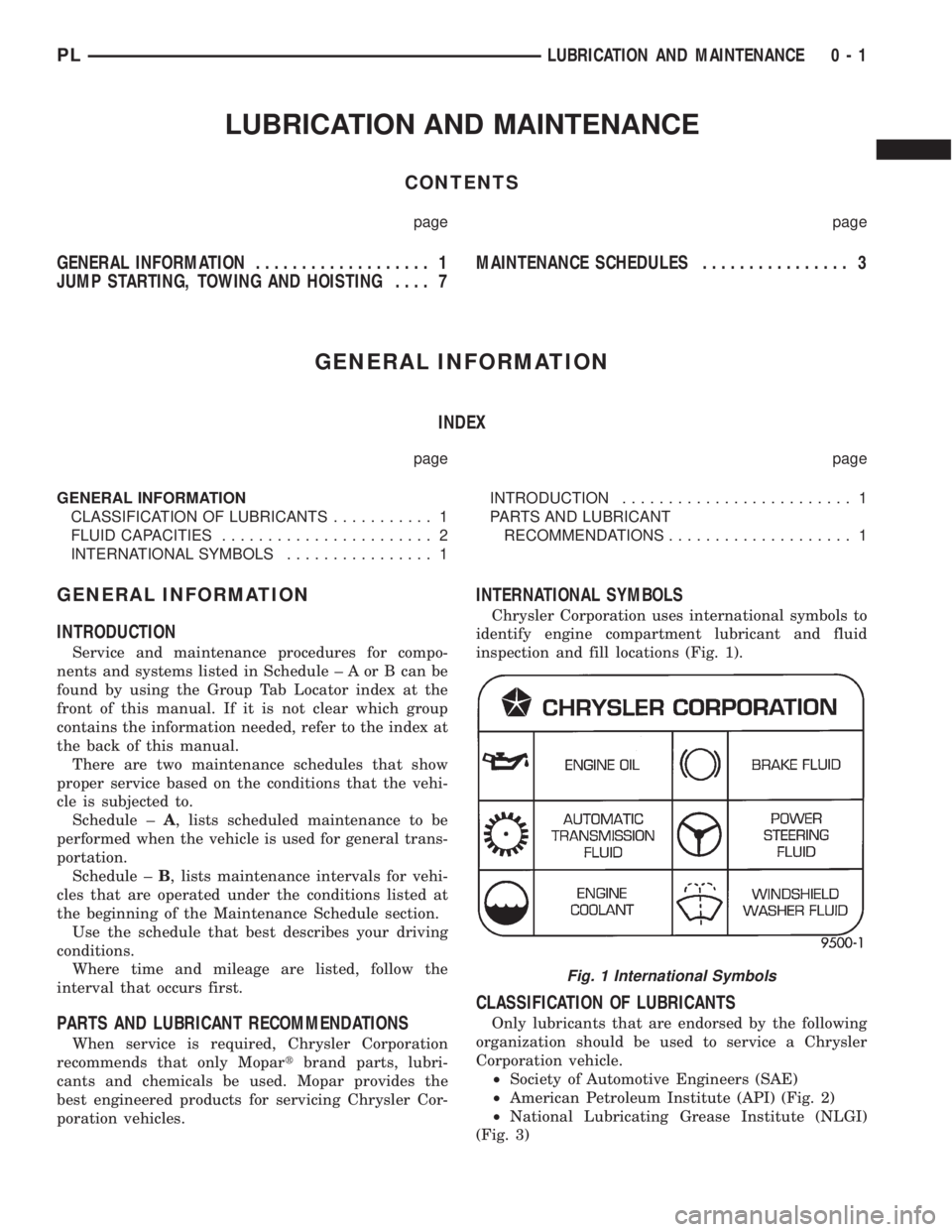
Chrysler Corporation uses international symbols to
identify engine compartment lubricant and fluid
inspection and fill locations (Fig. 1).
CLASSIFICATION OF LUBRICANTS
Only lubricants that are endorsed by the following
organization should be used to service a Chrysler
Corporation vehicle.
²Society of Automotive Engineers (SAE)
²American Petroleum Institute (API) (Fig. 2)
²National Lubricating Grease Institute (NLGI)
(Fig. 3)
Fig. 1 International Symbols
PLLUBRICATION AND MAINTENANCE 0 - 1
Page 4 of 1200
MAINTENANCE SCHEDULES
INDEX
page page
GENERAL INFORMATION
INTRODUCTION......................... 3
SCHEDULE ± A.......................... 3SCHEDULE ± B.......................... 4
UNSCHEDULED INSPECTION............... 3
GENERAL INFORMATION
INTRODUCTION
Service and maintenance procedures for compo-
nents and systems listed in Schedule ± A or B can be
found by using the Group Tab Locator index at the
front of this manual. If it is not clear which group
contains the information needed, refer to the index at
the back of this manual.
There are two maintenance schedules that show
proper service based on the conditions that the vehi-
cle is subjected to. Use the schedule that best
describes these conditions.
Schedule ±A, lists maintenance recommended for
vehicles used for general transportation.
Schedule ±B, lists maintenance recommended for
vehicles used under the following conditions:
²Frequent short trip driving less than 5 miles (8
km)
²Frequent driving in dusty conditions
²Frequent trailer towing
²Extensive idling
²More than 50% of your driving is at sustained
high speeds during hot weather, above 90ÉF (32ÉC)
Where time and mileage are listed, follow the
interval that occurs first.
EMISSION CONTROL SYSTEM MAINTENANCE
The scheduled emission maintenance listed inbold
typeon the Maintenance Schedules, must be done at
the mileage specified to assure the continued proper
functioning of the emission control system. These,
and all other maintenance services included in this
manual, should be done to provide the best vehicle
performance and reliability. More frequent mainte-
nance may be needed for vehicles in severe operating
conditions such as dusty areas and very short trip
driving.
UNSCHEDULED INSPECTION
At Each Stop For Fuel
²Check engine oil level, add as required.
²Check windshield washer solvent and add if
required.
Once A Month
²Check tire pressure and look for unusual wear
or damage.
²Inspect battery, clean, and tighten terminals as
required.
²Check fluid levels of coolant reservoir, power
steering and automatic transmission and add as
required.
²Check all lights and all other electrical items for
correct operation.
At Each Oil Change
²Inspect exhaust system.
²Inspect brake hoses.
²Inspect the CV joints and front suspension com-
ponents.
²Rotate the tires at each oil change interval
shown on Schedule ± A (7,500 miles) or every other
interval shown on schedule ± B (6,000 miles).
²Check coolant level, hoses and clamps.
²Check the manual transaxle fluid level.
²If the mileage is less than 7,500 miles (12 000
km) yearly, replace the engine oil filter at each oil
change.
SCHEDULE ± A
7,500 Miles (12 000 km) or at 6 months
²Change engine oil.
15,000 Miles (24 000 km) or at 12 months
²Change engine oil.
²Replace engine oil filter.
²Adjust drive belt tension.
22,500 Miles (36 000 km) or at 18 months
²Change engine oil.
²Inspect the front brake pads and rear brake lin-
ings.
30,000 Miles (48 000 km) or at 24 months
²Change engine oil.
²Replace engine oil filter.
²Lubricate front suspension ball joints.
²Adjust drive belt tension.
PLLUBRICATION AND MAINTENANCE 0 - 3
Page 209 of 1200
escapes to the atmosphere in the CRS tank and is
replaced with solid coolant on cool down.
TEMPERATURE GAUGE INDICATION
At idle the temperature gauge could rise slowly to
about 1/2 gauge travel. The fan will come on and the
gauge could drop to about 1/3 gauge travel, this is
normal.
SERVICE PROCEDURES
COOLANT LEVEL CHECKÐROUTINE
NOTE: Do not remove radiator cap for routine cool-
ant level inspections.
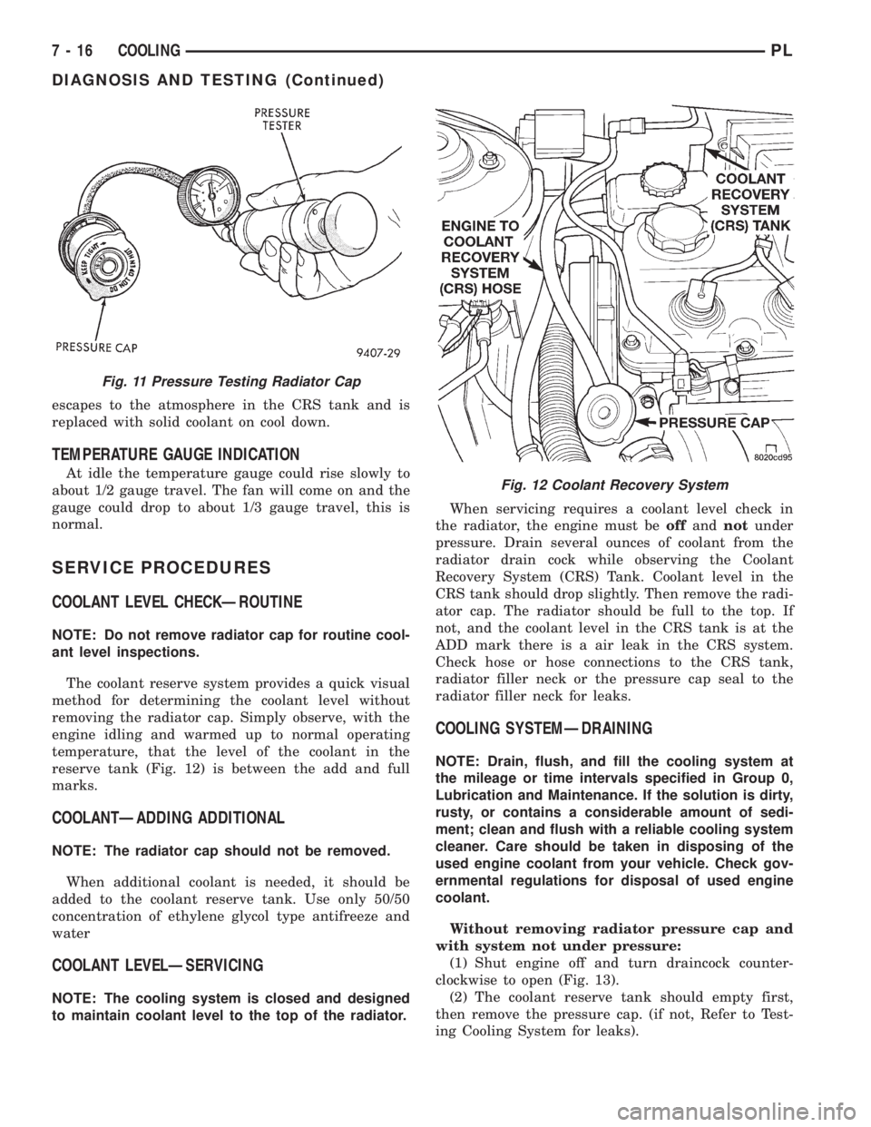
The coolant reserve system provides a quick visual
method for determining the coolant level without
removing the radiator cap. Simply observe, with the
engine idling and warmed up to normal operating
temperature, that the level of the coolant in the
reserve tank (Fig. 12) is between the add and full
marks.
COOLANTÐADDING ADDITIONAL
NOTE: The radiator cap should not be removed.
When additional coolant is needed, it should be
added to the coolant reserve tank. Use only 50/50
concentration of ethylene glycol type antifreeze and
water
COOLANT LEVELÐSERVICING
NOTE: The cooling system is closed and designed
to maintain coolant level to the top of the radiator.When servicing requires a coolant level check in
the radiator, the engine must beoffandnotunder
pressure. Drain several ounces of coolant from the
radiator drain cock while observing the Coolant
Recovery System (CRS) Tank. Coolant level in the
CRS tank should drop slightly. Then remove the radi-
ator cap. The radiator should be full to the top. If
not, and the coolant level in the CRS tank is at the
ADD mark there is a air leak in the CRS system.
Check hose or hose connections to the CRS tank,
radiator filler neck or the pressure cap seal to the
radiator filler neck for leaks.
COOLING SYSTEMÐDRAINING
NOTE: Drain, flush, and fill the cooling system at
the mileage or time intervals specified in Group 0,
Lubrication and Maintenance. If the solution is dirty,
rusty, or contains a considerable amount of sedi-
ment; clean and flush with a reliable cooling system
cleaner. Care should be taken in disposing of the
used engine coolant from your vehicle. Check gov-
ernmental regulations for disposal of used engine
coolant.
Without removing radiator pressure cap and
with system not under pressure:
(1) Shut engine off and turn draincock counter-
clockwise to open (Fig. 13).
(2) The coolant reserve tank should empty first,
then remove the pressure cap. (if not, Refer to Test-
ing Cooling System for leaks).
Fig. 11 Pressure Testing Radiator Cap
Fig. 12 Coolant Recovery System
7 - 16 COOLINGPL
DIAGNOSIS AND TESTING (Continued)
Page 251 of 1200
The major difference between the two engines is
component location which affects the ignition system
service procedures. There are various sensors that
are in different locations due to a different cylinder
head and intake manifold.
The 2.0L engines use a fixed ignition timing sys-
tem. The distributorless electronic ignition system is
referred to as the Direct Ignition System (DIS).
Basic ignition timing is not adjustable.The
Powertrain Control Module (PCM) determines spark
advance. The system's three main components are
the coil pack, crankshaft position sensor, and cam-
shaft position sensor.
POWERTRAIN CONTROL MODULE
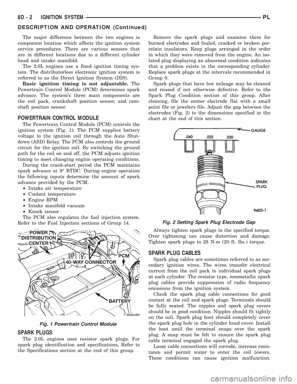
The Powertrain Control Module (PCM) controls the
ignition system (Fig. 1). The PCM supplies battery
voltage to the ignition coil through the Auto Shut-
down (ASD) Relay. The PCM also controls the ground
circuit for the ignition coil. By switching the ground
path for the coil on and off, the PCM adjusts ignition
timing to meet changing engine operating conditions.
During the crank-start period the PCM maintains
spark advance at 9É BTDC. During engine operation
the following inputs determine the amount of spark
advance provided by the PCM.
²Intake air temperature
²Coolant temperature
²Engine RPM
²Intake manifold vacuum
²Knock sensor
The PCM also regulates the fuel injection system.
Refer to the Fuel Injection sections of Group 14.
SPARK PLUGS
The 2.0L engines uses resistor spark plugs. For
spark plug identification and specifications, Refer to
the Specifications section at the end of this group.Remove the spark plugs and examine them for
burned electrodes and fouled, cracked or broken por-
celain insulators. Keep plugs arranged in the order
in which they were removed from the engine. An iso-
lated plug displaying an abnormal condition indicates
that a problem exists in the corresponding cylinder.
Replace spark plugs at the intervals recommended in
Group 0.
Spark plugs that have low mileage may be cleaned
and reused if not otherwise defective. Refer to the
Spark Plug Condition section of this group. After
cleaning, file the center electrode flat with a small
point file or jewelers file. Adjust the gap between the
electrodes (Fig. 2) to the dimensions specified in the
chart at the end of this section.
Always tighten spark plugs to the specified torque.
Over tightening can cause distortion and damage.
Tighten spark plugs to 28 N´m (20 ft. lbs.) torque.
SPARK PLUG CABLES
Spark plug cables are sometimes referred to as sec-
ondary ignition wires. The wires transfer electrical
current from the coil pack to individual spark plugs
at each cylinder. The resistor type, nonmetallic spark
plug cables provide suppression of radio frequency
emissions from the ignition system.
Check the spark plug cable connections for good
contact at the coil and spark plugs. Terminals should
be fully seated. The nipples and spark plug covers
should be in good condition. Nipples should fit tightly
on the coil. Spark plug boot should completely cover
the spark plug hole in the cylinder head cover. Install
the boot until the terminal snaps over the spark
plug. A snap must be felt to ensure the spark plug
cable terminal engaged the spark plug.
Loose cable connections will corrode, increase resis-
tance and permit water to enter the coil towers.
These conditions can cause ignition malfunction.
Fig. 1 Powertrain Control Module
Fig. 2 Setting Spark Plug Electrode Gap
8D - 2 IGNITION SYSTEMPL
DESCRIPTION AND OPERATION (Continued)
Page 390 of 1200
CHIME WARNING/REMINDER SYSTEM
CONTENTS
page page
GENERAL INFORMATION
INTRODUCTION......................... 1
DIAGNOSIS AND TESTING
CHIME SYSTEM CONDITIONS.............. 1
FASTEN SEAT BELTS..................... 1
HEADLAMPS LEFT ON.................... 1KEY LEFT IN IGNITION SWITCH............ 1
REMOVAL AND INSTALLATION
CHIME................................. 2
HEADLAMP SWITCH..................... 2
KEY-IN SWITCH......................... 2
SEAT BELT BUCKLE...................... 2
GENERAL INFORMATION
INTRODUCTION
WARNING: ON VEHICLES EQUIPPED WITH AN
AIRBAG, REFER TO THE AIRBAG PORTION OF
THIS SECTION FOR STEERING WHEEL OR SWITCH
REMOVAL AND INSTALLATION PROCEDURES.
The seat belt reminder system uses both visual
and audible signals. A combined seat belt and key
reminder chime with a red light on the instrument
panel.
The system will always illuminate the seat belt
reminder lamp for four to eight seconds when the
ignition switch is turned to the ON position. The
CHIME will sound during the same time interval if
the driver's seat belt is not fastened. Passenger belts
are not connected to the system. The chime will acti-
vate if the drivers door is opened and:
²The key is in the ignition switch, with the igni-
tion switch in either the OFF or accessory (ACC)
position
²The head lamps are ON.
The chime is part of the instrument cluster.
NOTE: This group covers both Left-Hand Drive
(LHD) and Right-Hand Drive (RHD) versions of this
model. Whenever required and feasible, the RHD
versions of affected vehicle components have been
constructed as mirror-image of the LHD versions.
While most of the illustrations used in this group
represent only the LHD version, the diagnostic and
service procedures outlined can generally be
applied to either version. Exceptions to this rule
have been clearly identified as LHD, RHD, or Export
if a special illustration or procedure is required.
DIAGNOSIS AND TESTING
FASTEN SEAT BELTS
To test the fasten seat belts function, turn the igni-
tion switch to the ON position with the driver's seat
belt unbuckled and fully retracted. The seat belt
warning lamp should light for four to eight seconds
and the tone should sound three to five times.
HEADLAMPS LEFT ON
To test the headlamps left on function:
²Turn headlamps
²Driver's door open
²Key removed from the ignition switch
Chime should sound until headlamps are turned
off or driver's door is closed.
KEY LEFT IN IGNITION SWITCH
To test the key left in ignition function, insert key
into the ignition and open driver's door. Chime
should sound until key is removed from ignition or
driver's door is closed.
CHIME SYSTEM CONDITIONS
The cluster harness connector, J1 is car right and
the J2 is car left.
NO TONE WHEN IGNITION SWITCH IS
TURNED ON AND DRIVERS SEAT BELT IS
UNBUCKLED
(1) Using an ohmmeter, with the seat belt fully
retracted, check for continuity to ground at Pin 4 of
the J1 wire harness connector (Fig. 1). If OK, go to
step 2. If not OK, repair as necessary .
(2) Check for continuity to ground at Pin 8 of the
J1 wire harness connector. If OK, go to Step 3. If not
OK, repair as necessary.
(3) Using voltmeter, check for battery feed at Pin 6
of the J1 wire harness connector. Check for ignition
feed at Pin 5 of the J1 wire harness connector. If not
OK, repair as necessary.
PLCHIME WARNING/REMINDER SYSTEM 8U - 1
Page 406 of 1200
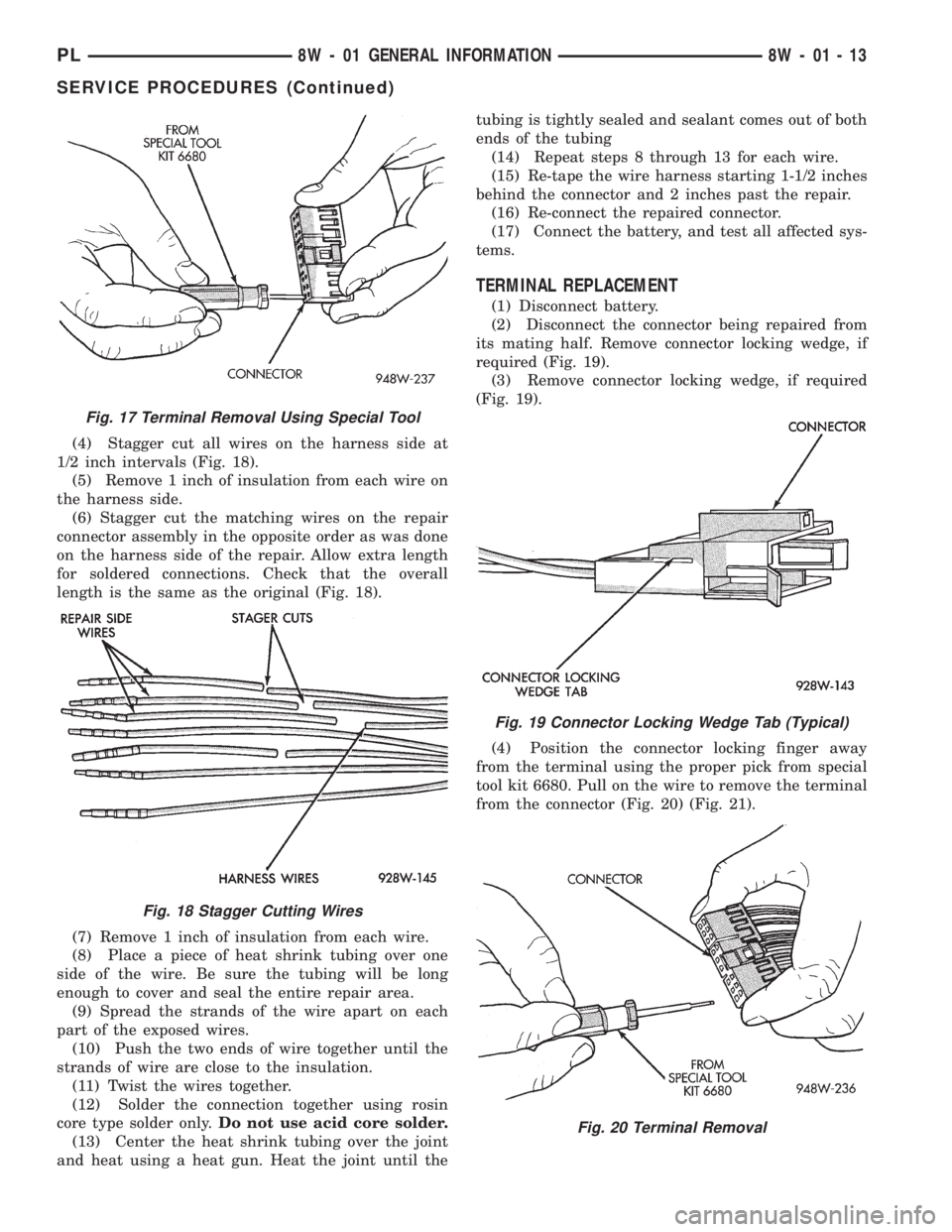
(4) Stagger cut all wires on the harness side at
1/2 inch intervals (Fig. 18).
(5) Remove 1 inch of insulation from each wire on
the harness side.
(6) Stagger cut the matching wires on the repair
connector assembly in the opposite order as was done
on the harness side of the repair. Allow extra length
for soldered connections. Check that the overall
length is the same as the original (Fig. 18).
(7) Remove 1 inch of insulation from each wire.
(8) Place a piece of heat shrink tubing over one
side of the wire. Be sure the tubing will be long
enough to cover and seal the entire repair area.
(9) Spread the strands of the wire apart on each
part of the exposed wires.
(10) Push the two ends of wire together until the
strands of wire are close to the insulation.
(11) Twist the wires together.
(12) Solder the connection together using rosin
core type solder only.Do not use acid core solder.
(13) Center the heat shrink tubing over the joint
and heat using a heat gun. Heat the joint until thetubing is tightly sealed and sealant comes out of both
ends of the tubing
(14) Repeat steps 8 through 13 for each wire.
(15) Re-tape the wire harness starting 1-1/2 inches
behind the connector and 2 inches past the repair.
(16) Re-connect the repaired connector.
(17) Connect the battery, and test all affected sys-
tems.
TERMINAL REPLACEMENT
(1) Disconnect battery.
(2) Disconnect the connector being repaired from
its mating half. Remove connector locking wedge, if
required (Fig. 19).
(3) Remove connector locking wedge, if required
(Fig. 19).
(4) Position the connector locking finger away
from the terminal using the proper pick from special
tool kit 6680. Pull on the wire to remove the terminal
from the connector (Fig. 20) (Fig. 21).
Fig. 17 Terminal Removal Using Special Tool
Fig. 18 Stagger Cutting Wires
Fig. 19 Connector Locking Wedge Tab (Typical)
Fig. 20 Terminal Removal
PL8W - 01 GENERAL INFORMATION 8W - 01 - 13
SERVICE PROCEDURES (Continued)
Page 718 of 1200
(2) Remove negative battery cable.
(3) Place a shop towel around the spark plugs
when removing them from the engine. This will catch
any fluid that may possibly be in the cylinder under
pressure.
(4) With all spark plugs removed, rotate engine
crankshaft using a breaker bar and socket.
(5) Identify the fluid in the cylinder(s) (i.e., cool-
ant, fuel, oil or other).
(6) Make sure all fluid has been removed from the
cylinders. Inspect engine for damage (i.e., Connecting
Rods, Pistons, Valves etc.)
(7) Repair engine or components as necessary to
prevent this problem from occurring again.
CAUTION: Squirt approximately 1 teaspoon of oil
into cylinders, rotate engine to lubricate the cylin-
der walls to prevent damage on restart.
(8) Install new spark plugs.
(9) Drain engine oil and remove oil filter.
(10) Fill engine with specified amount of approved
oil and install new oil filter.
(11) Connect negative battery cable.
(12) Start engine and check for any leaks.
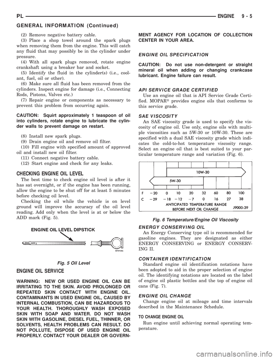
CHECKING ENGINE OIL LEVEL
The best time to check engine oil level is after it
has sat overnight, or if the engine has been running,
allow the engine to be shut off for at least 5 minutes
before checking oil level.
Checking the oil while the vehicle is on level
ground will improve the accuracy of the oil level
reading. Add only when the level is at or below the
ADD mark (Fig. 5).
ENGINE OIL SERVICE
WARNING: NEW OR USED ENGINE OIL CAN BE
IRRITATING TO THE SKIN. AVOID PROLONGED OR
REPEATED SKIN CONTACT WITH ENGINE OIL.
CONTAMINANTS IN USED ENGINE OIL, CAUSED BY
INTERNAL COMBUSTION, CAN BE HAZARDOUS TO
YOUR HEALTH. THOROUGHLY WASH EXPOSED
SKIN WITH SOAP AND WATER. DO NOT WASH
SKIN WITH GASOLINE, DIESEL FUEL, THINNER, OR
SOLVENTS, HEALTH PROBLEMS CAN RESULT. DO
NOT POLLUTE, DISPOSE OF USED ENGINE OIL
PROPERLY. CONTACT YOUR DEALER OR GOVERN-MENT AGENCY FOR LOCATION OF COLLECTION
CENTER IN YOUR AREA.
ENGINE OIL SPECIFICATION
CAUTION: Do not use non-detergent or straight
mineral oil when adding or changing crankcase
lubricant. Engine failure can result.
API SERVICE GRADE CERTIFIED
Use an engine oil that is API Service Grade Certi-
fied. MOPARtprovides engine oils that conforms to
this service grade.
SAE VISCOSITY
An SAE viscosity grade is used to specify the vis-
cosity of engine oil. Use only, engine oils with multi-
ple viscosities such as 5W-30 or 10W-30. These are
specified with a dual SAE viscosity grade which indi-
cates the cold-to-hot temperature viscosity range.
Select an engine oil that is best suited to your par-
ticular temperature range and variation (Fig. 6).
ENERGY CONSERVING OIL
An Energy Conserving type oil is recommended for
gasoline engines. They are designated as either
ENERGY CONSERVING or ENERGY CONSERV-
ING II.
CONTAINER IDENTIFICATION
Standard engine oil identification notations have
been adopted to aid in the proper selection of engine
oil. The identifying notations are located on the label
of engine oil plastic bottles and the top of engine oil
cans (Fig. 7).
ENGINE OIL CHANGE
Change engine oil at mileage and time intervals
described in the Maintenance Schedule.
TO CHANGE ENGINE OIL
Run engine until achieving normal operating tem-
perature.
Fig. 5 Oil Level
Fig. 6 Temperature/Engine Oil Viscosity
PLENGINE 9 - 5
GENERAL INFORMATION (Continued)