radio controls DODGE NEON 1999 Service Repair Manual
[x] Cancel search | Manufacturer: DODGE, Model Year: 1999, Model line: NEON, Model: DODGE NEON 1999Pages: 1200, PDF Size: 35.29 MB
Page 251 of 1200

The major difference between the two engines is
component location which affects the ignition system
service procedures. There are various sensors that
are in different locations due to a different cylinder
head and intake manifold.
The 2.0L engines use a fixed ignition timing sys-
tem. The distributorless electronic ignition system is
referred to as the Direct Ignition System (DIS).
Basic ignition timing is not adjustable.The
Powertrain Control Module (PCM) determines spark
advance. The system's three main components are
the coil pack, crankshaft position sensor, and cam-
shaft position sensor.
POWERTRAIN CONTROL MODULE
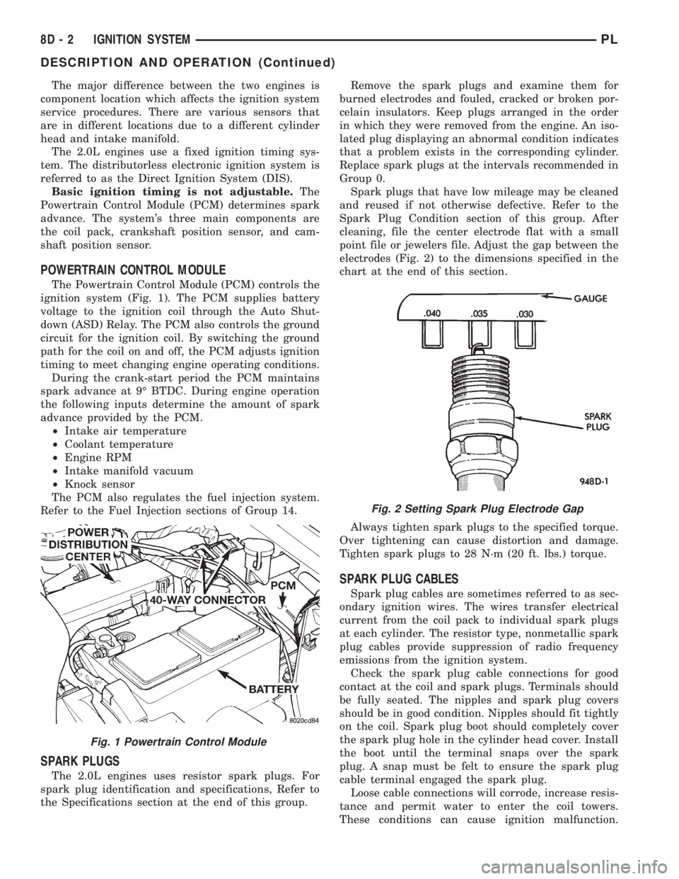
The Powertrain Control Module (PCM) controls the
ignition system (Fig. 1). The PCM supplies battery
voltage to the ignition coil through the Auto Shut-
down (ASD) Relay. The PCM also controls the ground
circuit for the ignition coil. By switching the ground
path for the coil on and off, the PCM adjusts ignition
timing to meet changing engine operating conditions.
During the crank-start period the PCM maintains
spark advance at 9É BTDC. During engine operation
the following inputs determine the amount of spark
advance provided by the PCM.
²Intake air temperature
²Coolant temperature
²Engine RPM
²Intake manifold vacuum
²Knock sensor
The PCM also regulates the fuel injection system.
Refer to the Fuel Injection sections of Group 14.
SPARK PLUGS
The 2.0L engines uses resistor spark plugs. For
spark plug identification and specifications, Refer to
the Specifications section at the end of this group.Remove the spark plugs and examine them for
burned electrodes and fouled, cracked or broken por-
celain insulators. Keep plugs arranged in the order
in which they were removed from the engine. An iso-
lated plug displaying an abnormal condition indicates
that a problem exists in the corresponding cylinder.
Replace spark plugs at the intervals recommended in
Group 0.
Spark plugs that have low mileage may be cleaned
and reused if not otherwise defective. Refer to the
Spark Plug Condition section of this group. After
cleaning, file the center electrode flat with a small
point file or jewelers file. Adjust the gap between the
electrodes (Fig. 2) to the dimensions specified in the
chart at the end of this section.
Always tighten spark plugs to the specified torque.
Over tightening can cause distortion and damage.
Tighten spark plugs to 28 N´m (20 ft. lbs.) torque.
SPARK PLUG CABLES
Spark plug cables are sometimes referred to as sec-
ondary ignition wires. The wires transfer electrical
current from the coil pack to individual spark plugs
at each cylinder. The resistor type, nonmetallic spark
plug cables provide suppression of radio frequency
emissions from the ignition system.
Check the spark plug cable connections for good
contact at the coil and spark plugs. Terminals should
be fully seated. The nipples and spark plug covers
should be in good condition. Nipples should fit tightly
on the coil. Spark plug boot should completely cover
the spark plug hole in the cylinder head cover. Install
the boot until the terminal snaps over the spark
plug. A snap must be felt to ensure the spark plug
cable terminal engaged the spark plug.
Loose cable connections will corrode, increase resis-
tance and permit water to enter the coil towers.
These conditions can cause ignition malfunction.
Fig. 1 Powertrain Control Module
Fig. 2 Setting Spark Plug Electrode Gap
8D - 2 IGNITION SYSTEMPL
DESCRIPTION AND OPERATION (Continued)
Page 376 of 1200

IMMOBILIZER SYSTEM
CONTENTS
page page
DESCRIPTION AND OPERATION
IMMOBILIZER RECEIVER................ 1
IMMOBILIZER SYSTEM.................. 1
IMMOBILIZER TRANSMITTER............. 2
POWER-UP MODE...................... 2
DIAGNOSIS AND TESTING
IMMOBILIZER DIAGNOSIS............... 2SERVICE PROCEDURES
VEHICLE IMMOBILIZER SYSTEM.......... 3
REMOVAL AND INSTALLATION
IMMOBILIZER RECEIVER................ 3
DESCRIPTION AND OPERATION
IMMOBILIZER SYSTEM
The Immobilizer system includes the following
unique items:
²An immobilizer module receiver that controls
system operation and also controls the RKE and Illu-
minated entry systems, if equipped.
²An encoded Crankshaft Position Sensor for the
ignition system. The Immobilizer module decodes the
signal from the crankshaft so the PCM can recognize
it as a valid Crankshaft Position Sensor signal, and
allow the engine to run.
²A wiring harness that interconnects the crank-
shaft sensor, the immobilizer receiver, and the PCM.
²Two key fob transmitters.
The Immobilizer System prevents unauthorized
operation of the vehicle by disabling the engine and
starter. The system will NOT allow the vehicle to
start unless the UNLOCK button on the RKE trans-
mitter is pressed. The system will be activated after
turning the ignition switch to the OFF position and
using one of the following methods.
(1) Press the LOCK button on the RKE transmit-
ter.
(2) LOCK the doors by pressing a power lock but-
ton switch.
(3) LOCK the driver or passenger door using the
key.
²The Security light will flash, for about 16 sec-
onds, indicating that the engine and starter will be
disabled.
²The Security light remaining on, indicates the
system is not operational.
²The Immobilizer will activate automatically
within 10 minutes of the ignition switch being in the
OFF position, whether the vehicle has been locked or
unlocked.²An attempt to start the vehicle without pressing
the UNLOCK button on the RKE transmitter will
result in a warning chime and the Security light
flashing.
NOTE: The ignition switch must be in the OFF posi-
tion in order for the system to be activated, whether
the doors are closed or not.
IMMOBILIZER RECEIVER
The immobilizer receiver is programmed to
respond to the Lock and Unlock radio signals issued
by the immobilizer transmitters. The receiver will
only respond to the radio signals of transmitters (up
to four) whose vehicle access codes have been stored
in the receiver's electronic memory. The receiver is
programmed at the assembly plant with the vehicle
access codes of the two transmitters that are shipped
with the vehicle.
The immobilizer receiver also has a central pro-
cessing unit, which contains the immobilizer system
logic. The programming in the immobilizer receiver
allows the system to learn and retain transmitter
vehicle access codes, as well as to communicate with
the Powertrain Control Module (PCM) and/or the
DRB scan tool on the Chrysler Collision Detection
(CCD) data bus network.
The CCD data bus network allows the sharing of
sensor information. This helps to reduce wiring har-
ness complexity, reduce internal controller hardware,
and reduce component sensor current loads. At the
same time, the CCD data bus network provides
increased reliability and enhanced diagnostic capabil-
ities.
Each immobilizer transmitter has a different vehi-
cle access code, which must be programmed into the
memory of the immobilizer receiver in the vehicle in
order to operate the immobilizer system. A DRB scan
tool must be used to program new or additional
PLIMMOBILIZER SYSTEM 8Q - 1