ground clearance DODGE NEON 1999 Service Repair Manual
[x] Cancel search | Manufacturer: DODGE, Model Year: 1999, Model line: NEON, Model: DODGE NEON 1999Pages: 1200, PDF Size: 35.29 MB
Page 9 of 1200
DISCONNECT CABLE CLAMPS AS FOLLOWS:
²Disconnect BLACK cable clamp from engine
ground on disabled vehicle.
²When using a Booster vehicle, disconnect
BLACK cable clamp from battery negative terminal.
Disconnect RED cable clamp from battery positive
terminal.
²Disconnect RED cable clamp from battery posi-
tive terminal on disabled vehicle.
TOWING RECOMMENDATIONS
WARNING: DO NOT ALLOW TOWING ATTACH-
MENT DEVICES TO CONTACT THE FUEL TANK OR
LINES, FUEL LEAK CAN RESULT. DO NOT LIFT OR
TOW VEHICLE BY FRONT OR REAR BUMPER, OR
BUMPER ENERGY ABSORBER UNITS. DO NOT
VENTURE UNDER A LIFTED VEHICLE IF NOT SUP-
PORTED PROPERLY ON SAFETY STANDS. DO NOT
ALLOW PASSENGERS TO RIDE IN A TOWED VEHI-
CLE. USE A SAFETY CHAIN THAT IS INDEPENDENT
FROM THE TOWING ATTACHMENT DEVICE.
CAUTION: Do not damage brake lines, exhaust
system, shock absorbers, sway bars, or any other
under vehicle components when attaching towing
device to vehicle. Do not attach towing device to
front or rear suspension components. Do not
secure vehicle to towing device by the use of front
or rear suspension or steering components.
Remove or secure loose or protruding objects from
a damaged vehicle before towing. Refer to state and
local rules and regulations before towing a vehicle.
Do not allow weight of towed vehicle to bear on
lower fascia, air dams, or spoilers.
RECOMMENDED TOWING EQUIPMENT
To avoid damage to bumper fascia and air dams
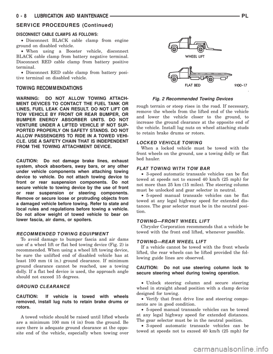
use of a wheel lift or flat bed towing device (Fig. 2) is
recommended. When using a wheel lift towing device,
be sure the unlifted end of disabled vehicle has at
least 100 mm (4 in.) ground clearance. If minimum
ground clearance cannot be reached, use a towing
dolly. If a flat bed device is used, the approach angle
should not exceed 15 degrees.
GROUND CLEARANCE
CAUTION: If vehicle is towed with wheels
removed, install lug nuts to retain brake drums or
rotors.
A towed vehicle should be raised until lifted wheels
are a minimum 100 mm (4 in) from the ground. Be
sure there is adequate ground clearance at the oppo-
site end of the vehicle, especially when towing overrough terrain or steep rises in the road. If necessary,
remove the wheels from the lifted end of the vehicle
and lower the vehicle closer to the ground, to
increase the ground clearance at the opposite end of
the vehicle. Install lug nuts on wheel attaching studs
to retain brake drums or rotors.
LOCKED VEHICLE TOWING
When a locked vehicle must be towed with the
front wheels on the ground, use a towing dolly or flat
bed hauler.
FLAT TOWING WITH TOW BAR
²3-speed automatic transaxle vehicles can be flat
towed at speeds not to exceed 40 km/h (25 mph) for
not more than 25 km (15 miles). The steering column
must be unlocked and gear selector in neutral.
²5-speed manual transaxle vehicles can be flat
towed at any legal highway speed for extended dis-
tances. The gear selector must be in the neutral posi-
tion.
TOWINGÐFRONT WHEEL LIFT
Chrysler Corporation recommends that a vehicle be
towed with the front end lifted, whenever possible.
TOWINGÐREAR WHEEL LIFT
If a vehicle cannot be towed with the front wheels
lifted, the rear wheels can be lifted provided the fol-
lowing guide lines are observed.
CAUTION: Do not use steering column lock to
secure steering wheel during towing operation.
²Unlock steering column and secure steering
wheel in straight ahead position with a clamp device
designed for towing.
²Verify that front drive line and steering compo-
nents are in good condition.
²5-speed manual transaxle vehicles can be towed
at any legal highway speed for extended distances.
The gear selector must be in the neutral position.
²3-speed automatic transaxle vehicles can be
towed at speeds not to exceed 40 km/h (25 mph) for
Fig. 2 Recommended Towing Devices
0 - 8 LUBRICATION AND MAINTENANCEPL
SERVICE PROCEDURES (Continued)
Page 148 of 1200
(3) Remove the rubber plug from the adjusting
hole in the brake shoe backing plate on both sides of
the vehicle.
(4)Driver (left) side park brake shoe adjust-
ment procedure.Insert a medium size screwdriver
through adjustment hole in backing plate. Position
the srewdriver against the starwheel on the park
brake shoe adjuster mechanism. Using the screw-
driver rotate the starwheeldownwarduntil a slight
drag is felt when turning the rear tire and wheel.
Then, using the screwdriver rotate the starwheel
upwardjust until the rear tire and wheel can be
rotated with no park brake shoe drag. From the
point where there is no more park brake drag rotate
the starwheelupwarda maximum of two additional
clicks. The park brake shoe to drum clearance is
know properly adjusted.
(5)Passenger (right) side park brake shoe
adjustment procedure.Insert a medium size
screwdriver through adjustment hole in backing
plate. Position the srewdriver against the starwheel
on the park brake shoe adjuster mechanism. Using
the screwdriver rotate the starwheelupwarduntil a
slight drag is felt when turning the rear tire and
wheel. Then, using the screwdriver rotate the star-
wheeldownwardjust until the rear tire and wheel
can be rotated with no park brake shoe drag. From
the point where there is no more park brake drag
rotate the starwheeldownwarda maximum of two
additional clicks. The park brake shoe to drum clear-
ance is know properly adjusted.
(6) Install the rubber plug in the adjusting hole on
the brake shoe backing plate on both sides of the
vehicle.
(7) Lower vehicle far enough to allow access the
park brake lever. The rear tires must not be on the
ground.
(8) Fully apply and release the park brakes two
times after adjusting the park brake shoes. Then
rotate both rear wheels to ensure that the park
brake shoes do not drag on the brake drum following
the application and release of the park brakes.
SPECIFICATIONS
BRAKE FLUID
The brake fluid used in this vehicle must conform
to DOT 3 specifications and SAE J1703 standards.
No other type of brake fluid is recommended or
approved for usage in the vehicle brake system. Use
only Mopar brake fluid or an equivalent from a
tightly sealed container.
CAUTION: Never use reclaimed brake fluid or fluid
from an container which has been left open. Anopen container will absorb moisture from the air
and contaminate the fluid.
CAUTION: Never use any type of a petroleum-
based fluid in the brake hydraulic system. Use of
such type fluids will result in seal damage of the
vehicle brake hydraulic system causing a failure of
the vehicle brake system. Petroleum based fluids
would be items such as engine oil, transmission
fluid, power steering fluid ect.
BRAKE ACTUATION SYSTEM
ACTUATION:
Vacuum Operated Power Brakes.........Standard
Hydraulic System...........Dual-Diagonally Split
MASTER CYLINDER ASSEMBLY:
Type ...........................Dual Tandem
Body Material...............Anodized Aluminum
Reservoir Material................Polypropelene
MASTER CYLINDER BORE / STROKE
AND SPLIT:
NonABS ....21mmx32.6 mm (.875 in. x 1.28 in.)
ABS........21mmx32.7 mm (.874 in. x 1.29 in.)
Displacement Split.....................50/50
MASTER CYLINDER FLUID OUTLET PORTS:
ABS ..........Primary 3/8±24 Secondary 7/16±24
Non ABS . . .Primary Inboard And Outboard 7/16±24
Non ABS . . .Secondary Inboard And Outboard 3/8±23
Outlet Fitting Type.......SAE 45 É Inverted Flare
ABS HYDRAULIC CONTROL UNIT:
Hydraulic Tube Fitting Type.SAE 45 É Inverted Flare
BOOSTER:
Make/Type.........Bendix Vacuum W/&W/O ABS
Mounting Studs.....................M8x1.25
Type ..........................230 mm Single
Boost At 20 inches Of Manifold Vacuum. . . .4690 All
PROPORTIONING VALVE:
Material...........................Aluminum
Function........Hydraulic Pressure Proportioning
BRAKE PEDAL
Pedal Ratio.............................3.28
BRAKE FASTENER TORQUE SPECIFICATIONS
DESCRIPTION TORQUE
BRAKE TUBES:
Tube Nuts To Fittings And
Components Except HCU. . . . 17 N´m (145 in. lbs.)
From Master Cylinder To
HCU At HCU Ports........21N´m(185 in. lbs.)
BRAKE HOSE:
To Caliper Banjo Bolt..........48N´m(35ft.lbs.)
Intermediate Bracket.........12N´m(105 in. lbs.)
PLBRAKES 5 - 67
ADJUSTMENTS (Continued)
Page 160 of 1200
A visual inspection for loose, disconnected, or mis-
routed wires should be done before attempting to
diagnose or service the ITT Teves Mark 20 antilock
brake system. A visual inspection will eliminate
unnecessary testing and diagnostics time. A thorough
visual inspection will include the following compo-
nents and areas of the vehicle.
(1) Inspect fuses in the power distribution center
(PDC) and the wiring junction block. Verify that all
fuses are fully inserted into the PDC and wring junc-
tion block. A label on the underside of the PDC cover
identifies the locations of the ABS fuses in the PDC.
(2) Inspect the 25-way electrical connector at the
CAB for damage, spread or backed-out wiring termi-
nals. Verify that the 25-way connector is fully
inserted in the socket on the CAB. Be sure that wires
are not stretched tight or pulled out of the connector.
(3) Verify that all the wheel speed sensor connec-
tions are secure.
(4) Poor mating of connector halves or terminals
not fully seated in the connector body.
(5) Improperly formed or damaged terminals. All
connector terminals in a suspect circuit should be
carefully reformed to increase contact tension.
(6) Poor terminal to wire connection. This requires
removing the terminal from the connector body to
inspect.
(7) Pin presence in the connector assembly
(8) Proper ground connections. Check all ground
connections for signs of corrosion, tight fasteners, or
other potential defects. Refer to wiring diagram man-
ual for ground locations.
(9) Problems with main power sources of the vehi-
cle. Inspect battery, generator, ignition circuits and
other related relays and fuses.
(10) If a visual check does not find the cause of the
problem, operate the car in an attempt to duplicate
the condition and record the trouble code.
(11) Most failures of the ABS system will disable
ABS function for the entire ignition cycle even if the
fault clears before key-off. There are some failure
conditions, however, which will allow ABS operation
to resume during the ignition cycle in which a failure
occurred if the failure conditions are no longer
present. The following conditions may result in inter-
mittent illumination of the ABS Warning Lamp. All
other failures will cause the lamp to remain on until
the ignition switch is turned off. Circuits involving
these inputs to the CAB should be investigated if a
complaint of intermittent warning system operation
is encountered.
(12) Low system voltage. If Low System Voltage is
detected by the CAB, the CAB will turn on the ABS
Warning Lamp until normal system voltage is
achieved. Once normal voltage is seen at the CAB,
normal operation resumes.(13) High system voltage. If high system voltage is
detected by the CAB, the CAB will turn on the
Amber ABS Warning Lamp until normal system volt-
age is achieved. Once normal voltage is again
detected by the CAB, normal ABS operation resumes.
(14) Additionally, any condition which results in
interruption of electrical current to the CAB or mod-
ulator assembly may cause the ABS Warning Lamp
to turn on intermittently.
(15) The body controller can turn on the (yellow)
ABS warning lamp if CCD communication between
the body controller and the CAB is interupted.
TONEWHEEL INSPECTION
CAUTION: The tone wheels used on this vehicle
equipped with the Teves Mark 20 Antilock Brake
System are different then those used on past mod-
els of this vehicle equipped with antilock brakes.
Reduced braking performance will result if this part
is used on earlier model vehicles and an accident
could result. Do not use on pre-1998 model year
vehicles.
Carefully inspect tonewheel at the suspected faulty
wheel speed sensor for missing, chipped or broken
teeth, this can cause erratic speed sensor signals.
Tonewheels should show no evidence of contact
with the wheel speed sensors. If contact was made,
determine cause and correct before replacing the
wheel speed sensor.
Excessive runout of the tonewheel can cause
erratic wheel speed sensor signals. Refer to Tone-
wheel Runout in the Specification Section in this sec-
tion of the service manual for the tonewheel runout
specification. Replace drive shaft assembly or rear
hub/bearing assembly if tonewheel runout exceeds
the specification.
Inspect tonewheels for looseness on their mounting
surfaces. Tonewheels are pressed onto their mounting
surfaces and should not rotate independently from
the mounting surface.
Check the wheel speed sensor head alignment to
the tone wheel. Also check the gap between the speed
sensor head and the tone wheel to ensure it is at
specification. Refer to Wheel Speed Sensor Clearance
in the Specification Section in this section of the ser-
vice manual.
PROPORTIONING VALVE
CAUTION: Proportioning valves should never be
disassembled.
If premature rear wheel skid occurs on a hard
brake application, it could be an indication that a
PLBRAKES 5 - 79
DIAGNOSIS AND TESTING (Continued)
Page 212 of 1200
RADIATOR
REMOVAL
WARNING: DO NOT REMOVE THE CYLINDER
BLOCK PLUG OR THE RADIATOR DRAINCOCK
WITH THE SYSTEM HOT AND UNDER PRESSURE
BECAUSE SERIOUS BURNS FROM COOLANT CAN
OCCUR.
(1) Disconnect negative battery cable from battery.
(2) Drain cooling system. Refer to Cooling System
Draining in this section.
(3) Remove engine air inlet duct.
(4) Remove upper radiator hose from the radiator.
(5) Disconnect and cap automatic transmission
hoses, if equipped.
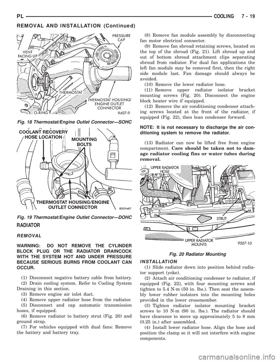
(6) Remove radiator to battery strut (Fig. 20) and
ground strap.
(7) For vehicles equipped with dual fans: Remove
the battery and battery tray.(8) Remove fan module assembly by disconnecting
fan motor electrical connector.
(9) Remove fan shroud retaining screws, located on
the top of the shroud (Fig. 21). Lift shroud up and
out of bottom shroud attachment clips separating
shroud from radiator. For dual fan applications the
left fan module may be removed first, then the right
side module last. Fan damage should always be
avoided.
(10) Remove the lower radiator hose.
(11) Remove upper radiator isolator bracket
mounting screws (Fig. 20). Disconnect the engine
block heater wire if equipped.
(12) Remove the air conditioning condenser attach-
ing screws located at the front of the radiator, if
equipped (Fig. 22), then lean condenser forward.
NOTE: It is not necessary to discharge the air con-
ditioning system to remove the radiator.
(13) Radiator can now be lifted free from engine
compartment.Care should be taken not to dam-
age radiator cooling fins or water tubes during
removal.
INSTALLATION
(1) Slide radiator down into position behind radia-
tor support (yoke).
(2) Attach air conditioning condenser to radiator, if
equipped (Fig. 22), with four mounting screws and
tighten to 5.4 N´m (50 in. lbs.). Then seat the assem-
bly lower rubber isolators into the mounting holes
provided in the lower crossmember.
(3) Tighten radiator isolator mounting bracket
screws to 10 N´m (90 in. lbs.). The radiator should
have clearance to move up approximately 5 to 8 mm
(0.25 in.) after assembled.
(4) Install lower radiator hose. Align the hose and
position the clamp so it will not interfere with engine
components.
Fig. 18 Thermostat/Engine Outlet ConnectorÐSOHC
Fig. 19 Thermostat/Engine Outlet ConnectorÐDOHC
Fig. 20 Radiator Mounting
PLCOOLING 7 - 19
REMOVAL AND INSTALLATION (Continued)
Page 1007 of 1200
VEHICLE SPEED SENSOR PINION GEAR
When the sensor is removed for any reason, a
NEW O-ring must be installed on its outside diame-
ter.
REMOVAL
(1) Remove harness connector from sensor. Be sure
weather seal stays on harness connector.
(2) Remove bolt securing the sensor in the exten-
sion housing.
(3) Carefully pull sensor and pinion gear assembly
out of extension housing.
(4) Remove pinion gear from sensor.
INSTALLATION
(1) To install, reverse the above procedure. Be sure
extension housing and sensor flange are clean prior
to installation. Always use a NEW sensor O-ring.
(2) Tighten bolt to 7 N´m (60 in. lbs.). Tighten
speedometer cable to 4 N´m (35 in. lbs.).
PARK/NEUTRAL STARTING AND BACK-UP LAMP
SWITCH
TEST
The park/neutral starting switch is the center ter-
minal of the three terminal switch. It provides
ground for the starter solenoid circuit through the
selector lever in PARK and NEUTRAL positions only.
(1) To test switch, remove wiring connector from
switch and test for continuity between center pin of
switch and transaxle case. Continuity should exist
only when transaxle is in PARK or NEUTRAL.
(2) Check gearshift cable adjustment before replac-
ing a switch that tests bad.
REMOVAL
(1) Unscrew switch from transaxle case allowing
fluid to drain into a container. Move selector lever to
PARK, then to NEUTRAL position, and inspect to see
the switch operating lever fingers are centered in
switch opening.
INSTALLATION
(1) Screw the switch with a new seal into tran-
saxle case and tighten to 33 N´m (24 ft. lbs.). Retest
switch with the test lamp.
(2) Add fluid to transaxle to bring up to proper
level.
(3) The back-up lamp switch circuit is through the
two outside terminals of the three terminal switch.
(4) To test switch, remove wiring connector from
switch and test for continuity between the two out-
side pins.
(5) Continuity should exist only with transaxle in
REVERSE position.(6) No continuity should exist from either pin to
the case.
TRANSAXLE
REMOVAL
NOTE: The transaxle can be removed from the
vehicle without having to remove the engine.
The transaxle and torque converter must be
removed as an assembly; otherwise, the torque con-
verter drive plate, pump bushing, or oil seal may be
damaged. The drive plate will not support a load;
therefore, none of the weight of the transaxle should
be allowed to rest on the plate during removal.
All transaxle components are serviced with the
transaxle out of the vehicle. The components that are
serviceable in the vehicle are:
²Axle shaft seals
²Back±up lamp switch
²End plate
²Extension housing
²Neutral safety switch
²Shift lever
²Transaxle oil pan
²Valve Body
²Vehicle speed sensor
(1) Disconnect the battery.
(2) Pull Power Distribution Center up and out of
its holding bracket. Set Power Distribution Center
aside to gain clearance.
(3) Remove battery heat shield and remove battery
from engine compartment. Remove battery tray from
engine compartment. Disconnect cruise control (if
equipped).
(4) Remove vehicle speed sensor wiring.
(5) Disconnect neutral safety switch and torque
converter control wiring at transaxle.
CAUTION: Pry up with equal force on both sides of
shifter cable isolator bushing to avoid damaging
cable isolator bushing.
(6) Disconnect gear shift cable end from transaxle
shift lever (Fig. 22). Remove bracket bolt at transaxle
(Fig. 23).
(7) Remove throttle pressure control cable from
lever. Then remove bracket bolts at the transaxle
(Fig. 24).
(8) Remove dipstick tube.
(9) Remove transaxle cooler lines and plug lines
(Fig. 25).
(10) Remove throttle pressure control cable sup-
port bracket bolts. Remove upper bellhousing bolts
and upper starter bolt (Fig. 26).
21 - 64 TRANSAXLEPL
REMOVAL AND INSTALLATION (Continued)