cruise control DODGE NEON 1999 Service Repair Manual
[x] Cancel search | Manufacturer: DODGE, Model Year: 1999, Model line: NEON, Model: DODGE NEON 1999Pages: 1200, PDF Size: 35.29 MB
Page 303 of 1200
OVERSHOOT/UNDERSHOOT FOLLOWING SPEED
CONTROL SET
If the operator repeatedly presses and releases the
set button with their foot off of the accelerator (a ªlift
foot setº to begin speed control operation), the vehicle
may accelerate and exceed the desired set speed by
up to 5 MPH (8 km/h) and then decelerate to less
than the desired set speed before finally achieving
the desired set speed.
The Speed Control has an adaptive strategy that
compensates for vehicle-to-vehicle variations in speed
control cable lengths. When the speed control is set
with the vehicle operators foot off of the accelerator
pedal, the speed control thinks there is excessive
speed control cable slack and adapts. If the lift foot
sets are continually used, the speed control over-
shoot/undershoot condition will develop.
To ªunlearnº the overshoot/undershoot condition,
the vehicle operator has to press and release the set
button while maintaining the desired set speed with
the accelerator pedal (not decelerating or accelerat-
ing), and then turn the cruise control switch to the
OFF position (or press the CANCEL button if
equipped) after waiting 10 seconds. This procedure
must be performed approximately 10±15 times to
completely unlearn the overshoot/undershoot condi-
tion.
SERVO VACUUM TEST
(1) Turn ignition switch to the ON position with-
out starting engine. Activate speed control ON
switch.
(2) Disconnect the four-way electrical connector
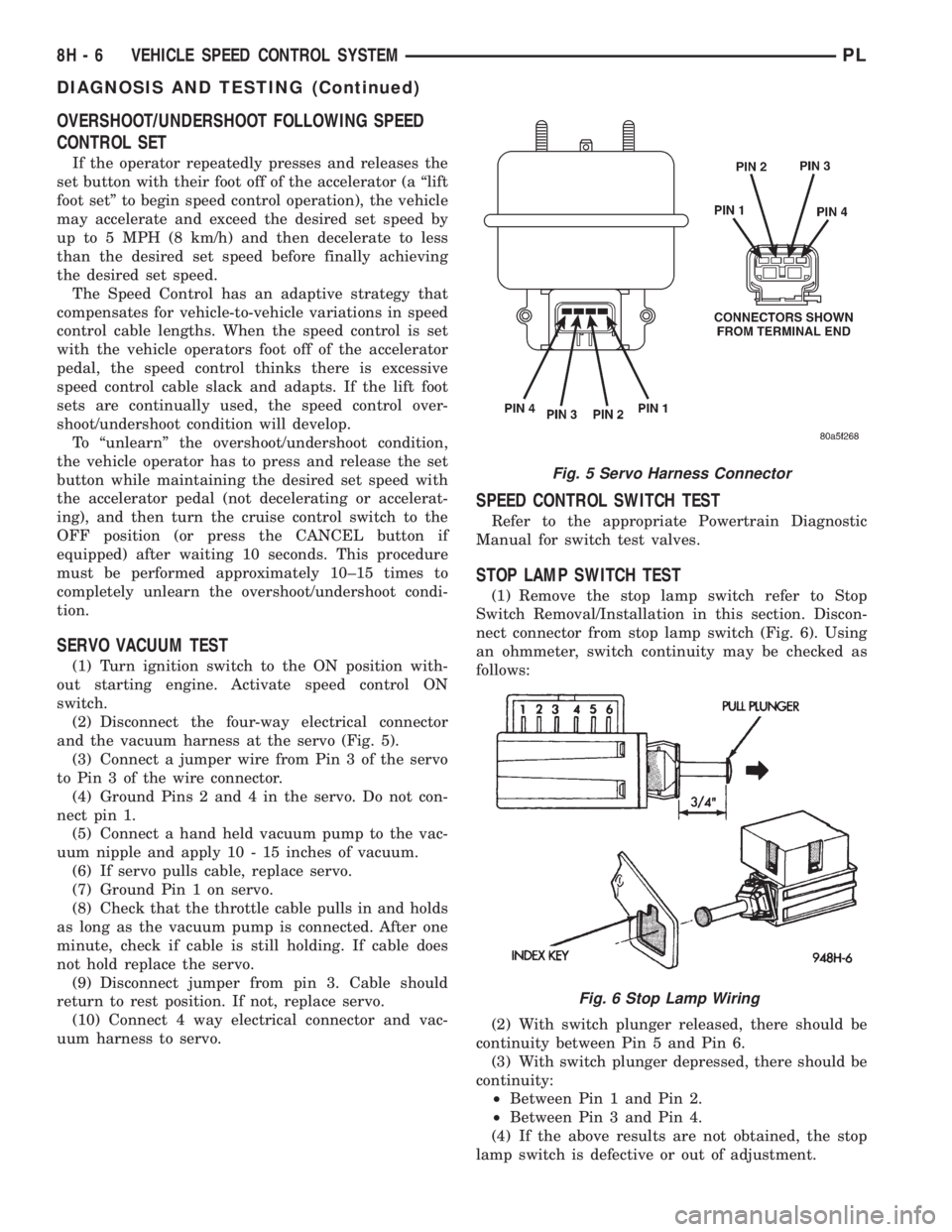
and the vacuum harness at the servo (Fig. 5).
(3) Connect a jumper wire from Pin 3 of the servo
to Pin 3 of the wire connector.
(4) Ground Pins 2 and 4 in the servo. Do not con-
nect pin 1.
(5) Connect a hand held vacuum pump to the vac-
uum nipple and apply 10 - 15 inches of vacuum.
(6) If servo pulls cable, replace servo.
(7) Ground Pin 1 on servo.
(8) Check that the throttle cable pulls in and holds
as long as the vacuum pump is connected. After one
minute, check if cable is still holding. If cable does
not hold replace the servo.
(9) Disconnect jumper from pin 3. Cable should
return to rest position. If not, replace servo.
(10) Connect 4 way electrical connector and vac-
uum harness to servo.
SPEED CONTROL SWITCH TEST
Refer to the appropriate Powertrain Diagnostic
Manual for switch test valves.
STOP LAMP SWITCH TEST
(1) Remove the stop lamp switch refer to Stop
Switch Removal/Installation in this section. Discon-
nect connector from stop lamp switch (Fig. 6). Using
an ohmmeter, switch continuity may be checked as
follows:
(2) With switch plunger released, there should be
continuity between Pin 5 and Pin 6.
(3) With switch plunger depressed, there should be
continuity:
²Between Pin 1 and Pin 2.
²Between Pin 3 and Pin 4.
(4) If the above results are not obtained, the stop
lamp switch is defective or out of adjustment.
Fig. 5 Servo Harness Connector
Fig. 6 Stop Lamp Wiring
8H - 6 VEHICLE SPEED CONTROL SYSTEMPL
DIAGNOSIS AND TESTING (Continued)
Page 862 of 1200
GENERAL INFORMATION
INTRODUCTION
All engines used in this section have a sequential
Multi-Port Electronic Fuel Injection system. The MPI
system is computer regulated and provides precise
air/fuel ratios for all driving conditions. The Power-
train Control Module (PCM) operates the fuel injec-
tion system.
The PCM regulates:
²Ignition timing
²Air/fuel ratio
²Emission control devices
²Cooling fan
²Charging system
²Idle speed
²Vehicle speed control
Various sensors provide the inputs necessary for
the PCM to correctly operate these systems. In addi-
tion to the sensors, various switches also provide
inputs to the PCM.
All inputs to the PCM are converted into signals.
The PCM can adapt its programming to meet chang-
ing operating conditions.
Fuel is injected into the intake port above the
intake valve in precise metered amounts through
electrically operated injectors. The PCM fires the
injectors in a specific sequence. Under most operat-
ing conditions, the PCM maintains an air fuel ratio
of 14.7 parts air to 1 part fuel by constantly adjust-
ing injector pulse width. Injector pulse width is the
length of time the injector is open.
The PCM adjusts injector pulse width by opening
and closing the ground path to the injector. Engine
RPM (speed) and manifold absolute pressure (air
density) are the primary inputs that determine injec-
tor pulse width.
MODES OF OPERATION
As input signals to the PCM change, the PCM
adjusts its response to output devices. For example,
the PCM must calculate a different injector pulse
width and ignition timing for idle than it does for
Wide Open Throttle (WOT). There are several differ-
ent modes of operation that determine how the PCM
responds to the various input signals.
There are two different areas of operation, OPEN
LOOP and CLOSED LOOP.
During OPEN LOOP modes the PCM receives
input signals and responds according to preset PCM
programming. Inputs from the upstream and down-
stream heated oxygen sensors are not monitored dur-
ing OPEN LOOP modes, except for heated oxygen
sensor diagnostics (they are checked for shorted con-
ditions at all times).During CLOSED LOOP modes the PCM monitors
the inputs from the upstream and downstream
heated oxygen sensors. The upstream heated oxygen
sensor input tells the PCM if the calculated injector
pulse width resulted in the ideal air-fuel ratio of 14.7
to one. By monitoring the exhaust oxygen content
through the upstream heated oxygen sensor, the
PCM can fine tune injector pulse width. Fine tuning
injector pulse width allows the PCM to achieve opti-
mum fuel economy combined with low emissions.
For the PCM to enter CLOSED LOOP operation,
the following must occur:
(1) Engine coolant temperature must be over 35ÉF.
²If the coolant is over 35É the PCM will wait 44
seconds.
²If the coolant is over 50ÉF the PCM will wait 38
seconds.
²If the coolant is over 167ÉF the PCM will wait
11 seconds.
(2) For other temperatures the PCM will interpo-
late the correct waiting time.
(3) O2 sensor must read either greater than .745
volts or less than .1 volt.
(4) The multi-port fuel injection systems has the
following modes of operation:
²Ignition switch ON (Zero RPM)
²Engine start-up
²Engine warm-up
²Cruise
²Idle
²Acceleration
²Deceleration
²Wide Open Throttle
²Ignition switch OFF
(5) The engine start-up (crank), engine warm-up,
deceleration with fuel shutoff and wide open throttle
modes are OPEN LOOP modes. Under most operat-
ing conditions, the acceleration, deceleration (with
A/C on), idle and cruise modes,with the engine at
operating temperatureare CLOSED LOOP modes.
IGNITION SWITCH ON (ZERO RPM) MODE
When the ignition switch activates the fuel injec-
tion system, the following actions occur:
²The PCM monitors the engine coolant tempera-
ture sensor and throttle position sensor input. The
PCM determines basic fuel injector pulse width from
this input.
²The PCM determines atmospheric air pressure
from the MAP sensor input to modify injector pulse
width.
When the key is in the ON position and the engine
is not running (zero rpm), the Auto Shutdown (ASD)
and fuel pump relays de-energize after approximately
1 second. Therefore, battery voltage is not supplied to
the fuel pump, ignition coil, fuel injectors and heated
oxygen sensors.
PLFUEL SYSTEM 14 - 21
Page 863 of 1200
ENGINE START-UP MODE
This is an OPEN LOOP mode. If the vehicle is in
park or neutral (automatic transaxles) or the clutch
pedal is depressed (manual transaxles) the ignition
switch energizes the starter relay. The following
actions occur when the starter motor is engaged.
²If the PCM receives the camshaft position sensor
and crankshaft position sensor signals, it energizes
the Auto Shutdown (ASD) and fuel pump relays. If
the PCM does not receive both signals within approx-
imately one second, it will not energize the ASD
relay and fuel pump relay. The ASD and fuel pump
relays supply battery voltage to the fuel pump, fuel
injectors, ignition coil and heated oxygen sensors.
²The PCM energizes all four injectors (on the 69É
degree falling edge) for a calculated pulse width until
it determines crankshaft position from the camshaft
position sensor and crankshaft position sensor sig-
nals. The PCM determines crankshaft position within
1 engine revolution.
²After determining crankshaft position, the PCM
begins energizing the injectors in sequence. It adjusts
injector pulse width and controls injector synchroni-
zation by turning the individual ground paths to the
injectors On and Off.
²When the engine idles within664 RPM of its
target RPM, the PCM compares current MAP sensor
value with the atmospheric pressure value received
during the Ignition Switch On (zero RPM) mode. If
the PCM does not detect a minimum difference
between the two values, it sets a MAP diagnostic
trouble code into memory.
Once the ASD and fuel pump relays have been
energized, the PCM determines injector pulse width
based on the following:
²Battery voltage
²Engine coolant temperature
²Engine RPM
²Intake air temperature (IAT)
²Throttle position
²The number of engine revolutions since cranking
was initiated
During Start-up the PCM maintains ignition tim-
ing at 9É BTDC.
ENGINE WARM-UP MODE
This is an OPEN LOOP mode. The following inputs
are received by the PCM:
²Engine coolant temperature
²Manifold Absolute Pressure (MAP)
²Intake air temperature (IAT)
²Crankshaft position (engine speed)
²Camshaft position
²Knock sensor
²Throttle position
²A/C switch
²Battery voltage²Power steering pressure switch
²Vehicle speed
²Speed control
²Both O2 sensors
²All diagnostics
The PCM adjusts injector pulse width and controls
injector synchronization by turning the individual
ground paths to the injectors On and Off.
The PCM adjusts ignition timing and engine idle
speed. Engine idle speed is adjusted through the idle
air control motor.
CRUISE OR IDLE MODE
When the engine is at operating temperature this
is a CLOSED LOOP mode. During cruising or idle
the following inputs are received by the PCM:
²Intake air temperature
²Engine coolant temperature
²Manifold absolute pressure
²Crankshaft position (engine speed)
²Camshaft position
²Knock sensor
²Throttle position
²Exhaust gas oxygen content
²A/C control positions
²Power steering pressure switch
²Battery voltage
²Vehicle speed
The PCM adjusts injector pulse width and controls
injector synchronization by turning the individual
ground paths to the injectors On and Off.
The PCM adjusts engine idle speed and ignition
timing. The PCM adjusts the air/fuel ratio according
to the oxygen content in the exhaust gas (measured
by the upstream and downstream heated oxygen sen-
sor).
The PCM monitors for engine misfire. During
active misfire and depending on the severity, the
PCM either continuously illuminates or flashes the
malfunction indicator lamp (Check Engine light on
instrument panel). Also, the PCM stores an engine
misfire DTC in memory.
The PCM performs several diagnostic routines.
They include:
²Oxygen sensor monitor
²Downstream heated oxygen sensor diagnostics
during open loop operation (except for shorted)
²Fuel system monitor
²EGR monitor
²Purge system monitor
²All inputs monitored for proper voltage range.
²All monitored components (refer to Group 25 for
On-Board Diagnostics).
The PCM compares the upstream and downstream
heated oxygen sensor inputs to measure catalytic
convertor efficiency. If the catalyst efficiency drops
14 - 22 FUEL SYSTEMPL
GENERAL INFORMATION (Continued)
Page 951 of 1200
SELECTOR LEVER
The selector shaft uses a lever with a weight on
the end. The weight is used to improve shift±feel and
reduce noise.
The selector lever is retained by two roll pins (one
inside the other).
REMOVAL
(1) Remove the selector cable. Refer to Gearshift
Cable removal.
(2) Using a pin punch, remove both roll pins from
the lever.
(3) Pull up and remove the selector lever from the
transaxle selector shaft
INSTALLATION
(1) For installation, reverse removal procedure.
Replace the roll pins that were removed with new
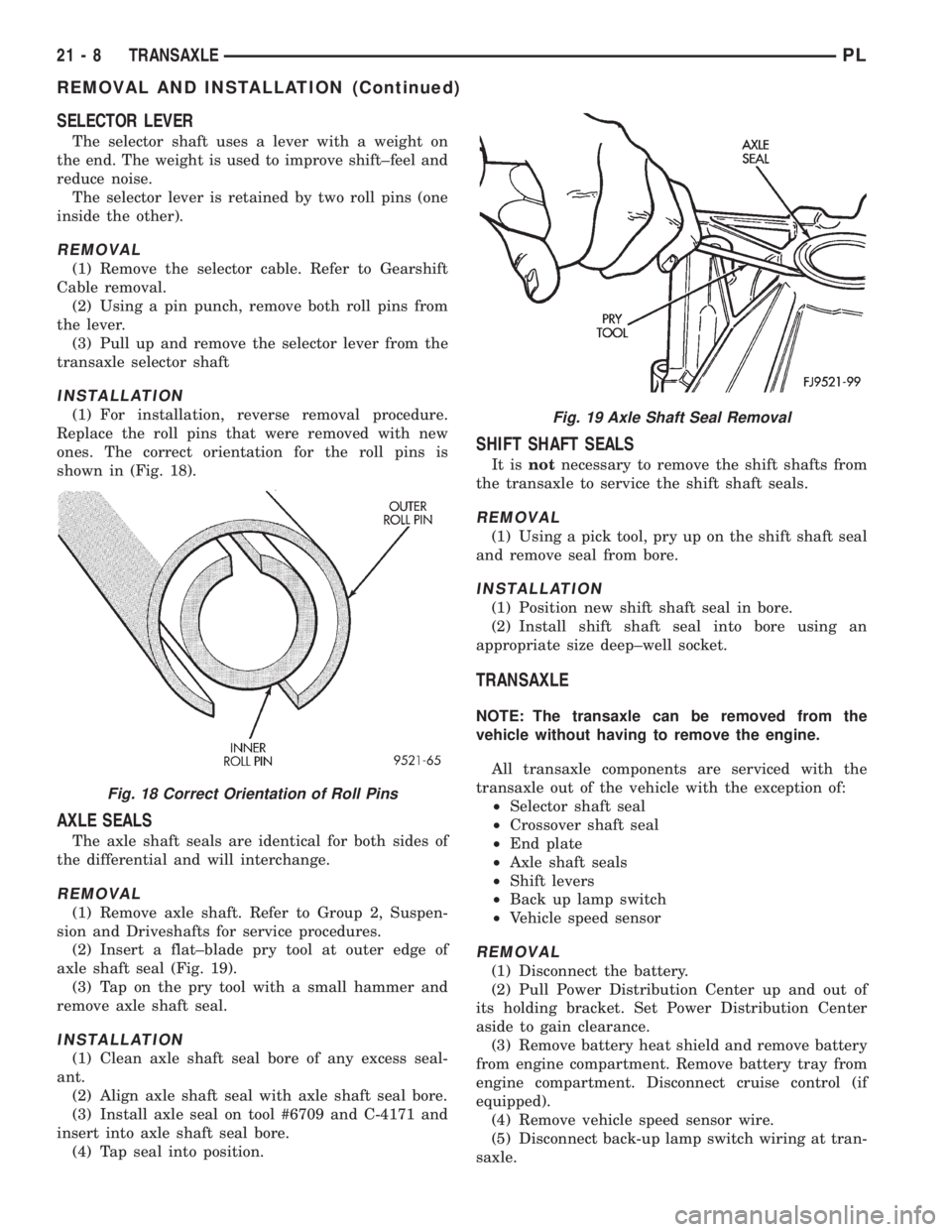
ones. The correct orientation for the roll pins is
shown in (Fig. 18).
AXLE SEALS
The axle shaft seals are identical for both sides of
the differential and will interchange.
REMOVAL
(1) Remove axle shaft. Refer to Group 2, Suspen-
sion and Driveshafts for service procedures.
(2) Insert a flat±blade pry tool at outer edge of
axle shaft seal (Fig. 19).
(3) Tap on the pry tool with a small hammer and
remove axle shaft seal.
INSTALLATION
(1) Clean axle shaft seal bore of any excess seal-
ant.
(2) Align axle shaft seal with axle shaft seal bore.
(3) Install axle seal on tool #6709 and C-4171 and
insert into axle shaft seal bore.
(4) Tap seal into position.
SHIFT SHAFT SEALS
It isnotnecessary to remove the shift shafts from
the transaxle to service the shift shaft seals.
REMOVAL
(1) Using a pick tool, pry up on the shift shaft seal
and remove seal from bore.
INSTALLATION
(1) Position new shift shaft seal in bore.
(2) Install shift shaft seal into bore using an
appropriate size deep±well socket.
TRANSAXLE
NOTE: The transaxle can be removed from the
vehicle without having to remove the engine.
All transaxle components are serviced with the
transaxle out of the vehicle with the exception of:
²Selector shaft seal
²Crossover shaft seal
²End plate
²Axle shaft seals
²Shift levers
²Back up lamp switch
²Vehicle speed sensor
REMOVAL
(1) Disconnect the battery.
(2) Pull Power Distribution Center up and out of
its holding bracket. Set Power Distribution Center
aside to gain clearance.
(3) Remove battery heat shield and remove battery
from engine compartment. Remove battery tray from
engine compartment. Disconnect cruise control (if
equipped).
(4) Remove vehicle speed sensor wire.
(5) Disconnect back-up lamp switch wiring at tran-
saxle.
Fig. 18 Correct Orientation of Roll Pins
Fig. 19 Axle Shaft Seal Removal
21 - 8 TRANSAXLEPL
REMOVAL AND INSTALLATION (Continued)
Page 1002 of 1200
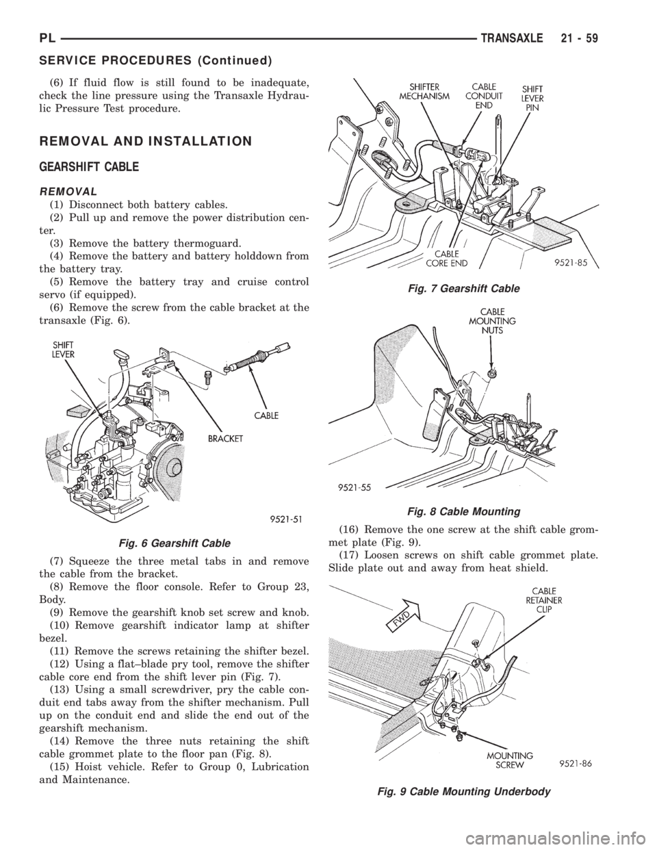
(6) If fluid flow is still found to be inadequate,
check the line pressure using the Transaxle Hydrau-
lic Pressure Test procedure.
REMOVAL AND INSTALLATION
GEARSHIFT CABLE
REMOVAL
(1) Disconnect both battery cables.
(2) Pull up and remove the power distribution cen-
ter.
(3) Remove the battery thermoguard.
(4) Remove the battery and battery holddown from
the battery tray.
(5) Remove the battery tray and cruise control
servo (if equipped).
(6) Remove the screw from the cable bracket at the
transaxle (Fig. 6).
(7) Squeeze the three metal tabs in and remove
the cable from the bracket.
(8) Remove the floor console. Refer to Group 23,
Body.
(9) Remove the gearshift knob set screw and knob.
(10) Remove gearshift indicator lamp at shifter
bezel.
(11) Remove the screws retaining the shifter bezel.
(12) Using a flat±blade pry tool, remove the shifter
cable core end from the shift lever pin (Fig. 7).
(13) Using a small screwdriver, pry the cable con-
duit end tabs away from the shifter mechanism. Pull
up on the conduit end and slide the end out of the
gearshift mechanism.
(14) Remove the three nuts retaining the shift
cable grommet plate to the floor pan (Fig. 8).
(15) Hoist vehicle. Refer to Group 0, Lubrication
and Maintenance.(16) Remove the one screw at the shift cable grom-
met plate (Fig. 9).
(17) Loosen screws on shift cable grommet plate.
Slide plate out and away from heat shield.
Fig. 6 Gearshift Cable
Fig. 7 Gearshift Cable
Fig. 8 Cable Mounting
Fig. 9 Cable Mounting Underbody
PLTRANSAXLE 21 - 59
SERVICE PROCEDURES (Continued)
Page 1007 of 1200
VEHICLE SPEED SENSOR PINION GEAR
When the sensor is removed for any reason, a
NEW O-ring must be installed on its outside diame-
ter.
REMOVAL
(1) Remove harness connector from sensor. Be sure
weather seal stays on harness connector.
(2) Remove bolt securing the sensor in the exten-
sion housing.
(3) Carefully pull sensor and pinion gear assembly
out of extension housing.
(4) Remove pinion gear from sensor.
INSTALLATION
(1) To install, reverse the above procedure. Be sure
extension housing and sensor flange are clean prior
to installation. Always use a NEW sensor O-ring.
(2) Tighten bolt to 7 N´m (60 in. lbs.). Tighten
speedometer cable to 4 N´m (35 in. lbs.).
PARK/NEUTRAL STARTING AND BACK-UP LAMP
SWITCH
TEST
The park/neutral starting switch is the center ter-
minal of the three terminal switch. It provides
ground for the starter solenoid circuit through the
selector lever in PARK and NEUTRAL positions only.
(1) To test switch, remove wiring connector from
switch and test for continuity between center pin of
switch and transaxle case. Continuity should exist
only when transaxle is in PARK or NEUTRAL.
(2) Check gearshift cable adjustment before replac-
ing a switch that tests bad.
REMOVAL
(1) Unscrew switch from transaxle case allowing
fluid to drain into a container. Move selector lever to
PARK, then to NEUTRAL position, and inspect to see
the switch operating lever fingers are centered in
switch opening.
INSTALLATION
(1) Screw the switch with a new seal into tran-
saxle case and tighten to 33 N´m (24 ft. lbs.). Retest
switch with the test lamp.
(2) Add fluid to transaxle to bring up to proper
level.
(3) The back-up lamp switch circuit is through the
two outside terminals of the three terminal switch.
(4) To test switch, remove wiring connector from
switch and test for continuity between the two out-
side pins.
(5) Continuity should exist only with transaxle in
REVERSE position.(6) No continuity should exist from either pin to
the case.
TRANSAXLE
REMOVAL
NOTE: The transaxle can be removed from the
vehicle without having to remove the engine.
The transaxle and torque converter must be
removed as an assembly; otherwise, the torque con-
verter drive plate, pump bushing, or oil seal may be
damaged. The drive plate will not support a load;
therefore, none of the weight of the transaxle should
be allowed to rest on the plate during removal.
All transaxle components are serviced with the
transaxle out of the vehicle. The components that are
serviceable in the vehicle are:
²Axle shaft seals
²Back±up lamp switch
²End plate
²Extension housing
²Neutral safety switch
²Shift lever
²Transaxle oil pan
²Valve Body
²Vehicle speed sensor
(1) Disconnect the battery.
(2) Pull Power Distribution Center up and out of
its holding bracket. Set Power Distribution Center
aside to gain clearance.
(3) Remove battery heat shield and remove battery
from engine compartment. Remove battery tray from
engine compartment. Disconnect cruise control (if
equipped).
(4) Remove vehicle speed sensor wiring.
(5) Disconnect neutral safety switch and torque
converter control wiring at transaxle.
CAUTION: Pry up with equal force on both sides of
shifter cable isolator bushing to avoid damaging
cable isolator bushing.
(6) Disconnect gear shift cable end from transaxle
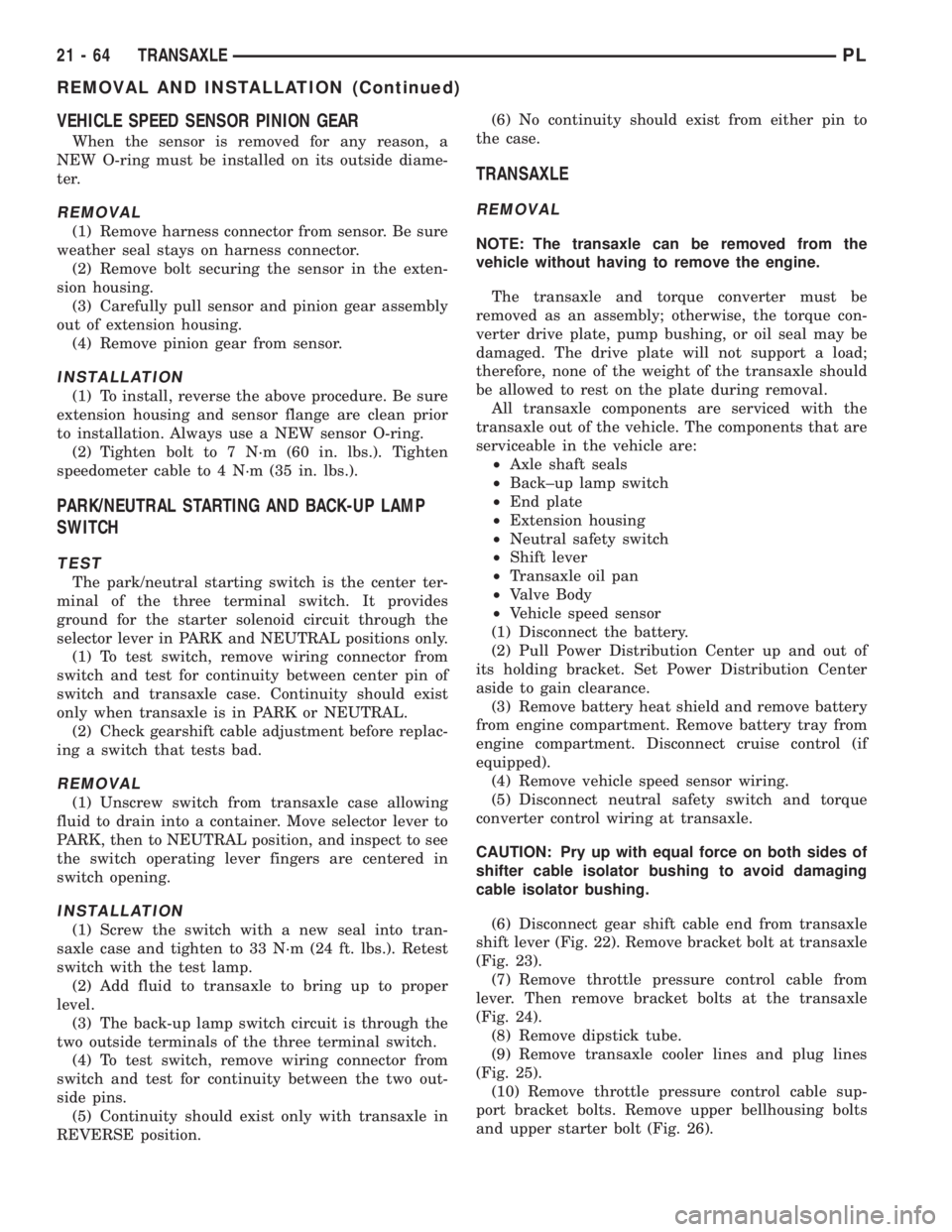
shift lever (Fig. 22). Remove bracket bolt at transaxle
(Fig. 23).
(7) Remove throttle pressure control cable from
lever. Then remove bracket bolts at the transaxle
(Fig. 24).
(8) Remove dipstick tube.
(9) Remove transaxle cooler lines and plug lines
(Fig. 25).
(10) Remove throttle pressure control cable sup-
port bracket bolts. Remove upper bellhousing bolts
and upper starter bolt (Fig. 26).
21 - 64 TRANSAXLEPL
REMOVAL AND INSTALLATION (Continued)