warning DODGE NEON 1999 Service Repair Manual
[x] Cancel search | Manufacturer: DODGE, Model Year: 1999, Model line: NEON, Model: DODGE NEON 1999Pages: 1200, PDF Size: 35.29 MB
Page 8 of 1200
JUMP STARTING, TOWING AND HOISTING
INDEX
page page
SERVICE PROCEDURES
HOISTING RECOMMENDATIONS............ 9JUMP STARTING PROCEDURE.............. 7
TOWING RECOMMENDATIONS.............. 8
SERVICE PROCEDURES
JUMP STARTING PROCEDURE
WARNING: REVIEW ALL SAFETY PRECAUTIONS
AND WARNINGS IN GROUP 8A, BATTERY/START-
ING/CHARGING SYSTEMS DIAGNOSTICS. DO NOT
JUMP START A FROZEN BATTERY, PERSONAL
INJURY CAN RESULT. DO NOT JUMP START WHEN
MAINTENANCE FREE BATTERY INDICATOR DOT IS
YELLOW OR BRIGHT COLOR. DO NOT JUMP
START A VEHICLE WHEN THE BATTERY FLUID IS
BELOW THE TOP OF LEAD PLATES. DO NOT
ALLOW JUMPER CABLE CLAMPS TO TOUCH
EACH OTHER WHEN CONNECTED TO A BOOSTER
SOURCE. DO NOT USE OPEN FLAME NEAR BAT-
TERY. REMOVE METALLIC JEWELRY WORN ON
HANDS OR WRISTS TO AVOID INJURY BY ACCI-
DENTAL ARCING OF BATTERY CURRENT. WHEN
USING A HIGH OUTPUT BOOSTING DEVICE, DO
NOT ALLOW BATTERY VOLTAGE TO EXCEED 16
VOLTS. REFER TO INSTRUCTIONS PROVIDED
WITH DEVICE BEING USED.
CAUTION: When using another vehicle as a
booster, do not allow vehicles to touch. Electrical
systems can be damaged on either vehicle.
TO JUMP START A DISABLED VEHICLE:
(1) Raise hood on disabled vehicle and visually
inspect engine compartment for:
²Battery cable clamp condition, clean if necessary.
²Frozen battery.
²Yellow or bright color test indicator, if equipped.
²Low battery fluid level.
²Generator drive belt condition and tension.
²Fuel fumes or leakage, correct if necessary.
CAUTION: If the cause of starting problem on dis-
abled vehicle is severe, damage to booster vehicle
charging system can result.
(2) When using another vehicle as a booster
source, park the booster vehicle within cable reach.
Turn off all accessories, set the parking brake, placethe automatic transmission in PARK or the manual
transmission in NEUTRAL and turn the ignition
OFF.
(3) On disabled vehicle, place gear selector in park
or neutral and set park brake. Turn off all accesso-
ries.
(4) Connect jumper cables to booster battery. RED
clamp to positive terminal (+). BLACK clamp to neg-
ative terminal (-). DO NOT allow clamps at opposite
end of cables to touch, electrical arc will result.
Review all warnings in this procedure.
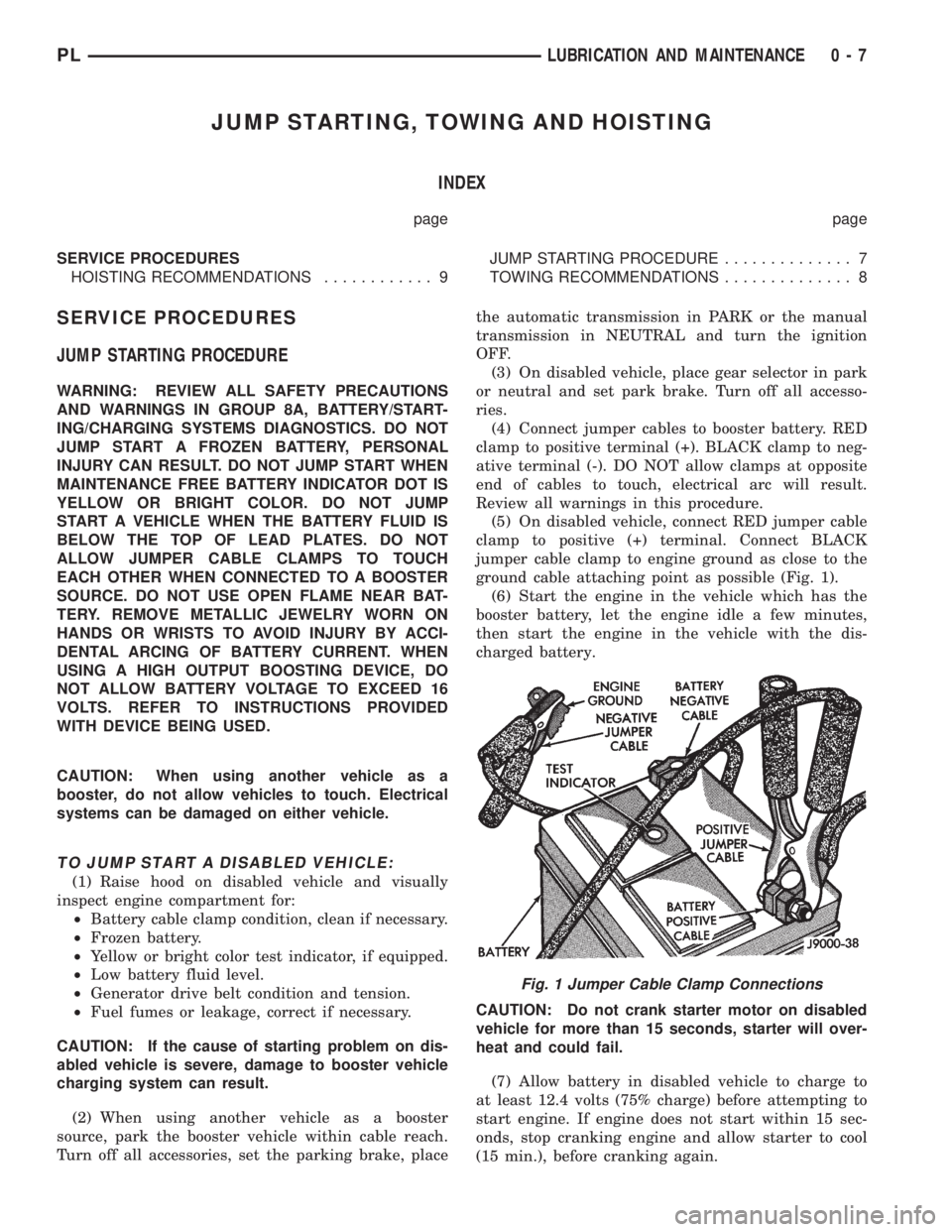
(5) On disabled vehicle, connect RED jumper cable
clamp to positive (+) terminal. Connect BLACK
jumper cable clamp to engine ground as close to the
ground cable attaching point as possible (Fig. 1).
(6) Start the engine in the vehicle which has the
booster battery, let the engine idle a few minutes,
then start the engine in the vehicle with the dis-
charged battery.
CAUTION: Do not crank starter motor on disabled
vehicle for more than 15 seconds, starter will over-
heat and could fail.
(7) Allow battery in disabled vehicle to charge to
at least 12.4 volts (75% charge) before attempting to
start engine. If engine does not start within 15 sec-
onds, stop cranking engine and allow starter to cool
(15 min.), before cranking again.
Fig. 1 Jumper Cable Clamp Connections
PLLUBRICATION AND MAINTENANCE 0 - 7
Page 9 of 1200
DISCONNECT CABLE CLAMPS AS FOLLOWS:
²Disconnect BLACK cable clamp from engine
ground on disabled vehicle.
²When using a Booster vehicle, disconnect
BLACK cable clamp from battery negative terminal.
Disconnect RED cable clamp from battery positive
terminal.
²Disconnect RED cable clamp from battery posi-
tive terminal on disabled vehicle.
TOWING RECOMMENDATIONS
WARNING: DO NOT ALLOW TOWING ATTACH-
MENT DEVICES TO CONTACT THE FUEL TANK OR
LINES, FUEL LEAK CAN RESULT. DO NOT LIFT OR
TOW VEHICLE BY FRONT OR REAR BUMPER, OR
BUMPER ENERGY ABSORBER UNITS. DO NOT
VENTURE UNDER A LIFTED VEHICLE IF NOT SUP-
PORTED PROPERLY ON SAFETY STANDS. DO NOT
ALLOW PASSENGERS TO RIDE IN A TOWED VEHI-
CLE. USE A SAFETY CHAIN THAT IS INDEPENDENT
FROM THE TOWING ATTACHMENT DEVICE.
CAUTION: Do not damage brake lines, exhaust
system, shock absorbers, sway bars, or any other
under vehicle components when attaching towing
device to vehicle. Do not attach towing device to
front or rear suspension components. Do not
secure vehicle to towing device by the use of front
or rear suspension or steering components.
Remove or secure loose or protruding objects from
a damaged vehicle before towing. Refer to state and
local rules and regulations before towing a vehicle.
Do not allow weight of towed vehicle to bear on
lower fascia, air dams, or spoilers.
RECOMMENDED TOWING EQUIPMENT
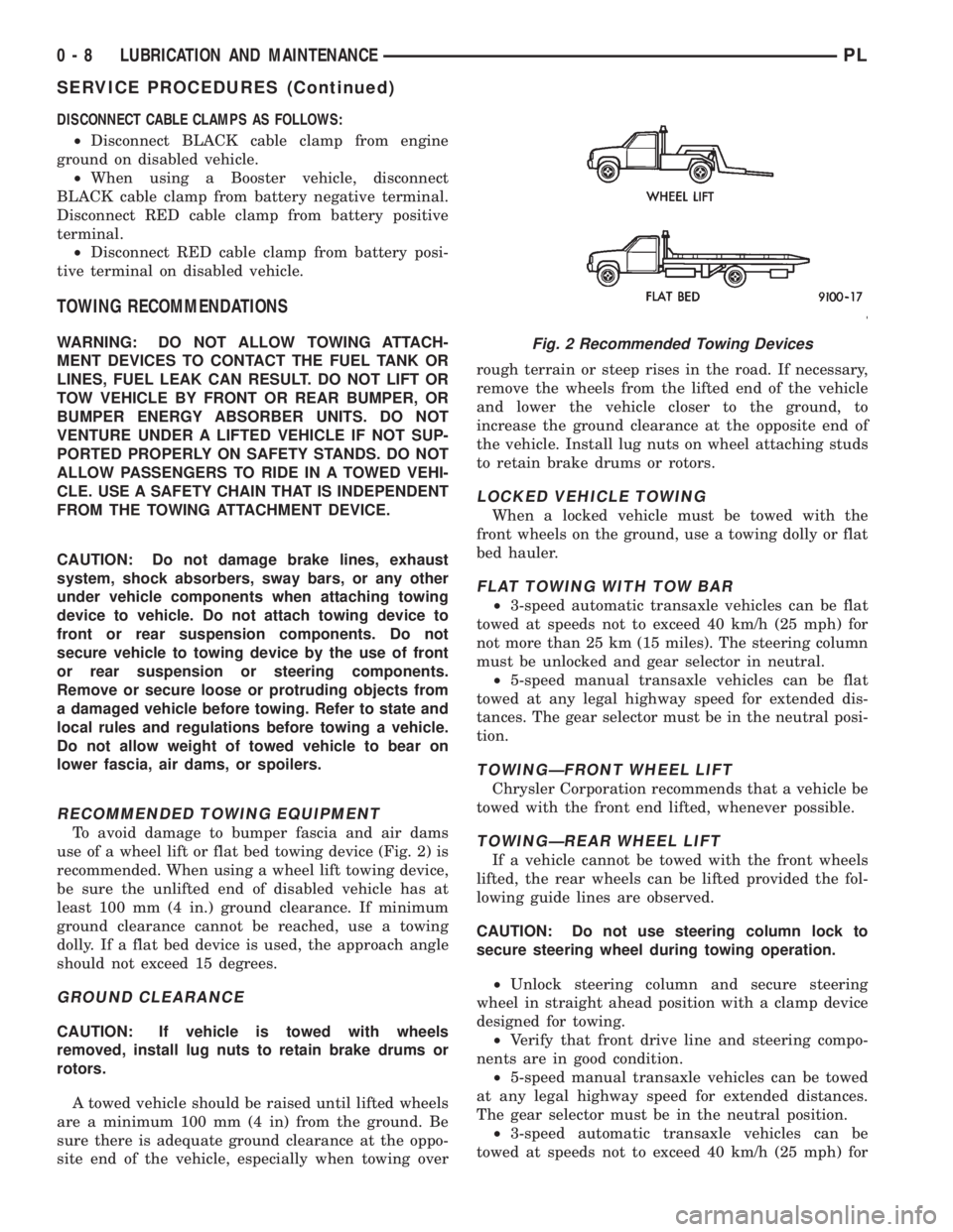
To avoid damage to bumper fascia and air dams
use of a wheel lift or flat bed towing device (Fig. 2) is
recommended. When using a wheel lift towing device,
be sure the unlifted end of disabled vehicle has at
least 100 mm (4 in.) ground clearance. If minimum
ground clearance cannot be reached, use a towing
dolly. If a flat bed device is used, the approach angle
should not exceed 15 degrees.
GROUND CLEARANCE
CAUTION: If vehicle is towed with wheels
removed, install lug nuts to retain brake drums or
rotors.
A towed vehicle should be raised until lifted wheels
are a minimum 100 mm (4 in) from the ground. Be
sure there is adequate ground clearance at the oppo-
site end of the vehicle, especially when towing overrough terrain or steep rises in the road. If necessary,
remove the wheels from the lifted end of the vehicle
and lower the vehicle closer to the ground, to
increase the ground clearance at the opposite end of
the vehicle. Install lug nuts on wheel attaching studs
to retain brake drums or rotors.
LOCKED VEHICLE TOWING
When a locked vehicle must be towed with the
front wheels on the ground, use a towing dolly or flat
bed hauler.
FLAT TOWING WITH TOW BAR
²3-speed automatic transaxle vehicles can be flat
towed at speeds not to exceed 40 km/h (25 mph) for
not more than 25 km (15 miles). The steering column
must be unlocked and gear selector in neutral.
²5-speed manual transaxle vehicles can be flat
towed at any legal highway speed for extended dis-
tances. The gear selector must be in the neutral posi-
tion.
TOWINGÐFRONT WHEEL LIFT
Chrysler Corporation recommends that a vehicle be
towed with the front end lifted, whenever possible.
TOWINGÐREAR WHEEL LIFT
If a vehicle cannot be towed with the front wheels
lifted, the rear wheels can be lifted provided the fol-
lowing guide lines are observed.
CAUTION: Do not use steering column lock to
secure steering wheel during towing operation.
²Unlock steering column and secure steering
wheel in straight ahead position with a clamp device
designed for towing.
²Verify that front drive line and steering compo-
nents are in good condition.
²5-speed manual transaxle vehicles can be towed
at any legal highway speed for extended distances.
The gear selector must be in the neutral position.
²3-speed automatic transaxle vehicles can be
towed at speeds not to exceed 40 km/h (25 mph) for
Fig. 2 Recommended Towing Devices
0 - 8 LUBRICATION AND MAINTENANCEPL
SERVICE PROCEDURES (Continued)
Page 10 of 1200
not more than 25 km (15 miles). The gear selector
must be in the neutral position.
HOISTING RECOMMENDATIONS
Refer to Owner's Manual provided with vehicle for
proper emergency jacking procedures.
WARNING: THE HOISTING AND JACK LIFTING
POINTS PROVIDED ARE FOR A COMPLETE VEHI-
CLE. WHEN THE ENGINE OR REAR SUSPENSION
IS REMOVED FROM A VEHICLE, THE CENTER OF
GRAVITY IS ALTERED MAKING SOME HOISTING
CONDITIONS UNSTABLE. PROPERLY SUPPORT OR
SECURE VEHICLE TO HOISTING DEVICE WHEN
THESE CONDITIONS EXIST.
CAUTION: Do not position hoisting device on sus-
pension components, damage to vehicle can result.
Do not attempt to raise one entire side of the
vehicle by placing a floor jack midway between the
front and rear wheels. This practice may result in
permanent damage to the body.
FLOOR JACK
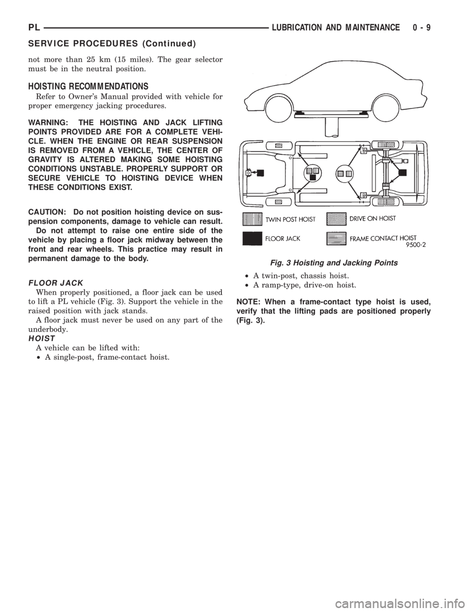
When properly positioned, a floor jack can be used
to lift a PL vehicle (Fig. 3). Support the vehicle in the
raised position with jack stands.
A floor jack must never be used on any part of the
underbody.
HOIST
A vehicle can be lifted with:
²A single-post, frame-contact hoist.²A twin-post, chassis hoist.
²A ramp-type, drive-on hoist.
NOTE: When a frame-contact type hoist is used,
verify that the lifting pads are positioned properly
(Fig. 3).
Fig. 3 Hoisting and Jacking Points
PLLUBRICATION AND MAINTENANCE 0 - 9
SERVICE PROCEDURES (Continued)
Page 27 of 1200
nent removal and installation sections in this group
of the service manual.
BALL JOINT ASSEMBLY
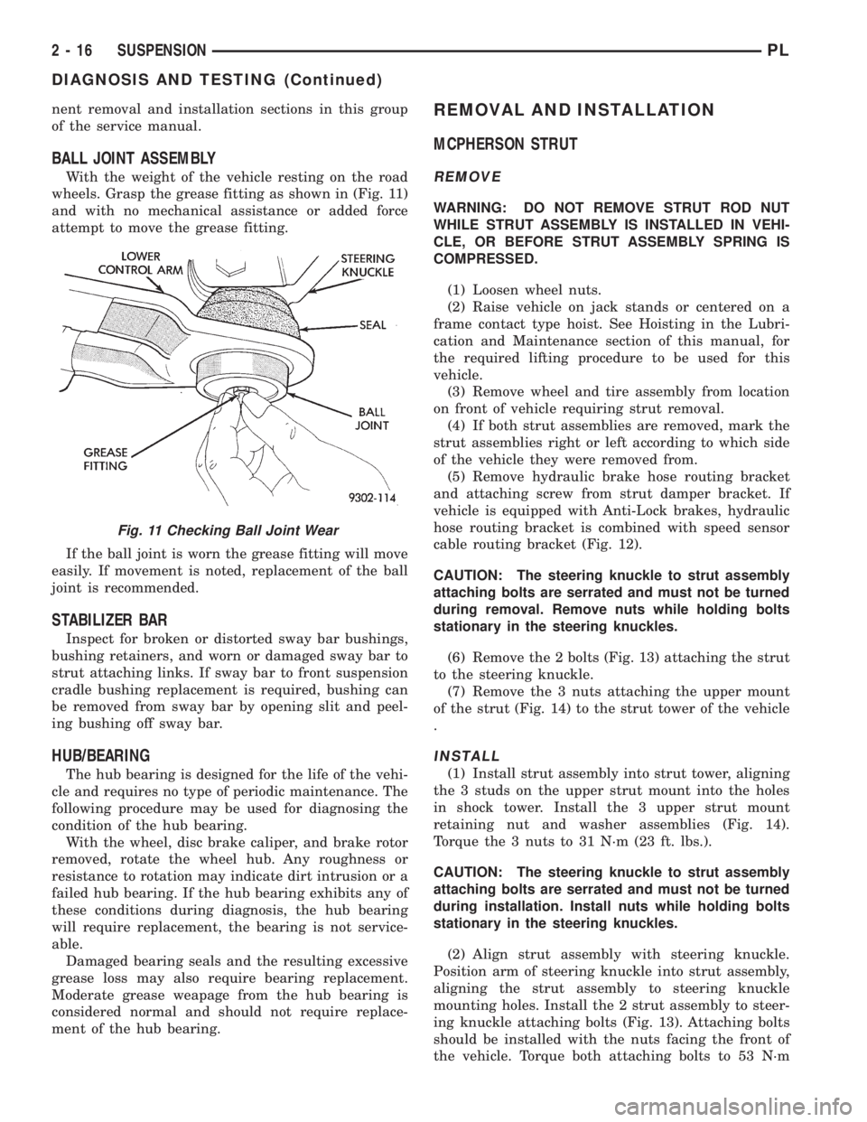
With the weight of the vehicle resting on the road
wheels. Grasp the grease fitting as shown in (Fig. 11)
and with no mechanical assistance or added force
attempt to move the grease fitting.
If the ball joint is worn the grease fitting will move
easily. If movement is noted, replacement of the ball
joint is recommended.
STABILIZER BAR
Inspect for broken or distorted sway bar bushings,
bushing retainers, and worn or damaged sway bar to
strut attaching links. If sway bar to front suspension
cradle bushing replacement is required, bushing can
be removed from sway bar by opening slit and peel-
ing bushing off sway bar.
HUB/BEARING
The hub bearing is designed for the life of the vehi-
cle and requires no type of periodic maintenance. The
following procedure may be used for diagnosing the
condition of the hub bearing.
With the wheel, disc brake caliper, and brake rotor
removed, rotate the wheel hub. Any roughness or
resistance to rotation may indicate dirt intrusion or a
failed hub bearing. If the hub bearing exhibits any of
these conditions during diagnosis, the hub bearing
will require replacement, the bearing is not service-
able.
Damaged bearing seals and the resulting excessive
grease loss may also require bearing replacement.
Moderate grease weapage from the hub bearing is
considered normal and should not require replace-
ment of the hub bearing.
REMOVAL AND INSTALLATION
MCPHERSON STRUT
REMOVE
WARNING: DO NOT REMOVE STRUT ROD NUT
WHILE STRUT ASSEMBLY IS INSTALLED IN VEHI-
CLE, OR BEFORE STRUT ASSEMBLY SPRING IS
COMPRESSED.
(1) Loosen wheel nuts.
(2) Raise vehicle on jack stands or centered on a
frame contact type hoist. See Hoisting in the Lubri-
cation and Maintenance section of this manual, for
the required lifting procedure to be used for this
vehicle.
(3) Remove wheel and tire assembly from location
on front of vehicle requiring strut removal.
(4) If both strut assemblies are removed, mark the
strut assemblies right or left according to which side
of the vehicle they were removed from.
(5) Remove hydraulic brake hose routing bracket
and attaching screw from strut damper bracket. If
vehicle is equipped with Anti-Lock brakes, hydraulic
hose routing bracket is combined with speed sensor
cable routing bracket (Fig. 12).
CAUTION: The steering knuckle to strut assembly
attaching bolts are serrated and must not be turned
during removal. Remove nuts while holding bolts
stationary in the steering knuckles.
(6) Remove the 2 bolts (Fig. 13) attaching the strut
to the steering knuckle.
(7) Remove the 3 nuts attaching the upper mount
of the strut (Fig. 14) to the strut tower of the vehicle
.
INSTALL
(1) Install strut assembly into strut tower, aligning
the 3 studs on the upper strut mount into the holes
in shock tower. Install the 3 upper strut mount
retaining nut and washer assemblies (Fig. 14).
Torque the 3 nuts to 31 N´m (23 ft. lbs.).
CAUTION: The steering knuckle to strut assembly
attaching bolts are serrated and must not be turned
during installation. Install nuts while holding bolts
stationary in the steering knuckles.
(2) Align strut assembly with steering knuckle.
Position arm of steering knuckle into strut assembly,
aligning the strut assembly to steering knuckle
mounting holes. Install the 2 strut assembly to steer-
ing knuckle attaching bolts (Fig. 13). Attaching bolts
should be installed with the nuts facing the front of
the vehicle. Torque both attaching bolts to 53 N´m
Fig. 11 Checking Ball Joint Wear
2 - 16 SUSPENSIONPL
DIAGNOSIS AND TESTING (Continued)
Page 41 of 1200
(5) Install the disc brake caliper to steering
knuckle attaching bolts (Fig. 61). Tighten the attach-
ing bolts to a torque of 31 N´m (23 ft. lbs.).
(6) Install front wheel and tire. Install front wheel
lug nuts and torque to 135 N´m
(7) (100 ft. lbs.).
(8) Lower vehicle.
DISASSEMBLY AND ASSEMBLY
McPHERSON STRUT
DISASSEMBLY
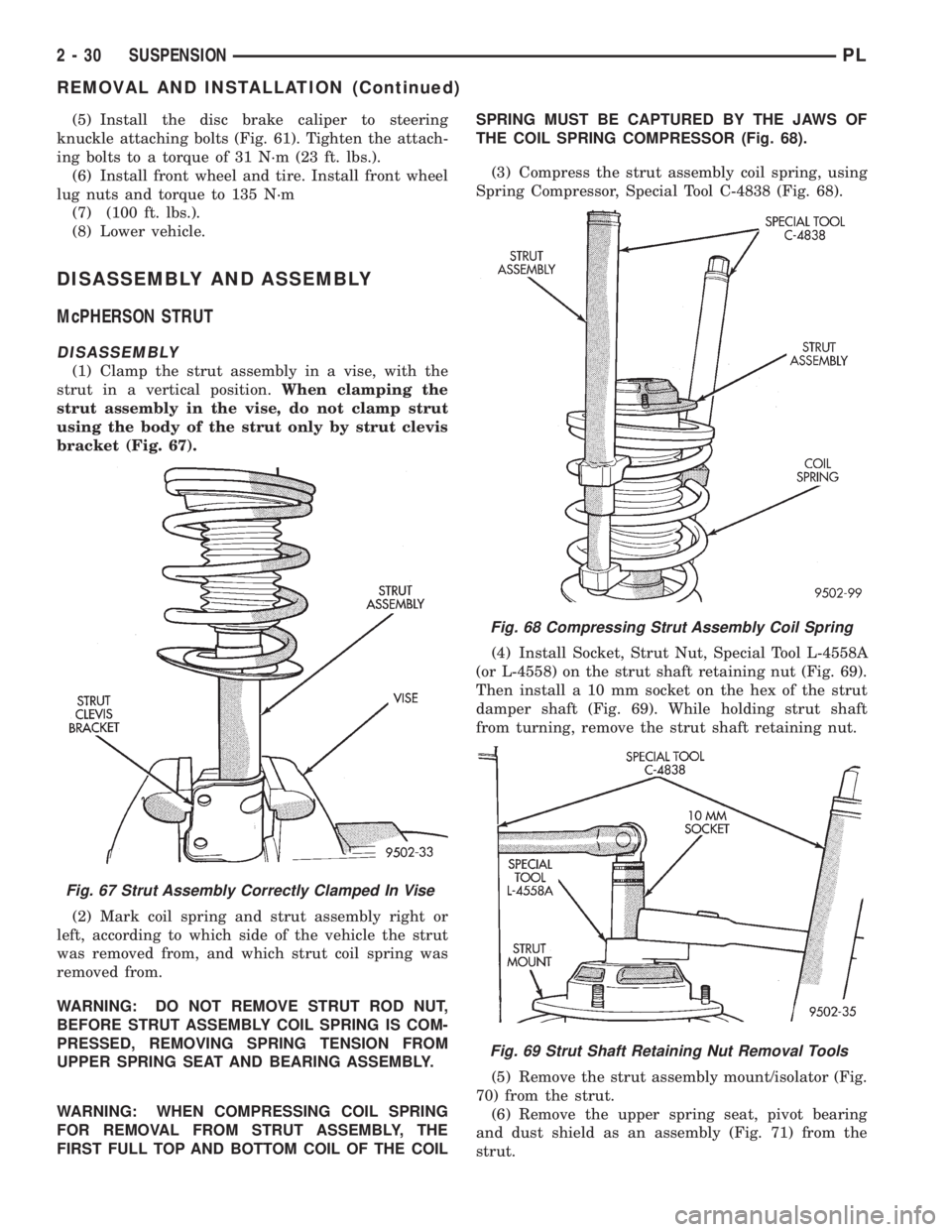
(1) Clamp the strut assembly in a vise, with the
strut in a vertical position.When clamping the
strut assembly in the vise, do not clamp strut
using the body of the strut only by strut clevis
bracket (Fig. 67).
(2) Mark coil spring and strut assembly right or
left, according to which side of the vehicle the strut
was removed from, and which strut coil spring was
removed from.
WARNING: DO NOT REMOVE STRUT ROD NUT,
BEFORE STRUT ASSEMBLY COIL SPRING IS COM-
PRESSED, REMOVING SPRING TENSION FROM
UPPER SPRING SEAT AND BEARING ASSEMBLY.
WARNING: WHEN COMPRESSING COIL SPRING
FOR REMOVAL FROM STRUT ASSEMBLY, THE
FIRST FULL TOP AND BOTTOM COIL OF THE COILSPRING MUST BE CAPTURED BY THE JAWS OF
THE COIL SPRING COMPRESSOR (Fig. 68).
(3) Compress the strut assembly coil spring, using
Spring Compressor, Special Tool C-4838 (Fig. 68).
(4) Install Socket, Strut Nut, Special Tool L-4558A
(or L-4558) on the strut shaft retaining nut (Fig. 69).
Then install a 10 mm socket on the hex of the strut
damper shaft (Fig. 69). While holding strut shaft
from turning, remove the strut shaft retaining nut.
(5) Remove the strut assembly mount/isolator (Fig.
70) from the strut.
(6) Remove the upper spring seat, pivot bearing
and dust shield as an assembly (Fig. 71) from the
strut.
Fig. 67 Strut Assembly Correctly Clamped In Vise
Fig. 68 Compressing Strut Assembly Coil Spring
Fig. 69 Strut Shaft Retaining Nut Removal Tools
2 - 30 SUSPENSIONPL
REMOVAL AND INSTALLATION (Continued)
Page 42 of 1200
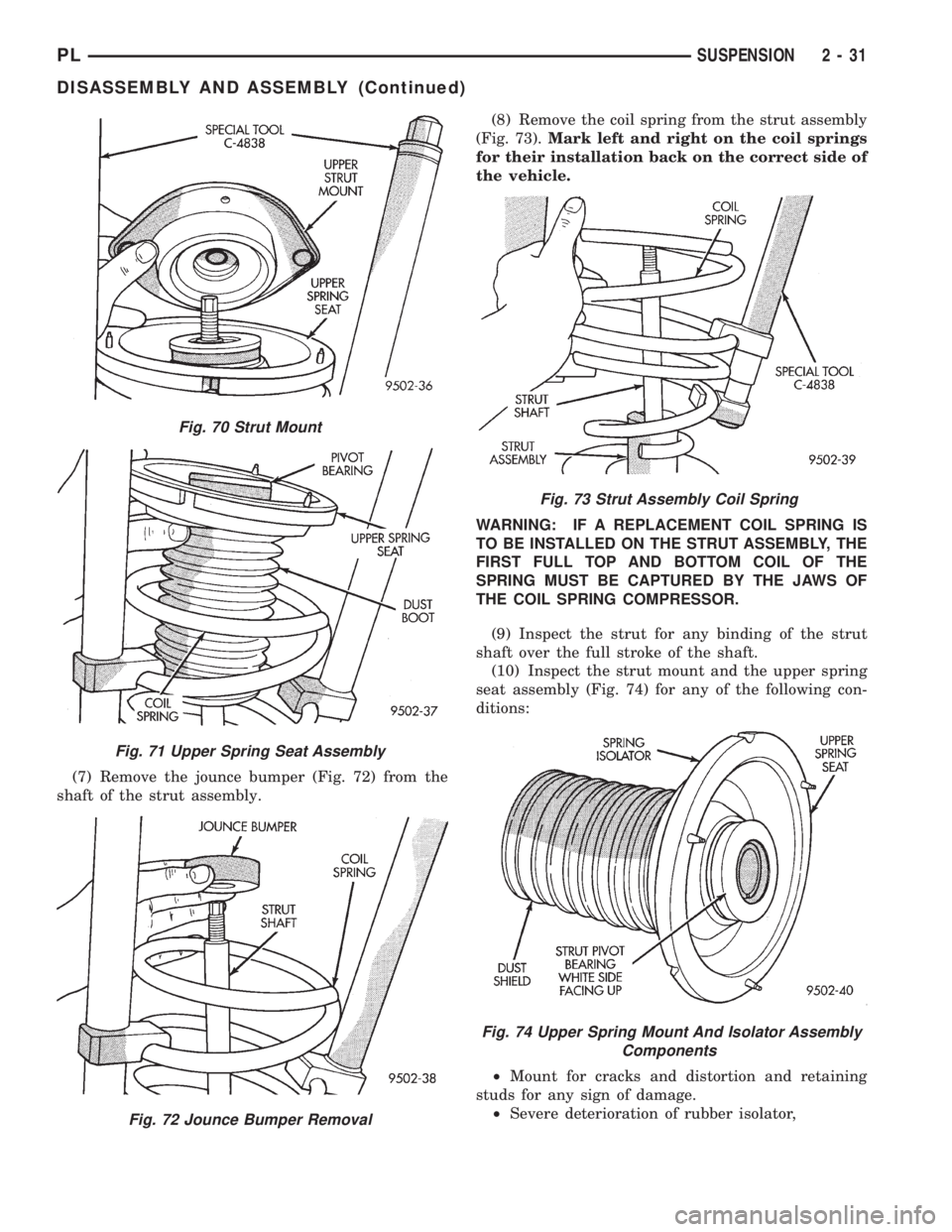
(7) Remove the jounce bumper (Fig. 72) from the
shaft of the strut assembly.(8) Remove the coil spring from the strut assembly
(Fig. 73).Mark left and right on the coil springs
for their installation back on the correct side of
the vehicle.
WARNING: IF A REPLACEMENT COIL SPRING IS
TO BE INSTALLED ON THE STRUT ASSEMBLY, THE
FIRST FULL TOP AND BOTTOM COIL OF THE
SPRING MUST BE CAPTURED BY THE JAWS OF
THE COIL SPRING COMPRESSOR.
(9) Inspect the strut for any binding of the strut
shaft over the full stroke of the shaft.
(10) Inspect the strut mount and the upper spring
seat assembly (Fig. 74) for any of the following con-
ditions:
²Mount for cracks and distortion and retaining
studs for any sign of damage.
²Severe deterioration of rubber isolator,
Fig. 70 Strut Mount
Fig. 71 Upper Spring Seat Assembly
Fig. 72 Jounce Bumper Removal
Fig. 73 Strut Assembly Coil Spring
Fig. 74 Upper Spring Mount And Isolator Assembly
Components
PLSUSPENSION 2 - 31
DISASSEMBLY AND ASSEMBLY (Continued)
Page 43 of 1200
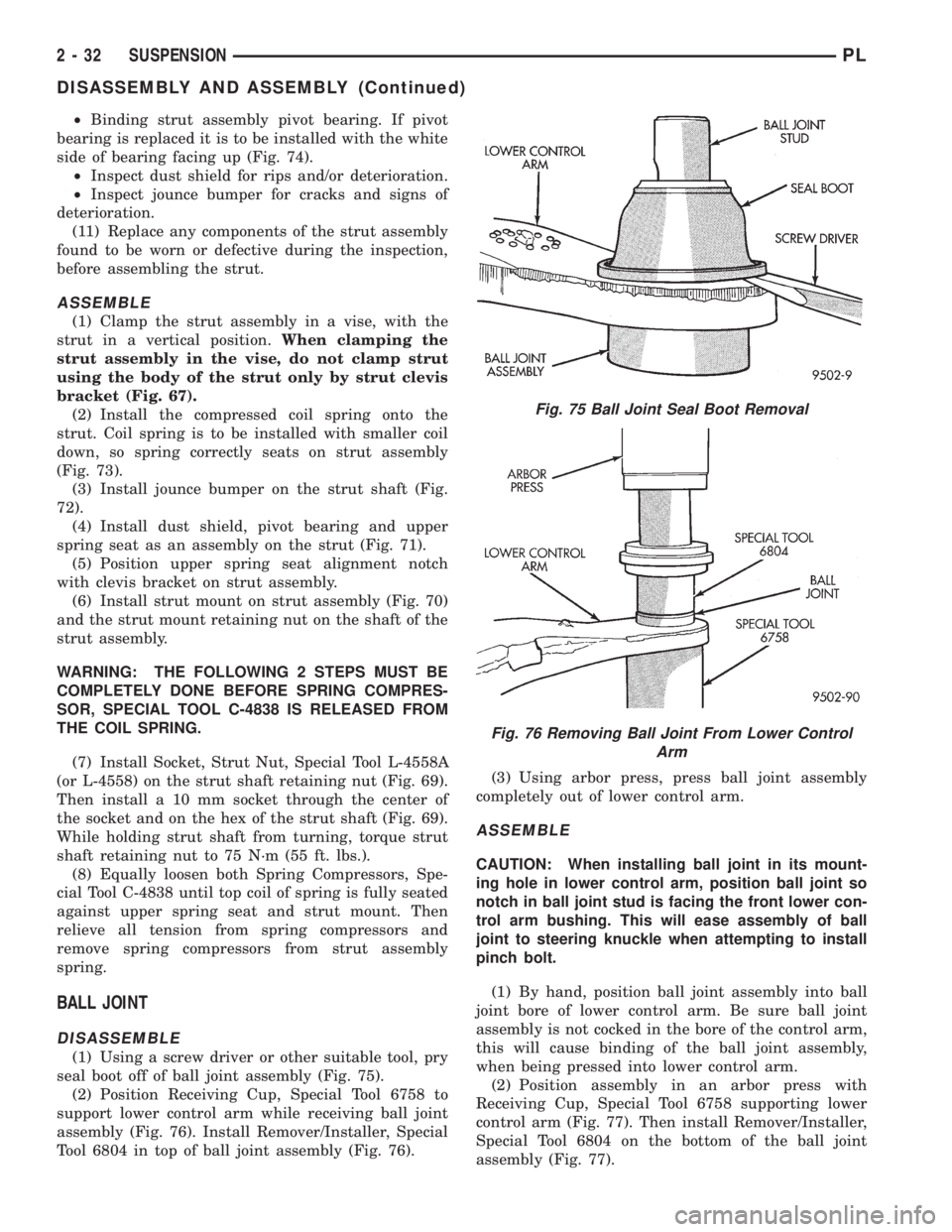
²Binding strut assembly pivot bearing. If pivot
bearing is replaced it is to be installed with the white
side of bearing facing up (Fig. 74).
²Inspect dust shield for rips and/or deterioration.
²Inspect jounce bumper for cracks and signs of
deterioration.
(11) Replace any components of the strut assembly
found to be worn or defective during the inspection,
before assembling the strut.
ASSEMBLE
(1) Clamp the strut assembly in a vise, with the
strut in a vertical position.When clamping the
strut assembly in the vise, do not clamp strut
using the body of the strut only by strut clevis
bracket (Fig. 67).
(2) Install the compressed coil spring onto the
strut. Coil spring is to be installed with smaller coil
down, so spring correctly seats on strut assembly
(Fig. 73).
(3) Install jounce bumper on the strut shaft (Fig.
72).
(4) Install dust shield, pivot bearing and upper
spring seat as an assembly on the strut (Fig. 71).
(5) Position upper spring seat alignment notch
with clevis bracket on strut assembly.
(6) Install strut mount on strut assembly (Fig. 70)
and the strut mount retaining nut on the shaft of the
strut assembly.
WARNING: THE FOLLOWING 2 STEPS MUST BE
COMPLETELY DONE BEFORE SPRING COMPRES-
SOR, SPECIAL TOOL C-4838 IS RELEASED FROM
THE COIL SPRING.
(7) Install Socket, Strut Nut, Special Tool L-4558A
(or L-4558) on the strut shaft retaining nut (Fig. 69).
Then install a 10 mm socket through the center of
the socket and on the hex of the strut shaft (Fig. 69).
While holding strut shaft from turning, torque strut
shaft retaining nut to 75 N´m (55 ft. lbs.).
(8) Equally loosen both Spring Compressors, Spe-
cial Tool C-4838 until top coil of spring is fully seated
against upper spring seat and strut mount. Then
relieve all tension from spring compressors and
remove spring compressors from strut assembly
spring.
BALL JOINT
DISASSEMBLE
(1) Using a screw driver or other suitable tool, pry
seal boot off of ball joint assembly (Fig. 75).
(2) Position Receiving Cup, Special Tool 6758 to
support lower control arm while receiving ball joint
assembly (Fig. 76). Install Remover/Installer, Special
Tool 6804 in top of ball joint assembly (Fig. 76).(3) Using arbor press, press ball joint assembly
completely out of lower control arm.
ASSEMBLE
CAUTION: When installing ball joint in its mount-
ing hole in lower control arm, position ball joint so
notch in ball joint stud is facing the front lower con-
trol arm bushing. This will ease assembly of ball
joint to steering knuckle when attempting to install
pinch bolt.
(1) By hand, position ball joint assembly into ball
joint bore of lower control arm. Be sure ball joint
assembly is not cocked in the bore of the control arm,
this will cause binding of the ball joint assembly,
when being pressed into lower control arm.
(2) Position assembly in an arbor press with
Receiving Cup, Special Tool 6758 supporting lower
control arm (Fig. 77). Then install Remover/Installer,
Special Tool 6804 on the bottom of the ball joint
assembly (Fig. 77).
Fig. 75 Ball Joint Seal Boot Removal
Fig. 76 Removing Ball Joint From Lower Control
Arm
2 - 32 SUSPENSIONPL
DISASSEMBLY AND ASSEMBLY (Continued)
Page 83 of 1200
BASE BRAKE SYSTEM
INDEX
page page
DESCRIPTION AND OPERATION
CHASSIS TUBES AND HOSES.............. 6
FRONT DISC BRAKES..................... 2
MASTER CYLINDER...................... 6
PARKING BRAKES........................ 4
PROPORTIONING VALVES................. 5
REAR DISC BRAKES...................... 4
REAR DRUM BRAKES..................... 4
REAR WHEEL HUB/BEARING............... 8
RED BRAKE WARNING LAMP............... 7
STOP LAMP SWITCH...................... 8
VACUUM BOOSTER...................... 6
DIAGNOSIS AND TESTING
BRAKE FLUID CONTAMINATION............ 19
BRAKE SYSTEM BASIC DIAGNOSIS GUIDE.... 9
BRAKE SYSTEM DIAGNOSIS CHARTS....... 10
DRUM BRAKE AUTOMATIC ADJUSTER....... 14
PROPORTIONING VALVES................ 16
RED BRAKE WARNING LAMP TEST......... 19
ROTOR THICKNESS AND RUNOUT.......... 14
STOP LAMP SWITCH TEST PROCEDURE..... 19
SERVICE PROCEDURES
BRAKE BLEEDING....................... 20
BRAKE DRUM MACHINING................ 23
BRAKE FLUID LEVEL CHECK.............. 19
BRAKE ROTOR MACHINING............... 22
BRAKE TUBE REPAIR.................... 25
MASTER CYLINDER BLEEDING............ 21
PARK BRAKE LEVER AUTO ADJUSTER
MECHANISM.......................... 23
REMOVAL AND INSTALLATION
CHASSIS TUBES AND HOSES.............. 47
FRONT DISC BRAKE CALIPER............. 26
FRONT DISC BRAKE SHOES.............. 28
MASTER CYLINDER..................... 41
PARK BRAKE CABLES.................... 50
PARK BRAKE LEVER ASSEMBLY........... 48PARK BRAKE LEVER OUTPUT CABLE....... 49
PARK BRAKE SHOES WITH REAR DISC
BRAKES............................. 55
PROPORTIONING VALVE (BASE BRAKES).... 47
REAR BRAKE DRUM..................... 34
REAR BRAKE SHOE SUPPORT PLATE....... 37
REAR BRAKE SHOES.................... 35
REAR BRAKE WHEEL CYLINDER........... 38
REAR DISC BRAKE CALIPER.............. 30
REAR DISC BRAKE SHOES................ 32
REAR HUB/BEARING..................... 39
STOP LAMP SWITCH..................... 57
VACUUM BOOSTER..................... 44
WHEEL AND TIRE ASSEMBLY.............. 26
DISASSEMBLY AND ASSEMBLY
BRAKE FLUID LEVEL SWITCH............. 58
BRAKE FLUID RESERVOIR................ 57
FRONT AND REAR DISC BRAKE CALIPER.... 58
WHEEL CYLINDER (REAR DRUM BRAKE).... 63
CLEANING AND INSPECTION
CHASSIS TUBES AND HOSES.............. 65
FRONT DISC BRAKES.................... 63
REAR DISC BRAKES..................... 64
REAR DRUM BRAKE WHEEL CYLINDER...... 65
REAR DRUM BRAKES.................... 64
REAR WHEEL HUB AND BEARING ASSEMBLY . 65
ADJUSTMENTS
PARK BRAKE ADJUSTMENT............... 66
REAR DRUM BRAKE SHOE ADJUSTMENT.... 65
STOP LAMP SWITCH..................... 65
SPECIFICATIONS
BRAKE ACTUATION SYSTEM.............. 67
BRAKE FASTENER TORQUE SPECIFICATIONS . 67
BRAKE FLUID.......................... 67
SPECIAL TOOLS
BASE BRAKE SYSTEM................... 68
DESCRIPTION AND OPERATION
FRONT DISC BRAKES
The front disc brakes (Fig. 1) and (Fig. 2) consists
of the following components:
²The driving hub
²Braking disc (rotor)
²Caliper assembly - single piston, floating type
²Brake shoes and linings
The double pin calipers are mounted directly to the
steering knuckles and use no adapter. The caliper ismounted to the steering knuckle using bushings,
sleeves and 2 guide pin bolts which thread directly
into bosses on the steering knuckle (Fig. 2) and (Fig.
3).
Two machined abutments on the steering knuckle
position the caliper. The guide pin bolts, sleeves and
bushings control the side to side movement of the
caliper. The piston seal is designed to pull the piston
back into the bore of the caliper when the brake
pedal is released. This maintains the proper brake
shoe to rotor clearance (Fig. 4).
5 - 2 BRAKESPL
Page 88 of 1200
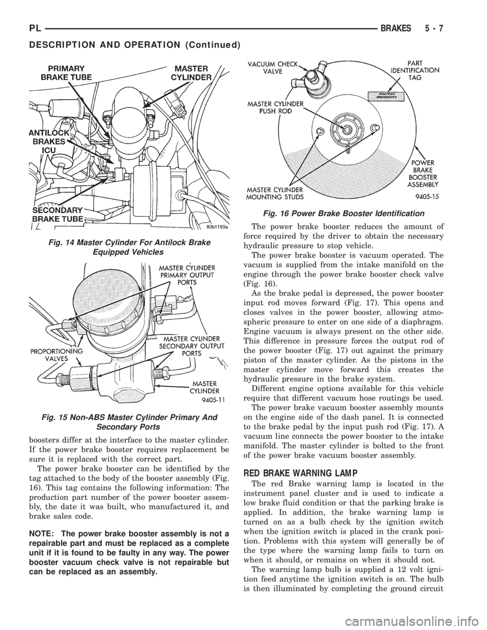
boosters differ at the interface to the master cylinder.
If the power brake booster requires replacement be
sure it is replaced with the correct part.
The power brake booster can be identified by the
tag attached to the body of the booster assembly (Fig.
16). This tag contains the following information: The
production part number of the power booster assem-
bly, the date it was built, who manufactured it, and
brake sales code.
NOTE: The power brake booster assembly is not a
repairable part and must be replaced as a complete
unit if it is found to be faulty in any way. The power
booster vacuum check valve is not repairable but
can be replaced as an assembly.The power brake booster reduces the amount of
force required by the driver to obtain the necessary
hydraulic pressure to stop vehicle.
The power brake booster is vacuum operated. The
vacuum is supplied from the intake manifold on the
engine through the power brake booster check valve
(Fig. 16).
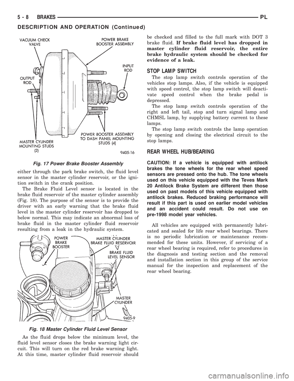
As the brake pedal is depressed, the power booster
input rod moves forward (Fig. 17). This opens and
closes valves in the power booster, allowing atmo-
spheric pressure to enter on one side of a diaphragm.
Engine vacuum is always present on the other side.
This difference in pressure forces the output rod of
the power booster (Fig. 17) out against the primary
piston of the master cylinder. As the pistons in the
master cylinder move forward this creates the
hydraulic pressure in the brake system.
Different engine options available for this vehicle
require that different vacuum hose routings be used.
The power brake vacuum booster assembly mounts
on the engine side of the dash panel. It is connected
to the brake pedal by the input push rod (Fig. 17). A
vacuum line connects the power booster to the intake
manifold. The master cylinder is bolted to the front
of the power brake vacuum booster assembly.
RED BRAKE WARNING LAMP
The red Brake warning lamp is located in the
instrument panel cluster and is used to indicate a
low brake fluid condition or that the parking brake is
applied. In addition, the brake warning lamp is
turned on as a bulb check by the ignition switch
when the ignition switch is placed in the crank posi-
tion. Problems with this system will generally be of
the type where the warning lamp fails to turn on
when it should, or remains on when it should not.
The warning lamp bulb is supplied a 12 volt igni-
tion feed anytime the ignition switch is on. The bulb
is then illuminated by completing the ground circuit
Fig. 14 Master Cylinder For Antilock Brake
Equipped Vehicles
Fig. 15 Non-ABS Master Cylinder Primary And
Secondary Ports
Fig. 16 Power Brake Booster Identification
PLBRAKES 5 - 7
DESCRIPTION AND OPERATION (Continued)
Page 89 of 1200
either through the park brake switch, the fluid level
sensor in the master cylinder reservoir, or the igni-
tion switch in the crank position.
The Brake Fluid Level sensor is located in the
brake fluid reservoir of the master cylinder assembly
(Fig. 18). The purpose of the sensor is to provide the
driver with an early warning that the brake fluid
level in the master cylinder reservoir has dropped to
below normal. This may indicate an abnormal loss of
brake fluid in the master cylinder fluid reservoir
resulting from a leak in the hydraulic system.
As the fluid drops below the minimum level, the
fluid level sensor closes the brake warning light cir-
cuit. This will turn on the red brake warning light.
At this time, master cylinder fluid reservoir shouldbe checked and filled to the full mark with DOT 3
brake fluid.If brake fluid level has dropped in
master cylinder fluid reservoir, the entire
brake hydraulic system should be checked for
evidence of a leak.
STOP LAMP SWITCH
The stop lamp switch controls operation of the
vehicles stop lamps. Also, if the vehicle is equipped
with speed control, the stop lamp switch will deacti-
vate speed control when the brake pedal is
depressed.
The stop lamp switch controls operation of the
right and left tail, stop and turn signal lamp and
CHMSL lamp, by supplying battery current to these
lamps.
The stop lamp switch controls the lamp operation
by opening and closing the electrical circuit to the
stop lamps.
REAR WHEEL HUB/BEARING
CAUTION: If a vehicle is equipped with antilock
brakes the tone wheels for the rear wheel speed
sensors are pressed onto the hub. The tone wheels
used on this vehicle equipped with the Teves Mark
20 Antilock Brake System are different then those
used on past models of this vehicle equipped with
antilock brakes. Reduced braking performance will
result if this part is used on earlier model vehicles
and an accident could result. Do not use on
pre-1998 model year vehicles.
All vehicles are equipped with permanently lubri-
cated and sealed for life rear wheel bearings. There
is no periodic lubrication or maintenance recom-
mended for these units. However, if servicing of a
rear wheel bearing is required, refer to procedures in
the diagnosis and testing section and the removal
and installation section in this group of the service
manual for the inspection and replacement of the
rear wheel bearing.Fig. 17 Power Brake Booster Assembly
Fig. 18 Master Cylinder Fluid Level Sensor
5 - 8 BRAKESPL
DESCRIPTION AND OPERATION (Continued)