fuse diagram DODGE NEON 2000 Service Owner's Manual
[x] Cancel search | Manufacturer: DODGE, Model Year: 2000, Model line: NEON, Model: DODGE NEON 2000Pages: 1285, PDF Size: 29.42 MB
Page 365 of 1285
first turn) will cause all vehicle doors to unlock elec-
trically. When this feature is disabled, all vehicle
doors will be unlocked electrically upon the first turn
of a key cylinder to the UNLOCK position. The vehi-
cle is locked electrically by turning the key cylinder
to the LOCK position once, regardless of the state of
the double activation unlock feature.
POWER DOOR LOCKS
The Remote Keyless Entry (RKE) Module actuates
the power door lock relays when a door lock switch is
activated. If the door lock switch is pressed for longer
than eight consecutive seconds, the RKE module will
de-energize the door lock motors.
The system includes the rolling door locking fea-
ture. The vehicle is shipped with the system enabled.
When the system is disabled the door locks will work
by use of the door lock switches and the Remote Key-
less Entry system only. When the rolling door lock
system is enabled, the RKE module will automati-
cally lock all the vehicle doors when all of the follow-
ing conditions are met:
²All doors are closed
²The vehicle speed exceeds 15 +/- 1 mph.
²The throttle position sensor tip-in is greater
than 10 +/- 2 degrees.
The RKE module will automatically re-lock all
doors if the above conditions are met and if any of
the doors become ajar and then closed again.
The enabling/disabling of the rolling door lock fea-
ture is customer programmable, as well as program-
mable with the DRB IIItscan tool.
The power lock motors are also equipped with a
thermal protection system which prevents the motors
from burning out. The motors may chatter if they are
continuously activated.
CHILD PROTECTION LOCKS
The child protection locks are on the rear doors
only. The lock, when engaged, will disable the inside
door handle from opening the door. The lock is part
of the latch/lock assembly. The lock is engaged by
moving a lever that is located on the rearward inside
edge of the door.
DOOR LOCK INHIBIT
With the key in the ignition switch and the driver
door open, the Remote Keyless Entry (RKE) Modulewill ignore the command to lock the power door locks
via the interior driver door lock switch. Once the key
is removed, or the driver door is closed, the RKE
module will allow the power door locks to lock via the
interior door lock switches.
DIAGNOSIS AND TESTING
DOOR LOCK MOTOR
(1) Make certain battery is in normal condition
and fuses powering the RKE module aren't blown
before circuits are tested.
(2) To determine which motor is faulty, check each
individual door for electrical lock and unlock or dis-
connect the motor connectors one at a time, while
operating the door lock switch.
(3) In the event that none of the motors work, the
problem maybe caused by a shorted motor, a bad
switch or a bad relay internal to the RKE module.
Disconnecting a defective motor will allow the others
to work.
(4) To test an individual door lock motor, discon-
nect the electrical connector from the motor.
(5) To lock the door, connect a 12 volt power source
to one pin of the lock motor and a ground wire to the
other pin.
(6) To unlock the door, reverse the wire connec-
tions at the motor pin terminals.
(7) If these results are NOT obtained, replace the
motor.
DOOR LOCK SWITCH
(1) Remove the switch from its mounting location,
and disconnect from vehicle wiring harness. Refer to
Door Lock Switch Removal and Installation in this
section.
(2) Using an ohmmeter, refer to Door Lock Switch
Resistance Test table to determine if switch resis-
tance is correct in the Lock and Unlock switch posi-
tions. Refer to Group 8W-Wiring Diagrams for
harness connector pin-outs.
DOOR LOCK SWITCH RESISTANCE
SWITCH POSITION CONTINUITY BETWEEN RESISTANCE VALUE
LOCK 2 AND 3 1000V
UNLOCK 2 AND 3 249V
8P - 2 POWER LOCK SYSTEMSPL
DESCRIPTION AND OPERATION (Continued)
Page 375 of 1285
memory to determine whether a valid key is in the
ignition lock cylinder.
The Sentry Key transponder cannot be repaired
and, if faulty or damaged, it must be replaced.
SENTRY KEY IMMOBILIZER SYSTEM
INDICATOR LAMP
The Sentry Key Immobilizer System (SKIS) uses
the Vehicle Theft Security System (VTSS) indicator
LED to give an indication when the SKIS is faulty or
when the vehicle has been immobilized due to the
use of an invalid ignition key. The LED is controlled
by the instrument cluster circuitry based upon mes-
sages received from the Sentry Key Immobilizer
Module (SKIM) through the Body Control Module
(BCM) on the Programmable Communication Inter-
face (PCI) bus.
The SKIM sends messages to the instrument clus-
ter, via the BCM, to turn the LED on for about three
seconds when the ignition switch is turned to the ON
position as a bulb test. After completion of the bulb
test, the SKIM sends PCI bus messages to keep the
LED off for a duration of about one second. Then the
SKIM sends messages to the instrument cluster cir-
cuitry to turn the LED on or off based upon the
results of the SKIS self-tests. If the VTSS indicator
LED comes on and stays on after the bulb test, it
indicates that the SKIM has detected a system mal-
function and/or that the SKIS has become inopera-
tive. If the SKIM detects an invalid key when the
ignition switch is turned to the ON position, it sends
messages to the instrument cluster to flash the VTSS
indicator LED.
The SKIM can also send messages to the instru-
ment cluster to flash the LED and to generate a sin-
gle audible chime tone. These functions serve as an
indication to the customer that the SKIS has been
placed in its ªCustomer Learnº programming mode.
See Sentry Key Immobilizer System Transponder
Programming in this group for more information on
the ªCustomer Learnº programming mode.
The VTSS indicator LED uses a replaceable Light
Emitting Diode (LED) on the instrument cluster elec-
tronic circuit board. Refer to Group 8E - Instrument
Panel Systems for Cluster Lamp Removal and Instal-
lation. If the VTSS indicator LED comes on and
stays on after the bulb test function, diagnosis of the
SKIS should be performed with a DRB IIItscan tool
and the proper Body Diagnostic Procedures Manual.
TRIGGERING THE VTSS
After the VTSS is armed, any of the following will
trigger the system:
²Opening any door.
²Opening the hood.
²Removing the trunk lock cylinder.²Turning the ignition to the RUN/START position
with an invalid Sentry Key.
NOTE: The ignition switch can be turned to the
accessory position without triggering the alarm sys-
tem.
DIAGNOSIS AND TESTING
SENTRY KEY IMMOBILIZER SYSTEM
WARNING: ON VEHICLES EQUIPPED WITH AIR-
BAGS, REFER TO GROUP 8M - PASSIVE
RESTRAINT SYSTEMS BEFORE ATTEMPTING ANY
STEERING WHEEL, STEERING COLUMN, OR
INSTRUMENT PANEL COMPONENT DIAGNOSIS OR
SERVICE. FAILURE TO TAKE THE PROPER PRE-
CAUTIONS COULD RESULT IN ACCIDENTAL AIR-
BAG DEPLOYMENT AND POSSIBLE PERSONAL
INJURY.
NOTE: The following tests may not prove conclu-
sive in the diagnosis of this system. The most reli-
able, efficient, and accurate means to diagnose the
Sentry Key Immobilizer System (SKIS) involves the
use of a DRB lllTscan tool and the proper Body
Diagnostic Procedures Manual.
The Sentry Key Immobilizer System (SKIS) and
the Programmable Communication Interface (PCI)
bus network should be diagnosed using a DRB lllt
scan tool. The DRB IIItwill allow confirmation that
the PCI bus is functional, that the Sentry Key Immo-
bilizer Module (SKIM) is placing the proper messages
on the PCI bus, and that the Powertrain Control
Module (PCM) and the instrument cluster are receiv-
ing the PCI bus messages. Refer to the proper Body
Diagnostic Procedures Manual. Refer to Group
8W-Wiring Diagrams for complete circuit descriptions
and diagrams.
(1) Check the fuses in the fuse block. If OK, go to
Step 2. If not OK, repair the shorted circuit or com-
ponent as required and replace the faulty fuse.
(2) Disconnect and isolate the battery negative
cable (Fig. 3). Unplug the wire harness connector at
the SKIM. Check for continuity between the ground
circuit cavity of the SKIM wire harness connector
and a good ground. There should be continuity. If
OK, go to Step 3. If not OK, repair the open circuit to
ground as required.
(3) Connect the battery negative cable. Check for
battery voltage at the fused B(+) circuit cavity of the
SKIM wire harness connector. If OK, go to Step 4. If
not OK, repair the open circuit to the fuse in the fuse
block as required.
8Q - 4 VEHICLE THEFT/SECURITY SYSTEMPL
DESCRIPTION AND OPERATION (Continued)
Page 380 of 1285
POWER WINDOWS
TABLE OF CONTENTS
page page
DESCRIPTION AND OPERATION
INTRODUCTION..........................1
DIAGNOSIS AND TESTING
WIRING TEST............................1
WINDOW SWITCH........................1WINDOW MOTOR.........................1
REMOVAL AND INSTALLATION
WINDOW SWITCH........................2
WINDOW MOTOR.........................2
DESCRIPTION AND OPERATION
INTRODUCTION
The window lift motors are of the permanent mag-
net type. A battery positive and negative connection
to either of the two motor terminals will cause the
motor to rotate in one direction. Reversing current
through these same two connections will cause the
motor to rotate in the opposite direction.
Each individual motor is grounded through the
master switch.
DIAGNOSIS AND TESTING
WIRING TEST
The following wiring test determines whether or
not voltage is continuous through the body harness
to the power window switches.
Remove switch for testing. Connect a voltmeter
positive lead to Pin 4 and negative lead to Pin 3 of
the switch harness connector. Turn ignition switch to
the ON position. Voltmeter should read battery volt-
age. If OK, go to Window Switch Diagnosis and Test-
ing. If not OK, check the 30 amp circuit breaker in
the fuse block or for a broken wire. Refer to Group
8W-Wiring Diagrams, for Connector Pin-Outs and
circuit descriptions.
WINDOW SWITCH
Remove the switch from its mounting, refer to Win-
dow Switch Removal and Installation in this section.
Using an ohmmeter, test the window switch for con-
tinuity in all positions Refer to Power Window
Switch Continuity table to determine if continuity is
correct. If the results are not obtained, replace the
switch.
WINDOW MOTOR
(1) Remove door trim panel. Refer to Group
23-Body, Front Door Trim Panel Removal and Instal-
lation.
(2) Connect positive (+) lead from a test battery to
either of the two motor terminals.
(3) Connect negative (-) lead from test battery to
remaining motor terminal.
(4) The motor should now rotate in one direction to
either move window up or down.
(a) If window happens to already be in full UP
position and motor is connected so as to move it in
UP direction no movement will be observed.
(b) Likewise, motor connected to move window
in DOWN direction no movement will be observed
if window is already in full DOWN position.
(c) Reverse battery leads in Step 2 and Step 3
and window should now move. If window does not
move, remove motor. Refer to Window Motor
Removal and Installation in this section.
(5) If window moved completely up or down, the
test leads should be reversed one more time to com-
plete a full window travel inspection.
POWER WINDOW SWITCH CONTINUITY
SWITCH POSITION CONTINUITY BETWEEN
OFF PIN 1 AND 4
PIN 2 AND 5
PIN 3 AND 8
UP PIN 1 AND 4
PIN 1 AND 8
PIN 2 AND 5
DOWN PIN 1 AND 4
PIN 1 AND 5
PIN 3 AND 8
PLPOWER WINDOWS 8S - 1
Page 382 of 1285
POWER MIRRORS
TABLE OF CONTENTS
page page
DESCRIPTION AND OPERATION
INTRODUCTION..........................1
DIAGNOSIS AND TESTING
MIRROR SWITCH TEST....................1
POWER MIRROR MOTOR..................2
REMOVAL AND INSTALLATION
INSIDE MIRROR/READING LAMPS
ASSEMBLY.............................2INSIDE MIRROR/READING LAMPS
BULB/LENS............................3
MIRROR SWITCH.........................3
POWER MIRROR ASSEMBLY................3
DESCRIPTION AND OPERATION
INTRODUCTION
Electrically operated power mirrors are available
on all car lines. The mirrors are controlled by a sin-
gle switch assembly located on the driver's door trim
panel. The push button rocker switch uses L (left)
and R (right) for mirror selection and a button to
push for the desired direction of mirror movement.
The motors which operate the mirrors are part of
the mirror assembly and cannot be replaced sepa-
rately.
The Ignition Off Draw fuse is included in the
power mirror circuity and should be checked if the
mirrors are inoperative.
DIAGNOSIS AND TESTING
MIRROR SWITCH TEST
(1) Remove power mirror switch from mounting
position. Refer to Mirror Switch Removal and Instal-
lation in this section.
(2) Using an ohmmeter, test for continuity between
the terminals of the switch as shown in the Mirror
Switch Continuity table.
(3) If test results are not obtained as shown in the
Mirror Switch Continuity table, replace the switch.
Refer to Group 8W-Wiring Diagrams for Connector
Pin-Outs and Circuit Diagrams.
PLPOWER MIRRORS 8T - 1
Page 386 of 1285
POWER MIRRORS
TABLE OF CONTENTS
page page
GENERAL INFORMATION
INTRODUCTION..........................1
DIAGNOSIS AND TESTING
POWER FOLD AWAY MIRROR SWITCH TEST...1POWER FOLD AWAY MIRROR MOTOR........1
REMOVAL AND INSTALLATION
POWER FOLD-AWAY MIRROR SWITCH.......1
POWER FOLD-AWAY MIRROR...............2
GENERAL INFORMATION
INTRODUCTION
These vehicles may be equipped with Power Fold
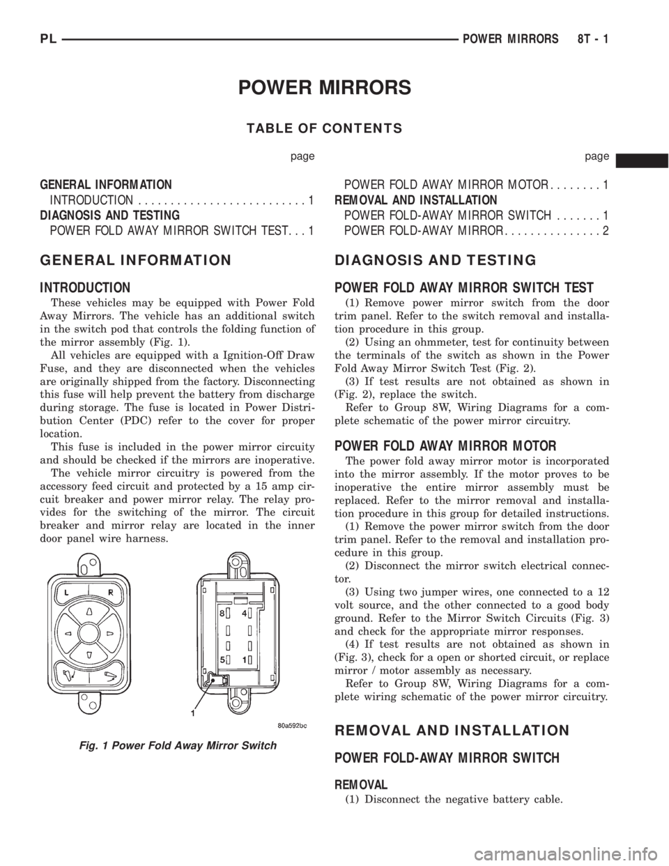
Away Mirrors. The vehicle has an additional switch
in the switch pod that controls the folding function of
the mirror assembly (Fig. 1).
All vehicles are equipped with a Ignition-Off Draw
Fuse, and they are disconnected when the vehicles
are originally shipped from the factory. Disconnecting
this fuse will help prevent the battery from discharge
during storage. The fuse is located in Power Distri-
bution Center (PDC) refer to the cover for proper
location.
This fuse is included in the power mirror circuity
and should be checked if the mirrors are inoperative.
The vehicle mirror circuitry is powered from the
accessory feed circuit and protected by a 15 amp cir-
cuit breaker and power mirror relay. The relay pro-
vides for the switching of the mirror. The circuit
breaker and mirror relay are located in the inner
door panel wire harness.
DIAGNOSIS AND TESTING
POWER FOLD AWAY MIRROR SWITCH TEST
(1) Remove power mirror switch from the door
trim panel. Refer to the switch removal and installa-
tion procedure in this group.
(2) Using an ohmmeter, test for continuity between
the terminals of the switch as shown in the Power
Fold Away Mirror Switch Test (Fig. 2).
(3) If test results are not obtained as shown in
(Fig. 2), replace the switch.
Refer to Group 8W, Wiring Diagrams for a com-
plete schematic of the power mirror circuitry.
POWER FOLD AWAY MIRROR MOTOR
The power fold away mirror motor is incorporated
into the mirror assembly. If the motor proves to be
inoperative the entire mirror assembly must be
replaced. Refer to the mirror removal and installa-
tion procedure in this group for detailed instructions.
(1) Remove the power mirror switch from the door
trim panel. Refer to the removal and installation pro-
cedure in this group.
(2) Disconnect the mirror switch electrical connec-
tor.
(3) Using two jumper wires, one connected to a 12
volt source, and the other connected to a good body
ground. Refer to the Mirror Switch Circuits (Fig. 3)
and check for the appropriate mirror responses.
(4) If test results are not obtained as shown in
(Fig. 3), check for a open or shorted circuit, or replace
mirror / motor assembly as necessary.
Refer to Group 8W, Wiring Diagrams for a com-
plete wiring schematic of the power mirror circuitry.
REMOVAL AND INSTALLATION
POWER FOLD-AWAY MIRROR SWITCH
REMOVAL
(1) Disconnect the negative battery cable.
Fig. 1 Power Fold Away Mirror Switch
PLPOWER MIRRORS 8T - 1
Page 392 of 1285
WIRING DIAGRAMS
TABLE OF CONTENTS
page page
AIR CONDITIONING-HEATER........... 8W-42-1
AIRBAG SYSTEM.................... 8W-43-1
ANTI-LOCK BRAKES.................. 8W-35-1
AUDIO SYSTEM..................... 8W-47-1
CHARGING SYSTEM.................. 8W-20-1
COMPONENT INDEX.................. 8W-02-1
CONNECTOR PIN-OUTS............... 8W-80-1
CONNECTOR/GROUND LOCATIONS...... 8W-90-1
FRONT LIGHTING.................... 8W-50-1
FUEL/IGNITION SYSTEM.............. 8W-30-1
FUSE BLOCK........................ 8W-11-1
GENERAL INFORMATION.............. 8W-01-1
GROUND DISTRIBUTION.............. 8W-15-1
HORN/CIGAR LIGHTER/POWER OUTLET . . 8W-41-1
INSTRUMENT CLUSTER............... 8W-40-1INTERIOR LIGHTING.................. 8W-44-1
POWER DISTRIBUTION............... 8W-10-1
POWER DOOR LOCKS................ 8W-61-1
POWER MIRRORS................... 8W-62-1
POWER SUNROOF................... 8W-64-1
POWER WINDOWS................... 8W-60-1
REAR LIGHTING..................... 8W-51-1
REAR WINDOW DEFOGGER............ 8W-48-1
SPLICE INFORMATION................ 8W-70-1
SPLICE LOCATIONS.................. 8W-95-1
STARTING SYSTEM.................. 8W-21-1
TURN SIGNALS...................... 8W-52-1
VEHICLE THEFT SECURITY SYSTEM..... 8W-39-1
WIPERS............................ 8W-53-1
PLWIRING DIAGRAMS 8W - 1
Page 397 of 1285
CIRCUIT INFORMATION
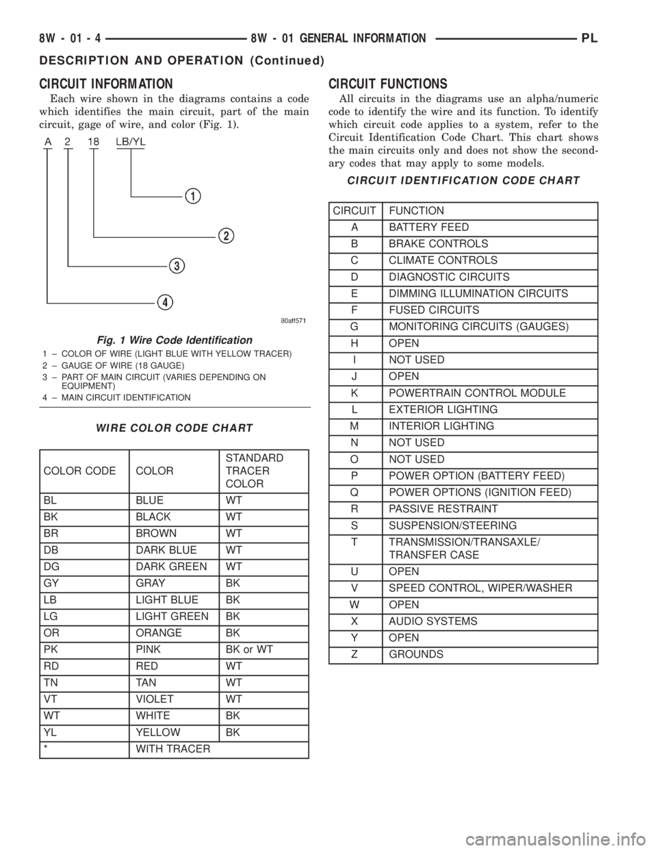
Each wire shown in the diagrams contains a code
which identifies the main circuit, part of the main
circuit, gage of wire, and color (Fig. 1).
CIRCUIT FUNCTIONS
All circuits in the diagrams use an alpha/numeric
code to identify the wire and its function. To identify
which circuit code applies to a system, refer to the
Circuit Identification Code Chart. This chart shows
the main circuits only and does not show the second-
ary codes that may apply to some models.
Fig. 1 Wire Code Identification
1 ± COLOR OF WIRE (LIGHT BLUE WITH YELLOW TRACER)
2 ± GAUGE OF WIRE (18 GAUGE)
3 ± PART OF MAIN CIRCUIT (VARIES DEPENDING ON
EQUIPMENT)
4 ± MAIN CIRCUIT IDENTIFICATION
WIRE COLOR CODE CHART
COLOR CODE COLORSTANDARD
TRACER
COLOR
BL BLUE WT
BK BLACK WT
BR BROWN WT
DB DARK BLUE WT
DG DARK GREEN WT
GY GRAY BK
LB LIGHT BLUE BK
LG LIGHT GREEN BK
OR ORANGE BK
PK PINK BK or WT
RD RED WT
TN TAN WT
VT VIOLET WT
WT WHITE BK
YL YELLOW BK
* WITH TRACER
CIRCUIT IDENTIFICATION CODE CHART
CIRCUIT FUNCTION
A BATTERY FEED
B BRAKE CONTROLS
C CLIMATE CONTROLS
D DIAGNOSTIC CIRCUITS
E DIMMING ILLUMINATION CIRCUITS
F FUSED CIRCUITS
G MONITORING CIRCUITS (GAUGES)
H OPEN
I NOT USED
J OPEN
K POWERTRAIN CONTROL MODULE
L EXTERIOR LIGHTING
M INTERIOR LIGHTING
N NOT USED
O NOT USED
P POWER OPTION (BATTERY FEED)
Q POWER OPTIONS (IGNITION FEED)
R PASSIVE RESTRAINT
S SUSPENSION/STEERING
T TRANSMISSION/TRANSAXLE/
TRANSFER CASE
U OPEN
V SPEED CONTROL, WIPER/WASHER
W OPEN
X AUDIO SYSTEMS
Y OPEN
Z GROUNDS
8W - 01 - 4 8W - 01 GENERAL INFORMATIONPL
DESCRIPTION AND OPERATION (Continued)
Page 402 of 1285
²Connectors are fully seated
²Spread terminals, or terminal push out
²Terminals in the wiring assembly are fully
seated into the connector/component and locked in
position
²Dirt or corrosion on the terminals. Any amount
of corrosion or dirt could cause an intermittent prob-
lem
²Damaged connector/component casing exposing
the item to dirt and moisture
²Wire insulation that has rubbed through causing
a short to ground
²Some or all of the wiring strands broken inside
of the insulation covering
²Wiring broken inside of the insulation.
TROUBLESHOOTING TESTS
Before beginning any tests on a vehicles electrical
system use the Wiring Diagrams and study the cir-
cuit. Also refer to the Troubleshooting Wiring Prob-
lems in this section.
TESTING FOR VOLTAGE POTENTIAL
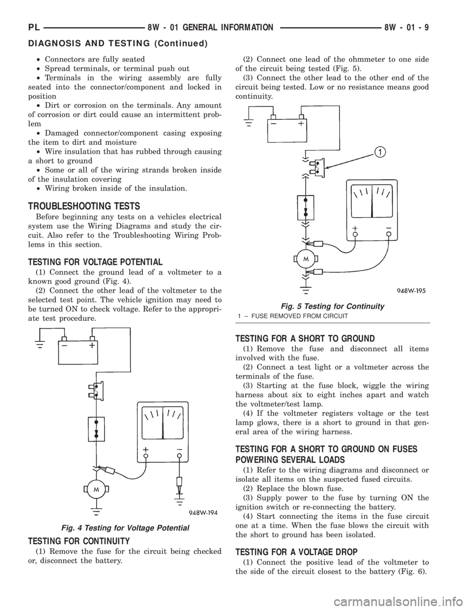
(1) Connect the ground lead of a voltmeter to a
known good ground (Fig. 4).
(2) Connect the other lead of the voltmeter to the
selected test point. The vehicle ignition may need to
be turned ON to check voltage. Refer to the appropri-
ate test procedure.
TESTING FOR CONTINUITY
(1) Remove the fuse for the circuit being checked
or, disconnect the battery.(2) Connect one lead of the ohmmeter to one side
of the circuit being tested (Fig. 5).
(3) Connect the other lead to the other end of the
circuit being tested. Low or no resistance means good
continuity.
TESTING FOR A SHORT TO GROUND
(1) Remove the fuse and disconnect all items
involved with the fuse.
(2) Connect a test light or a voltmeter across the
terminals of the fuse.
(3) Starting at the fuse block, wiggle the wiring
harness about six to eight inches apart and watch
the voltmeter/test lamp.
(4) If the voltmeter registers voltage or the test
lamp glows, there is a short to ground in that gen-
eral area of the wiring harness.
TESTING FOR A SHORT TO GROUND ON FUSES
POWERING SEVERAL LOADS
(1) Refer to the wiring diagrams and disconnect or
isolate all items on the suspected fused circuits.
(2) Replace the blown fuse.
(3) Supply power to the fuse by turning ON the
ignition switch or re-connecting the battery.
(4) Start connecting the items in the fuse circuit
one at a time. When the fuse blows the circuit with
the short to ground has been isolated.
TESTING FOR A VOLTAGE DROP
(1) Connect the positive lead of the voltmeter to
the side of the circuit closest to the battery (Fig. 6).
Fig. 4 Testing for Voltage Potential
Fig. 5 Testing for Continuity
1 ± FUSE REMOVED FROM CIRCUIT
PL8W - 01 GENERAL INFORMATION 8W - 01 - 9
DIAGNOSIS AND TESTING (Continued)
Page 859 of 1285
Like all Hall-effect sensors, the electronics of the
sensor needs a power source. This power source is
provided by the PCM. It is the same 8 volt power
supply that is used by the CKP and CMP sensors.
The vehicle speed sensor generates 8 pulses per
sensor revolution. This signal, in conjunction with a
closed throttle signal from the throttle position sen-
sor, indicates a closed throttle deceleration to the
PCM. Under deceleration conditions, the PCM
adjusts the Idle Air Control (IAC) motor to maintain
a desired MAP value.
When the vehicle is stopped at idle, a closed throt-
tle signal is received by the PCM (but a speed sensor
signal is not received). Under idle conditions, the
PCM adjusts the IAC motor to maintain a desired
engine speed.
AIR CONDITIONING CLUTCH RELAYÐPCM
OUTPUT
DESCRIPTION
The air conditioning clutch relay is located in the
PDC. The inside top of the PDC cover has a label
showing relay and fuse location.
OPERATION
The PCM controls the air conditioning clutch relay
ground circuit. The A/C clutch relay coil side contains
a 10 amp fuse between the buss bar in the Power
Distribution Center (PDC) and the relay. The power
side of this relay is fused with a 40 amp fuse. When
the PCM receives an air conditioning input, it
grounds the A/C compressor clutch relay and the
radiator fan relay.
When the PCM senses low idle speeds or wide open
throttle through the throttle position sensor, it
removes the ground for the A/C compressor clutch
relay. When the relay de-energizes, the contacts open
preventing air conditioning clutch engagement. Also,
if the PCM senses a part throttle launch condition, it
disables the A/C compressor clutch for several sec-
onds.
AUTOMATIC SHUTDOWN RELAYÐPCM
OUTPUT
DESCRIPTION
The ASD relay is located in the PDC. The inside
top of the PDC cover has a label showing relay and
fuse location.
OPERATION
The automatic shutdown (ASD) relay supplies bat-
tery voltage to the fuel injectors, electronic ignition
coil and the heating elements in the oxygen sensors
generator field and PCM sense circuit.A buss bar in the power distribution center (PDC)
supplies voltage to the solenoid side and contact side
of the relay. The ASD relay power circuit contains a
fuse between the buss bar in the PDC and the relay.
The fuse also protects the power circuit for the fuel
pump relay and pump. The fuse is located in the
PDC. Refer to the Wiring Diagrams for circuit infor-
mation.
The PCM controls the relay by switching the
ground path for the solenoid side of the relay on and
off. The PCM turns the ground path off when the
ignition switch is in the Off position unless the 02
Heater Monitor test is being run. When the ignition
switch is in the On or Crank position, the PCM mon-
itors the crankshaft position sensor and camshaft
position sensor signals to determine engine speed
and ignition timing (coil dwell). If the PCM does not
receive the crankshaft position sensor and camshaft
position sensor signals when the ignition switch is in
the Run position, it will de-energize the ASD relay.
CHARGING SYSTEM INDICATOR LAMPÐPCM
OUTPUT
OPERATION
The PCM turns the instrument panel Charging
System Lamp on. Refer to the Charging system sec-
tion information.
FUEL PUMP RELAYÐPCM OUTPUT
DESCRIPTION
The fuel pump relay is located in the PDC. The
inside top of the PDC cover has a label showing relay
and fuse location.
OPERATION
The fuel pump relay supplies battery voltage to the
fuel pump. A buss bar in the Power Distribution Cen-
ter (PDC) supplies voltage to the solenoid side and
contact side of the relay. The fuel pump relay power
circuit contains a fuse between the buss bar in the
PDC and the relay. The fuse also protects the power
circuit for the Automatic Shutdown (ASD) relay. The
fuse is located in the PDC. Refer to the Wiring Dia-
grams for circuit information.
The PCM controls the fuel pump relay by switch-
ing the ground path for the solenoid side of the relay
on and off. The PCM turns the ground path off when
the ignition switch is in the Off position. When the
ignition switch is in the On position, the PCM ener-
gizes the fuel pump. If the crankshaft position sensor
does not detect engine rotation, the PCM de-ener-
gizes the relay after approximately one second.
14 - 38 FUEL SYSTEMPL
DESCRIPTION AND OPERATION (Continued)
Page 1242 of 1285
BLOWER MOTOR VIBRATION AND/OR NOISE
DIAGNOSIS
The resistor block supplies the blower motor with
varied voltage (low and middle speeds) or battery
voltage (high speed).
CAUTION: Stay clear of the blower motor and resis-
tor block (Hot). Do not operate the blower motor
with the resistor block removed from the heater-A/C
housing.
Refer to the Blower Motor Vibration/Noise chart
for diagnosis.
COMPRESSOR NOISE DIAGNOSIS
Excessive noise while the A/C is being used, can be
caused by loose mounts, loose clutch, or high operat-
ing pressure. Verify compressor drive belt condition,
proper refrigerant charge and head pressure before
compressor repair is performed.
If the A/C drive belt slips at initial start-up, it does
not necessarily mean the compressor has failed.
With the close tolerances of a compressor it is pos-
sible to experience a temporary lockup. The longer
the A/C system is inactive, the more likely the condi-
tion to occur.
This condition is the result of normal refrigerant
movement within the A/C system caused by temper-
ature changes. The refrigerant movement may wash
the oil out of the compressor.
EVAPORATOR PROBE TEST
The work area and vehicle must be between 16É C
(60É F) and 32É C (90É F) when testing the switch.
(1) Disconnect the three wire connector from the
evaporator probe lead located behind the glove box
(Fig. 12).
(2) Start engine and set A/C to low blower motor
speed, panel, full cool, and RECIRC.
(3) Using a voltmeter, check for battery voltage
between Pin 1 and 2. If no voltage is detected, there
is no power to the switch. Check wiring and fuses.
Refer to Group 8W, Wiring Diagrams for circuit diag-
nosis.
(4) Using a voltmeter, check for battery voltage
between Pin 1 and Pin 3. If no voltage is detected,
there is no voltage from the Powertrain Control Mod-
ule. Refer to Group 8W, Wiring Diagrams. If voltage
is OK, connect a jumper wire between Pin 1 and Pin
3. The compressor clutch should engage. If the clutch
engages, remove the jumper wire immediately and go
to Step 5. If the compressor clutch does not engage,
check the operation of the clutch and repair as nec-
essary.(5) If compressor clutch engages, connect the evap-
orator probe 3-way connector. The compressor clutch
should engage or cycle depending on evaporator tem-
perature. If OK, go to Step 6. If not OK, replace the
clutch cycling switch.
(6) The engine running and the A/C set to:
²Blower motor on low speed
²Panel position
²Full cool
²RECIRC.
Close all doors and windows. Place a thermometer in
the center discharge vent.
(7) If the clutch does not begin to cycle off between
2É C to 7É C (35É F to 45É F), verify that the evapo-
rator probe is fully installed and not loose in evapo-
rator. If it is not properly installed, install probe and
retest outlet temperature. If the evaporator probe is
properly installed, replace the clutch cycling switch.
EXPANSION VALVE
NOTE: Expansion valve tests should be performed
after compressor tests.
Liquid CO2 is required to test the expansion
valve. It is available from most welding supply facil-
ities. CO2 is also available from companies which
service and sell fire extinguishers.
Review Safety Precautions and Warnings in the
General Information section of this Group. The work
area and vehicle must be 21É to 27ÉC (70É to 85ÉF)
when testing expansion valve. To test the expansion
valve:
(1) Connect a charging station or manifold gauge
set to the refrigerant system service ports.
(2) Disconnect wire connector at low pressure cut-
off switch (Fig. 13). Using a jumper wire, jump ter-
minals inside wire connector boot.
(3) Close all doors, windows and vents to the pas-
senger compartment.
(4) Set Heater-A/C control to A/C, full heat, floor,
RECIRC. and high blower.
(5) Start the engine and hold the idle speed (1000
rpm). After the engine has reached running temper-
ature, allow the passenger compartment to heat up.
This will create the need for maximum refrigerant
flow into the evaporator.
(6) If the refrigerant charge is sufficient, discharge
(high pressure) gauge should read 965 to 2620 kPa
(140 to 380 psi). Suction (low pressure) gauge should
read 103 to 2417 kPa (15 to 35 psi). If system cannot
achieve proper pressure readings, replace the expan-
sion valve. If pressure is correct, proceed with test.
PLHEATING AND AIR CONDITIONING 24 - 11
DIAGNOSIS AND TESTING (Continued)