maintenance schedule DODGE NEON 2000 Service Repair Manual
[x] Cancel search | Manufacturer: DODGE, Model Year: 2000, Model line: NEON, Model: DODGE NEON 2000Pages: 1285, PDF Size: 29.42 MB
Page 2 of 1285
LUBRICATION AND MAINTENANCE
TABLE OF CONTENTS
page page
LUBRICANTS............................. 1
MAINTENANCE SCHEDULES................. 3JUMP STARTING, TOWING, AND HOISTING..... 7
LUBRICANTS
TABLE OF CONTENTS
page page
DESCRIPTION AND OPERATION
PARTS AND LUBRICANT
RECOMMENDATIONS....................1
CLASSIFICATION OF LUBRICANTS............1
INTERNATIONAL SYMBOLS.................2FLUID CHECK/FILL POINTS AND
LUBRICATION LOCATIONS.................2
LUBRICATION POINT LOCATIONS............2
SPECIFICATIONS
FLUID CAPACITIES........................2
DESCRIPTION AND OPERATION
PARTS AND LUBRICANT RECOMMENDATIONS
When service is required, DaimlerChrysler Corpo-
ration recommends that only Mopartbrand parts,
lubricants and chemicals be used. Mopar provides
the best engineered products for servicing
DaimlerChrysler Corporation vehicles.
CLASSIFICATION OF LUBRICANTS
DESCRIPTION
Only lubricants bearing designations defined by
the following organization should be used to service a
DaimlerChrysler Corporation vehicle.
²Society of Automotive Engineers (SAE)
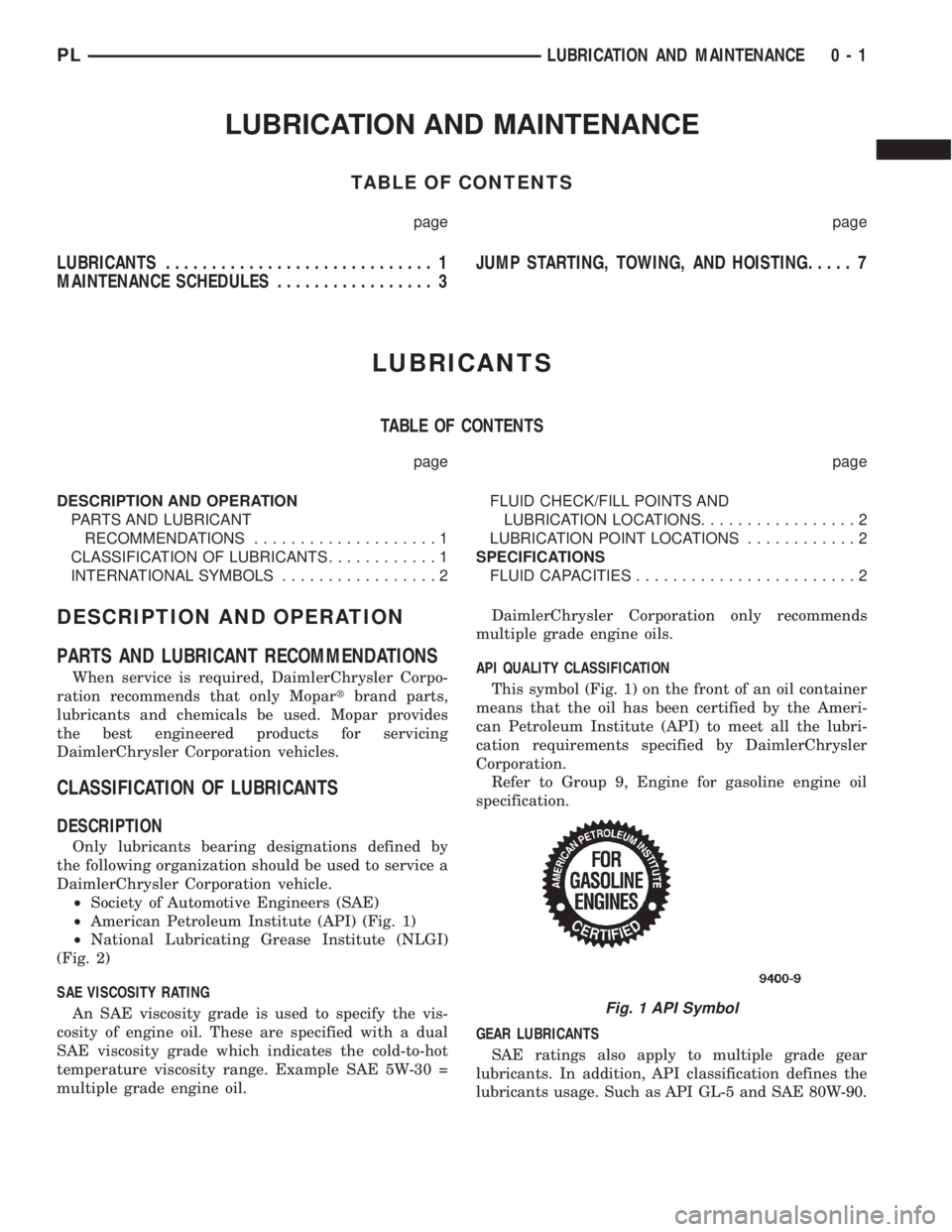
²American Petroleum Institute (API) (Fig. 1)
²National Lubricating Grease Institute (NLGI)
(Fig. 2)
SAE VISCOSITY RATING
An SAE viscosity grade is used to specify the vis-
cosity of engine oil. These are specified with a dual
SAE viscosity grade which indicates the cold-to-hot
temperature viscosity range. Example SAE 5W-30 =
multiple grade engine oil.DaimlerChrysler Corporation only recommends
multiple grade engine oils.
API QUALITY CLASSIFICATION
This symbol (Fig. 1) on the front of an oil container
means that the oil has been certified by the Ameri-
can Petroleum Institute (API) to meet all the lubri-
cation requirements specified by DaimlerChrysler
Corporation.
Refer to Group 9, Engine for gasoline engine oil
specification.
GEAR LUBRICANTS
SAE ratings also apply to multiple grade gear
lubricants. In addition, API classification defines the
lubricants usage. Such as API GL-5 and SAE 80W-90.
Fig. 1 API Symbol
PLLUBRICATION AND MAINTENANCE 0 - 1
Page 4 of 1285
MAINTENANCE SCHEDULES
TABLE OF CONTENTS
page page
DESCRIPTION AND OPERATION
MAINTENANCE SCHEDULES................3
SPECIFICATIONS
UNSCHEDULED INSPECTION................3SCHEDULE ± A...........................3
SCHEDULE ± B...........................4
DESCRIPTION AND OPERATION
MAINTENANCE SCHEDULES
There are two maintenance schedules that show
proper service for your vehicle.
First is Schedule ±A. It lists all the scheduled
maintenance to be performed under ªnormalº operat-
ing conditions.
Second is Schedule ±B. It is a schedule for vehi-
cles that are operated under the following conditions:
²Frequent short trip driving less than 5 miles (8
km)
²Frequent driving in dusty conditions
²Extensive idling
²More than 50% of the driving is at sustained
high speeds during hot weather, above 90É F (32É C)
SPECIFICATIONS
UNSCHEDULED INSPECTION
At Each Stop For Fuel
²Check engine oil level and add as required.
²Check windshield washer solvent and add as
required.
Once A Month
²Check tire pressure and look for unusual wear
or damage.
²Inspect the battery and clean and tighten termi-
nals as required.
²Check fluid levels of coolant reservoir, brake
master cylinder, power steering and transmission.
Add fluid as required.
²Check all lights and all other electrical items for
correct operation.
At Each Oil Change
²Inspect the exhaust system.
²Inspect brake hoses.
²Inspect the CV joints and front suspension com-
ponent boots and seals.²Rotate the tires at each oil change interval
shown on Schedule ± A (7,500 miles - 12 000 km) or
every other interval on Schedule ± B (6,000 miles -
10 000 km).
²Check the engine coolant level, hoses, and
clamps.
If mileage is less than 7,500 miles (12 000 km)
yearly, replace the engine oil filter at each oil change.
EMISSION CONTROL SYSTEM MAINTENANCE
The scheduled emission maintenance listed inbold
typeon the Maintenance Schedules, must be done at
the mileage specified to assure the continued proper
functioning of the emission control system. These,
and all other maintenance services included in this
manual, should be done to provide the best vehicle
performance and reliability. More frequent mainte-
nance may be needed for vehicles in severe operating
conditions such as dusty areas and very short trip
driving.
FLUID FILL POINTS AND LUBRICATION
LOCATIONS
The fluid fill/check locations and lubrication loca-
tions are located in each applicable group.
SCHEDULE ± A
7,500 Miles (12 000 km) or at 6 months
²Change the engine oil.
²Replace the engine oil filter.
15,000 Miles (24 000 km) or at 12 months
²Change the engine oil.
²Replace the engine oil filter.
²Adjust the drive belt tension.
22,500 Miles (36 000 km) or at 18 months
²Change the engine oil.
²Replace the engine oil filter.
²Inspect the front brake pads and rear brake lin-
ings.
PLLUBRICATION AND MAINTENANCE 0 - 3
Page 5 of 1285
30,000 Miles (48 000 km) or at 24 months
²Change the engine oil.
²Replace the engine oil filter.
²Lubricate the front suspension lower ball joint.
²Inspect the tie rod ends and boot seals.
²Adjust the drive belt tension.
²Replace the engine air cleaner element (fil-
ter).
²Replace the engine spark plugs
²Change the automatic transaxle fluid.
37,500 Miles (60 000 km) or at 30 months
²Change the engine oil.
²Replace the engine oil filter.
45,000 Miles (72 000 km) or at 36 months
²Change the engine oil.
²Replace the engine oil filter.
²Inspect the front brake pads and rear brake lin-
ings.
²Adjust the drive belt tension.
²Flush and replace the engine coolant at 36
months, regardless of mileage.
52,500 Miles (84 000 km) or at 42 months
²Change the engine oil.
²Replace the engine oil filter.
²Flush and replace the engine coolant if not done
at 36 months.
60,000 Miles (96 000 km) or at 48 months
²Change the engine oil.
²Replace the engine oil filter.
²Check the PCV valve and replace, if neces-
sary. Not required if previously changed.*
²Lubricate the front suspension lower ball joints.
²Replace the drive belts.
²Replace the engine air cleaner element (fil-
ter).
²Replace the ignition cables.
²Replace the spark plugs.
²Change the automatic transaxle fluid.
67,500 Miles (108 000 km) or at 54 months
²Change the engine oil.
²Replace the engine oil filter.
²Inspect the front brake pads and rear brake lin-
ings.
75,000 Miles (120 000 km) or at 60 months
²Change the engine oil.
²Replace the engine oil filter.
²Adjust the drive belt tension.
²Flush and replace engine coolant if has been
30,000 miles (48 000 km) or 24 months since last
change.
82,500 Miles (132 000 km) or at 66 months
²Change the engine oil.
²Replace the engine oil filter.
²Flush and replace engine coolant if it has been
30,000 miles (48 000 km) or 24 months since last
change.
90,000 Miles (144 000 km) or at 72 months
²Change the engine oil.
²Replace the engine oil filter.
²Check the PCV valve and replace, if neces-
sary. Not required if previously changed.*
²Lubricate the front suspension lower ball joints.
²Inspect the front brake pads and rear brake lin-
ings.
²Adjust the drive belt tension.
²Replace the engine air cleaner element (fil-
ter).
²Replace the spark plugs.
²Inspect the serpentine drive belt, replace if nec-
essary. This maintenance is not required if the belt
was previously replaced.
²Change the automatic transaxle fluid.
97,500 Miles (156 000 km) or at 78 months
²Change the engine oil.
²Replace the engine oil filter.
105,000 Miles (168 000 km) or at 84 months
²Change the engine oil.
²Replace the engine oil filter.
²Replace the engine timing belt.
²Adjust the drive belt tension.
*This maintenance is recommended by Daimler-
Chrysler Corporation to the owner but is not
required to maintain the emissions warranty.
NOTE: Inspection and service should also be per-
formed anytime a malfunction is observed or sus-
pected. Retain all receipts.
SCHEDULE ± B
3,000 Miles (5 000 km)
²Change the engine oil.
6,000 Miles (10 000 km)
²Change the engine oil.
²Replace the engine oil filter.
9,000 Miles (14 000 km)
²Change the engine oil.
²Inspect the front brake pads and rear brake lin-
ings.
0 - 4 LUBRICATION AND MAINTENANCEPL
SPECIFICATIONS (Continued)
Page 7 of 1285
69,000 Miles (110 000 km)
²Change the engine oil.
72,000 Miles (115 000 km)
²Change the engine oil.
²Replace the engine oil filter.
²Inspect the front brake pads and rear brake lin-
ings.
75,000 Miles (120 000 km)
²Change the engine oil.
²Adjust the drive belt tension.
²Inspect theengine air cleaner element (fil-
ter)and replace as necessary.*
²Change the automatic transaxle fluid/filter and
adjust bands.
78,000 Miles (125 000 km)
²Change the engine oil.
²Replace the engine oil filter.
81,000 Miles (130 000 km)
²Change the engine oil.
²Flush and replace the engine coolant.
²Inspect the front brake pads and rear brake lin-
ings.
84,000 Miles (134 000 km)
²Change the engine oil.
²Replace the engine oil filter.
87,000 Miles (139 000 km)
²Change the engine oil.
90,000 Miles (144 000 km)
²Change the engine oil.
²Replace the engine oil filter.
²Inspect front brake pads and rear brake linings
²Check thePCV valveand replace if necessary.
Not required if previously changed.*
²Lubricate the front suspension lower ball joint.
²Replace theengine air cleaner element (fil-
ter).²Replace thespark plugs
²Change the automatic transaxle fluid/filter and
adjust the bands.
93,000 Miles (149 000 km)
²Change the engine oil.
96,000 Miles (154 000 km)
²Change the engine oil.
²Replace the engine oil filter.
99,000 Miles (158 000 km)
²Change the engine oil.
²Inspect the front brake pads and rear brake lin-
ings.
102,000 Miles (163 000 km)
²Change the engine oil.
²Replace the engine oil filter.
105,000 Miles (168 000 km)
²Replace theengine timing belt.
²Change the engine oil.
²Adjust the drive belt tension.
²Inspect theengine air cleaner element (fil-
ter)and replace as necessary.*
²Change the automatic transaxle fluid/filter and
adjust the bands.
²Flush and replace the engine coolant.
* This maintenance is recommended by Daimler-
Chrysler Corporation to the owner but is not
required to maintain the emissions warranty.
NOTE: Operating the vehicle more than 50% in
heavy traffic during hot weather, above 90É F (32É
C), using vehicle for police, taxi, limousine type
operation or trailer towing require the more fre-
quent transaxle service noted in Schedule ± B. Per-
form these services if vehicle usually operate under
these conditions.
Inspection and service should also be performed
anytime a malfunction is observed or suspected.
0 - 6 LUBRICATION AND MAINTENANCEPL
SPECIFICATIONS (Continued)
Page 181 of 1285
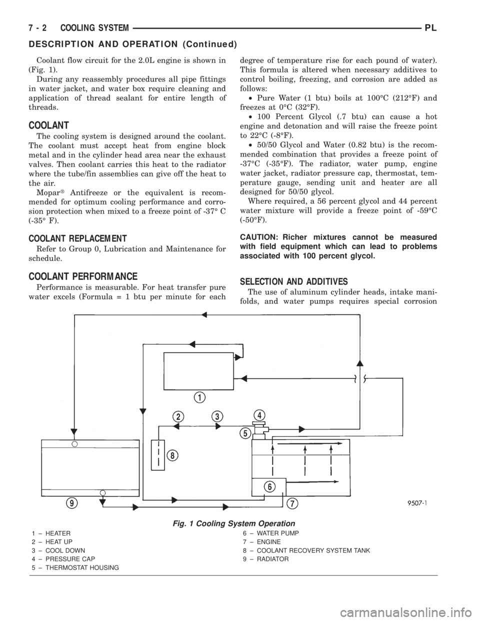
Coolant flow circuit for the 2.0L engine is shown in
(Fig. 1).
During any reassembly procedures all pipe fittings
in water jacket, and water box require cleaning and
application of thread sealant for entire length of
threads.
COOLANT
The cooling system is designed around the coolant.
The coolant must accept heat from engine block
metal and in the cylinder head area near the exhaust
valves. Then coolant carries this heat to the radiator
where the tube/fin assemblies can give off the heat to
the air.
MopartAntifreeze or the equivalent is recom-
mended for optimum cooling performance and corro-
sion protection when mixed to a freeze point of -37É C
(-35É F).
COOLANT REPLACEMENT
Refer to Group 0, Lubrication and Maintenance for
schedule.
COOLANT PERFORMANCE
Performance is measurable. For heat transfer pure
water excels (Formula = 1 btu per minute for eachdegree of temperature rise for each pound of water).
This formula is altered when necessary additives to
control boiling, freezing, and corrosion are added as
follows:
²Pure Water (1 btu) boils at 100ÉC (212ÉF) and
freezes at 0ÉC (32ÉF).
²100 Percent Glycol (.7 btu) can cause a hot
engine and detonation and will raise the freeze point
to 22ÉC (-8ÉF).
²50/50 Glycol and Water (0.82 btu) is the recom-
mended combination that provides a freeze point of
-37ÉC (-35ÉF). The radiator, water pump, engine
water jacket, radiator pressure cap, thermostat, tem-
perature gauge, sending unit and heater are all
designed for 50/50 glycol.
Where required, a 56 percent glycol and 44 percent
water mixture will provide a freeze point of -59ÉC
(-50ÉF).
CAUTION: Richer mixtures cannot be measured
with field equipment which can lead to problems
associated with 100 percent glycol.SELECTION AND ADDITIVES
The use of aluminum cylinder heads, intake mani-
folds, and water pumps requires special corrosion
Fig. 1 Cooling System Operation
1 ± HEATER
2 ± HEAT UP
3 ± COOL DOWN
4 ± PRESSURE CAP
5 ± THERMOSTAT HOUSING6 ± WATER PUMP
7 ± ENGINE
8 ± COOLANT RECOVERY SYSTEM TANK
9 ± RADIATOR
7 - 2 COOLING SYSTEMPL
DESCRIPTION AND OPERATION (Continued)
Page 800 of 1285
catalytic converter. Failure of the catalytic converter
can occur due to temperature increases caused by
unburned fuel passing through the converter. This
deterioration of the catalyst core can result in exces-
sively high emission levels, noise complaints, and
exhaust restrictions.
The use of catalysts also involves some non-auto-
motive problems. Unleaded gasoline must be used to
avoid poisoning the catalyst core. Do not allow engine
to operate above 1200 RPM in neutral for extended
periods over 5 minutes. This condition may result in
excessive exhaust system/floor pan temperatures
because of no air movement under the vehicle.
There is no regularly scheduled maintenance on
any DaimlerChrysler catalytic converter. If damaged,
the converter must be replaced.
CAUTION: Due to exterior physical similarities of
some catalytic converters with pipe assemblies,
extreme care should be taken with replacement
parts.
EXHAUST HEAT SHIELDS
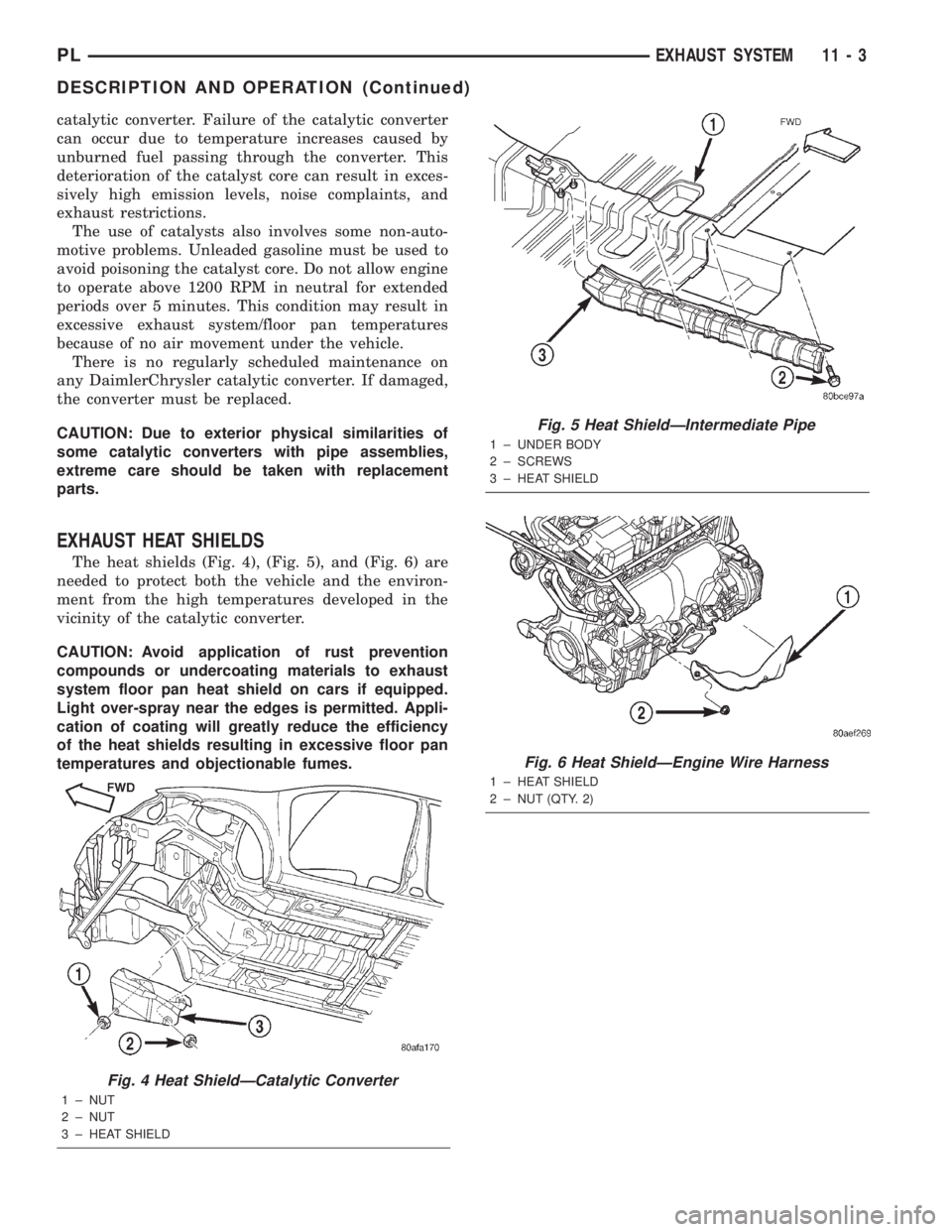
The heat shields (Fig. 4), (Fig. 5), and (Fig. 6) are
needed to protect both the vehicle and the environ-
ment from the high temperatures developed in the
vicinity of the catalytic converter.
CAUTION: Avoid application of rust prevention
compounds or undercoating materials to exhaust
system floor pan heat shield on cars if equipped.
Light over-spray near the edges is permitted. Appli-
cation of coating will greatly reduce the efficiency
of the heat shields resulting in excessive floor pan
temperatures and objectionable fumes.
Fig. 4 Heat ShieldÐCatalytic Converter
1 ± NUT
2 ± NUT
3 ± HEAT SHIELD
Fig. 5 Heat ShieldÐIntermediate Pipe
1 ± UNDER BODY
2 ± SCREWS
3 ± HEAT SHIELD
Fig. 6 Heat ShieldÐEngine Wire Harness
1 ± HEAT SHIELD
2 ± NUT (QTY. 2)
PLEXHAUST SYSTEM 11 - 3
DESCRIPTION AND OPERATION (Continued)