maintenance DODGE NEON 2000 Service Service Manual
[x] Cancel search | Manufacturer: DODGE, Model Year: 2000, Model line: NEON, Model: DODGE NEON 2000Pages: 1285, PDF Size: 29.42 MB
Page 160 of 1285
(14) Refer to DISASSEMBLY AND ASSEMBLY in
this section of this group for the procedure on sepa-
rating and reattaching the CAB to the HCU.
INSTALLATION
(1) Install the ICU onto its mounting bracket.
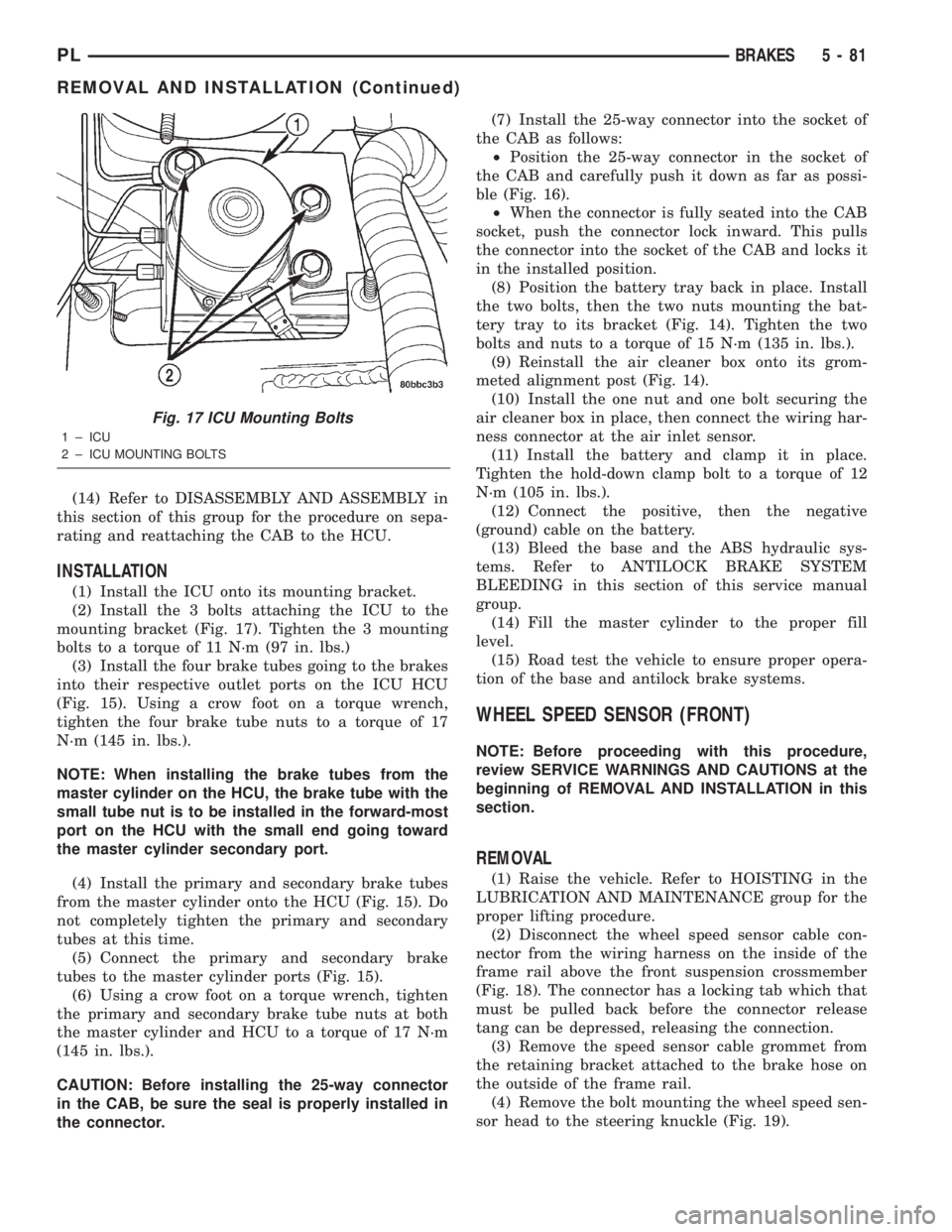
(2) Install the 3 bolts attaching the ICU to the
mounting bracket (Fig. 17). Tighten the 3 mounting
bolts to a torque of 11 N´m (97 in. lbs.)
(3) Install the four brake tubes going to the brakes
into their respective outlet ports on the ICU HCU
(Fig. 15). Using a crow foot on a torque wrench,
tighten the four brake tube nuts to a torque of 17
N´m (145 in. lbs.).
NOTE: When installing the brake tubes from the
master cylinder on the HCU, the brake tube with the
small tube nut is to be installed in the forward-most
port on the HCU with the small end going toward
the master cylinder secondary port.
(4) Install the primary and secondary brake tubes
from the master cylinder onto the HCU (Fig. 15). Do
not completely tighten the primary and secondary
tubes at this time.
(5) Connect the primary and secondary brake
tubes to the master cylinder ports (Fig. 15).
(6) Using a crow foot on a torque wrench, tighten
the primary and secondary brake tube nuts at both
the master cylinder and HCU to a torque of 17 N´m
(145 in. lbs.).
CAUTION: Before installing the 25-way connector
in the CAB, be sure the seal is properly installed in
the connector.(7) Install the 25-way connector into the socket of
the CAB as follows:
²Position the 25-way connector in the socket of
the CAB and carefully push it down as far as possi-
ble (Fig. 16).
²When the connector is fully seated into the CAB
socket, push the connector lock inward. This pulls
the connector into the socket of the CAB and locks it
in the installed position.
(8) Position the battery tray back in place. Install
the two bolts, then the two nuts mounting the bat-
tery tray to its bracket (Fig. 14). Tighten the two
bolts and nuts to a torque of 15 N´m (135 in. lbs.).
(9) Reinstall the air cleaner box onto its grom-
meted alignment post (Fig. 14).
(10) Install the one nut and one bolt securing the
air cleaner box in place, then connect the wiring har-
ness connector at the air inlet sensor.
(11) Install the battery and clamp it in place.
Tighten the hold-down clamp bolt to a torque of 12
N´m (105 in. lbs.).
(12) Connect the positive, then the negative
(ground) cable on the battery.
(13) Bleed the base and the ABS hydraulic sys-
tems. Refer to ANTILOCK BRAKE SYSTEM
BLEEDING in this section of this service manual
group.
(14) Fill the master cylinder to the proper fill
level.
(15) Road test the vehicle to ensure proper opera-
tion of the base and antilock brake systems.
WHEEL SPEED SENSOR (FRONT)
NOTE: Before proceeding with this procedure,
review SERVICE WARNINGS AND CAUTIONS at the
beginning of REMOVAL AND INSTALLATION in this
section.
REMOVAL
(1) Raise the vehicle. Refer to HOISTING in the
LUBRICATION AND MAINTENANCE group for the
proper lifting procedure.
(2) Disconnect the wheel speed sensor cable con-
nector from the wiring harness on the inside of the
frame rail above the front suspension crossmember
(Fig. 18). The connector has a locking tab which that
must be pulled back before the connector release
tang can be depressed, releasing the connection.
(3) Remove the speed sensor cable grommet from
the retaining bracket attached to the brake hose on
the outside of the frame rail.
(4) Remove the bolt mounting the wheel speed sen-
sor head to the steering knuckle (Fig. 19).
Fig. 17 ICU Mounting Bolts
1 ± ICU
2 ± ICU MOUNTING BOLTS
PLBRAKES 5 - 81
REMOVAL AND INSTALLATION (Continued)
Page 162 of 1285
WHEEL SPEED SENSOR (REAR)
NOTE: Before proceeding with this procedure,
review SERVICE WARNINGS AND CAUTIONS at the
beginning of REMOVAL AND INSTALLATION in this
section.
REMOVAL
(1) Raise the vehicle. Refer to HOISTING in the
LUBRICATION AND MAINTENANCE group for the
proper lifting procedure.
(2) Remove the tire and wheel assembly from the
vehicle.
(3) Disconnect the wheel speed sensor cable con-
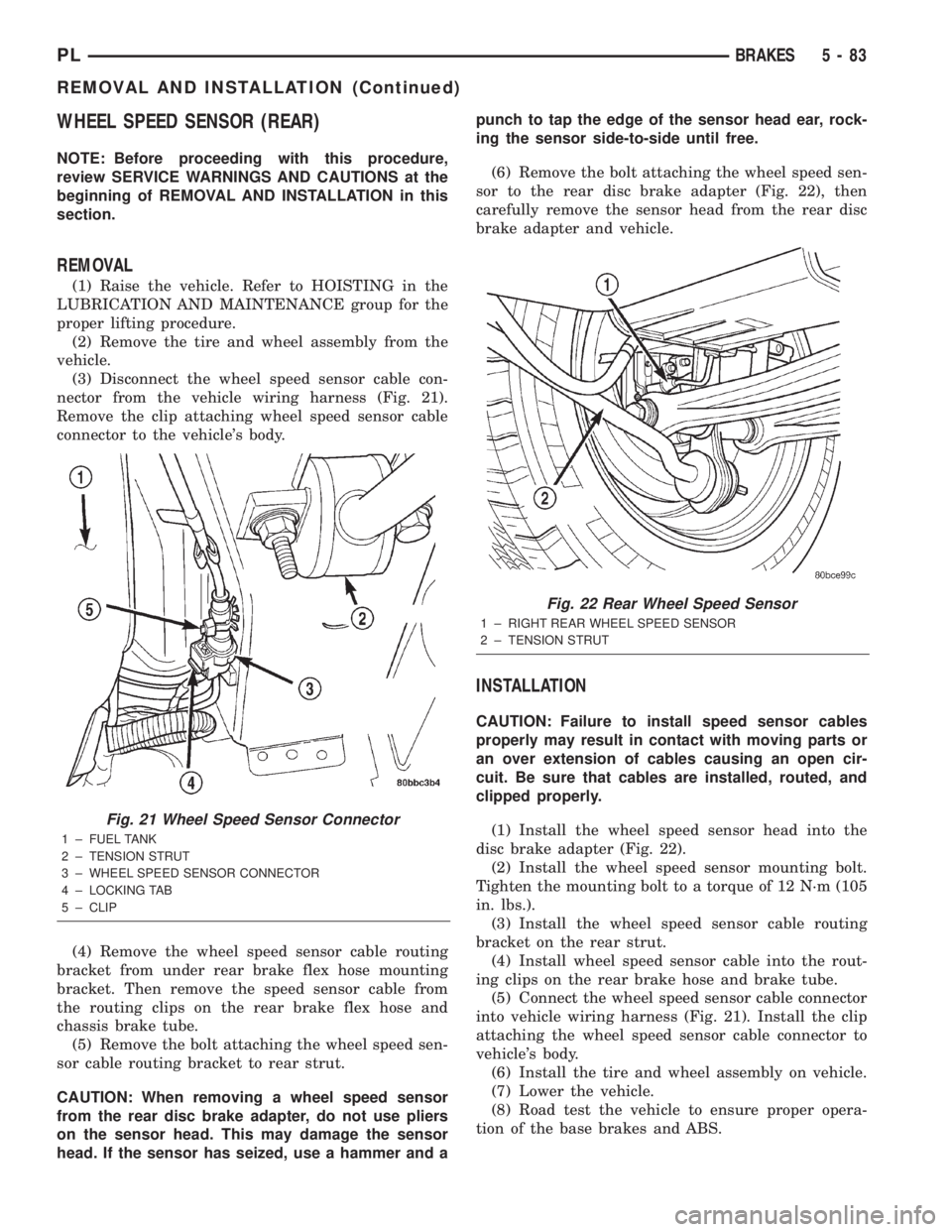
nector from the vehicle wiring harness (Fig. 21).
Remove the clip attaching wheel speed sensor cable
connector to the vehicle's body.
(4) Remove the wheel speed sensor cable routing
bracket from under rear brake flex hose mounting
bracket. Then remove the speed sensor cable from
the routing clips on the rear brake flex hose and
chassis brake tube.
(5) Remove the bolt attaching the wheel speed sen-
sor cable routing bracket to rear strut.
CAUTION: When removing a wheel speed sensor
from the rear disc brake adapter, do not use pliers
on the sensor head. This may damage the sensor
head. If the sensor has seized, use a hammer and apunch to tap the edge of the sensor head ear, rock-
ing the sensor side-to-side until free.
(6) Remove the bolt attaching the wheel speed sen-
sor to the rear disc brake adapter (Fig. 22), then
carefully remove the sensor head from the rear disc
brake adapter and vehicle.
INSTALLATION
CAUTION: Failure to install speed sensor cables
properly may result in contact with moving parts or
an over extension of cables causing an open cir-
cuit. Be sure that cables are installed, routed, and
clipped properly.
(1) Install the wheel speed sensor head into the
disc brake adapter (Fig. 22).
(2) Install the wheel speed sensor mounting bolt.
Tighten the mounting bolt to a torque of 12 N´m (105
in. lbs.).
(3) Install the wheel speed sensor cable routing
bracket on the rear strut.
(4) Install wheel speed sensor cable into the rout-
ing clips on the rear brake hose and brake tube.
(5) Connect the wheel speed sensor cable connector
into vehicle wiring harness (Fig. 21). Install the clip
attaching the wheel speed sensor cable connector to
vehicle's body.
(6) Install the tire and wheel assembly on vehicle.
(7) Lower the vehicle.
(8) Road test the vehicle to ensure proper opera-
tion of the base brakes and ABS.
Fig. 21 Wheel Speed Sensor Connector
1 ± FUEL TANK
2 ± TENSION STRUT
3 ± WHEEL SPEED SENSOR CONNECTOR
4 ± LOCKING TAB
5 ± CLIP
Fig. 22 Rear Wheel Speed Sensor
1 ± RIGHT REAR WHEEL SPEED SENSOR
2 ± TENSION STRUT
PLBRAKES 5 - 83
REMOVAL AND INSTALLATION (Continued)
Page 181 of 1285
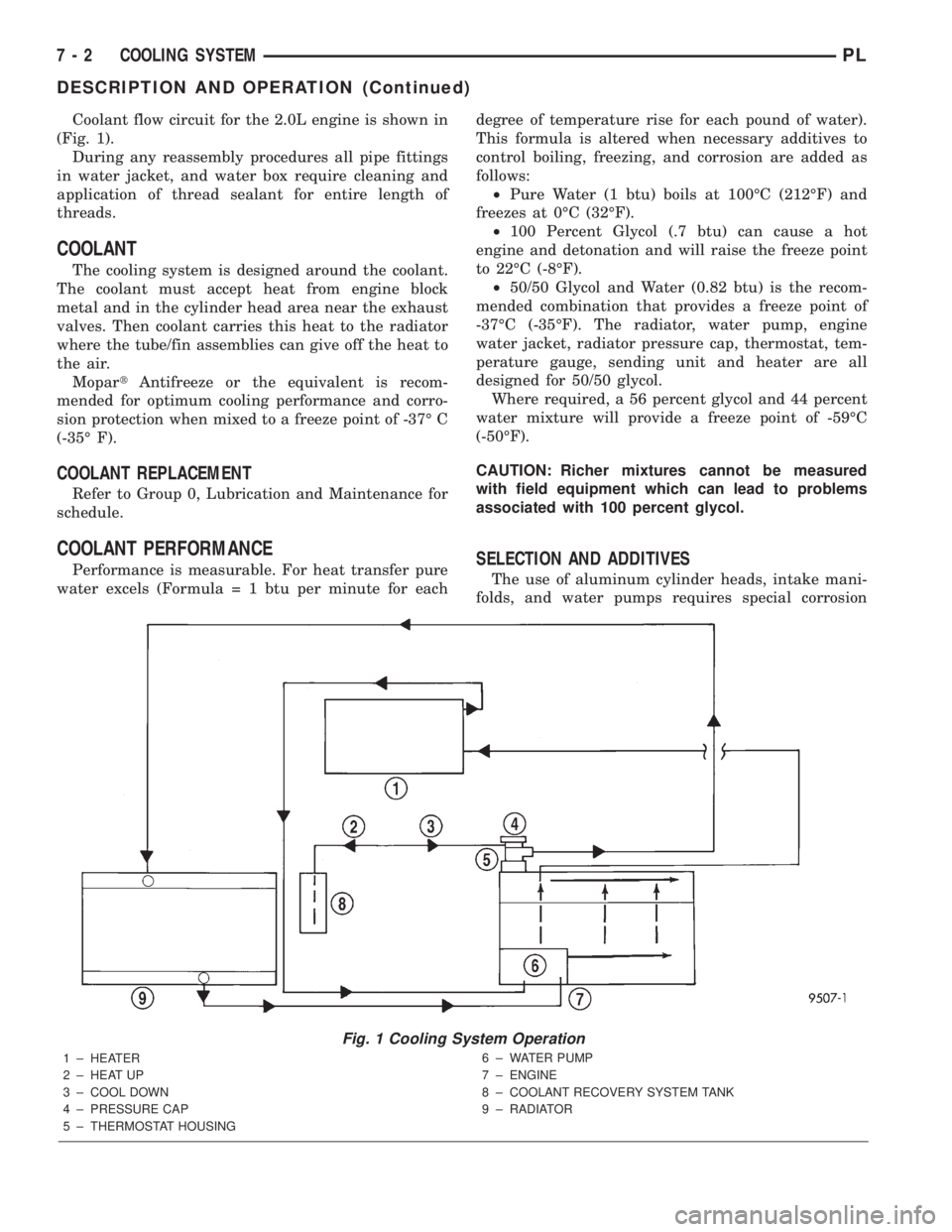
Coolant flow circuit for the 2.0L engine is shown in
(Fig. 1).
During any reassembly procedures all pipe fittings
in water jacket, and water box require cleaning and
application of thread sealant for entire length of
threads.
COOLANT
The cooling system is designed around the coolant.
The coolant must accept heat from engine block
metal and in the cylinder head area near the exhaust
valves. Then coolant carries this heat to the radiator
where the tube/fin assemblies can give off the heat to
the air.
MopartAntifreeze or the equivalent is recom-
mended for optimum cooling performance and corro-
sion protection when mixed to a freeze point of -37É C
(-35É F).
COOLANT REPLACEMENT
Refer to Group 0, Lubrication and Maintenance for
schedule.
COOLANT PERFORMANCE
Performance is measurable. For heat transfer pure
water excels (Formula = 1 btu per minute for eachdegree of temperature rise for each pound of water).
This formula is altered when necessary additives to
control boiling, freezing, and corrosion are added as
follows:
²Pure Water (1 btu) boils at 100ÉC (212ÉF) and
freezes at 0ÉC (32ÉF).
²100 Percent Glycol (.7 btu) can cause a hot
engine and detonation and will raise the freeze point
to 22ÉC (-8ÉF).
²50/50 Glycol and Water (0.82 btu) is the recom-
mended combination that provides a freeze point of
-37ÉC (-35ÉF). The radiator, water pump, engine
water jacket, radiator pressure cap, thermostat, tem-
perature gauge, sending unit and heater are all
designed for 50/50 glycol.
Where required, a 56 percent glycol and 44 percent
water mixture will provide a freeze point of -59ÉC
(-50ÉF).
CAUTION: Richer mixtures cannot be measured
with field equipment which can lead to problems
associated with 100 percent glycol.SELECTION AND ADDITIVES
The use of aluminum cylinder heads, intake mani-
folds, and water pumps requires special corrosion
Fig. 1 Cooling System Operation
1 ± HEATER
2 ± HEAT UP
3 ± COOL DOWN
4 ± PRESSURE CAP
5 ± THERMOSTAT HOUSING6 ± WATER PUMP
7 ± ENGINE
8 ± COOLANT RECOVERY SYSTEM TANK
9 ± RADIATOR
7 - 2 COOLING SYSTEMPL
DESCRIPTION AND OPERATION (Continued)
Page 198 of 1285
COOLING SYSTEMÐDRAINING
NOTE: Drain, flush, and fill the cooling system at
the mileage or time intervals specified in Group 0,
Lubrication and Maintenance. If the solution is dirty,
rusty, or contains a considerable amount of sedi-
ment; clean and flush with a reliable cooling system
cleaner. Care should be taken in disposing of the
used engine coolant from your vehicle. Check gov-
ernmental regulations for disposal of used engine
coolant.
Without removing radiator pressure cap and
with system not under pressure:
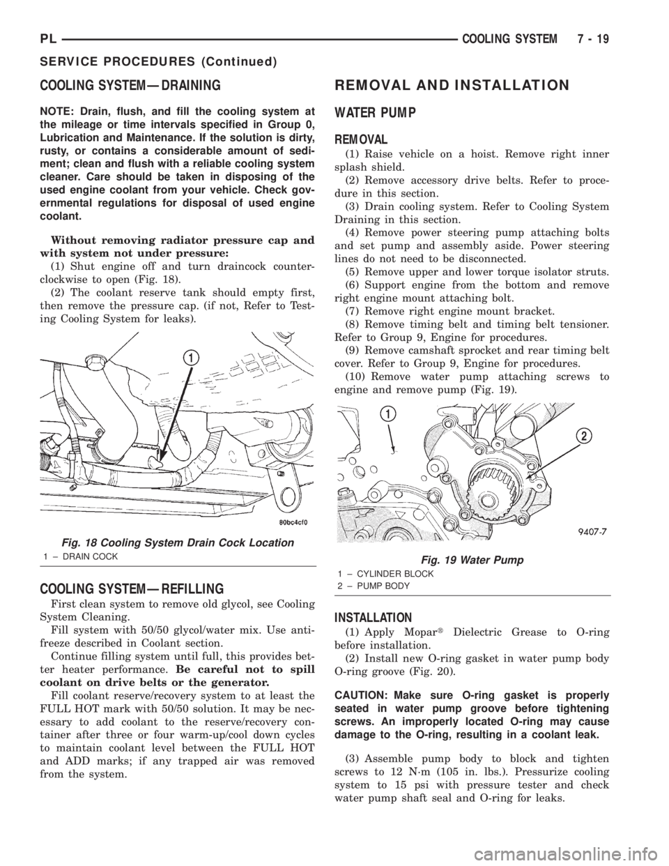
(1) Shut engine off and turn draincock counter-
clockwise to open (Fig. 18).
(2) The coolant reserve tank should empty first,
then remove the pressure cap. (if not, Refer to Test-
ing Cooling System for leaks).
COOLING SYSTEMÐREFILLING
First clean system to remove old glycol, see Cooling
System Cleaning.
Fill system with 50/50 glycol/water mix. Use anti-
freeze described in Coolant section.
Continue filling system until full, this provides bet-
ter heater performance.Be careful not to spill
coolant on drive belts or the generator.
Fill coolant reserve/recovery system to at least the
FULL HOT mark with 50/50 solution. It may be nec-
essary to add coolant to the reserve/recovery con-
tainer after three or four warm-up/cool down cycles
to maintain coolant level between the FULL HOT
and ADD marks; if any trapped air was removed
from the system.
REMOVAL AND INSTALLATION
WATER PUMP
REMOVAL
(1) Raise vehicle on a hoist. Remove right inner
splash shield.
(2) Remove accessory drive belts. Refer to proce-
dure in this section.
(3) Drain cooling system. Refer to Cooling System
Draining in this section.
(4) Remove power steering pump attaching bolts
and set pump and assembly aside. Power steering
lines do not need to be disconnected.
(5) Remove upper and lower torque isolator struts.
(6) Support engine from the bottom and remove
right engine mount attaching bolt.
(7) Remove right engine mount bracket.
(8) Remove timing belt and timing belt tensioner.
Refer to Group 9, Engine for procedures.
(9) Remove camshaft sprocket and rear timing belt
cover. Refer to Group 9, Engine for procedures.
(10) Remove water pump attaching screws to
engine and remove pump (Fig. 19).
INSTALLATION
(1) Apply MopartDielectric Grease to O-ring
before installation.
(2) Install new O-ring gasket in water pump body
O-ring groove (Fig. 20).
CAUTION: Make sure O-ring gasket is properly
seated in water pump groove before tightening
screws. An improperly located O-ring may cause
damage to the O-ring, resulting in a coolant leak.
(3) Assemble pump body to block and tighten
screws to 12 N´m (105 in. lbs.). Pressurize cooling
system to 15 psi with pressure tester and check
water pump shaft seal and O-ring for leaks.
Fig. 18 Cooling System Drain Cock Location
1 ± DRAIN COCKFig. 19 Water Pump
1 ± CYLINDER BLOCK
2 ± PUMP BODY
PLCOOLING SYSTEM 7 - 19
SERVICE PROCEDURES (Continued)
Page 210 of 1285
BATTERY
TABLE OF CONTENTS
page page
GENERAL INFORMATION
INTRODUCTION..........................1
DESCRIPTION AND OPERATION
BATTERY IGNITION OFF DRAW (IOD).........2
CHARGING TIME REQUIRED................2
DIAGNOSIS AND TESTING
BATTERY BUILT-IN TEST INDICATOR.........3
BATTERY IGNITION OFF DRAW (IOD).........4
BATTERY LOAD TEST......................6
BATTERY OPEN CIRCUIT VOLTAGE...........7
SERVICE PROCEDURES
BATTERY CHARGING......................7CHARGING COMPLETELY DISCHARGED
BATTERY..............................8
VISUAL INSPECTION......................9
REMOVAL AND INSTALLATION
BATTERY...............................10
BATTERY THERMOWRAP..................10
BATTERY TRAY..........................11
SPECIFICATIONS
BATTERY SPECIFICATIONS................11
TORQUE...............................11
GENERAL INFORMATION
INTRODUCTION
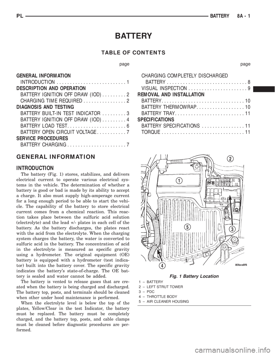
The battery (Fig. 1) stores, stabilizes, and delivers
electrical current to operate various electrical sys-
tems in the vehicle. The determination of whether a
battery is good or bad is made by its ability to accept
a charge. It also must supply high-amperage current
for a long enough period to be able to start the vehi-
cle. The capability of the battery to store electrical
current comes from a chemical reaction. This reac-
tion takes place between the sulfuric acid solution
(electrolyte) and the lead +/- plates in each cell of the
battery. As the battery discharges, the plates react
with the acid from the electrolyte. When the charging
system charges the battery, the water is converted to
sulfuric acid in the battery. The concentration of acid
in the electrolyte is measured as specific gravity
using a hydrometer. The original equipment (OE)
battery is equipped with a hydrometer (test indica-
tor) built into the battery cover. The specific gravity
indicates the battery's state-of-charge. The OE bat-
tery is sealed and water cannot be added.
The battery is vented to release gases that are cre-
ated when the battery is being charged and discharged.
The battery top, posts, and terminals should be cleaned
when other under hood maintenance is performed.
When the electrolyte level is below the top of the
plates, Yellow/Clear in the test Indicator, the battery
must be replaced. The battery must be completely
charged, and the battery top, posts, and cable clamps
must be cleaned before diagnostic procedures are per-
formed.
Fig. 1 Battery Location
1 ± BATTERY
2 ± LEFT STRUT TOWER
3 ± PDC
4 ± THROTTLE BODY
5 ± AIR CLEANER HOUSING
PLBATTERY 8A - 1
Page 212 of 1285
DIAGNOSIS AND TESTING
BATTERY BUILT-IN TEST INDICATOR
USING TEST INDICATOR
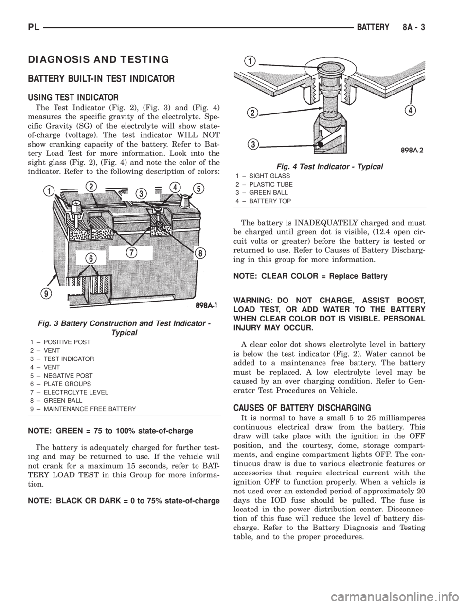
The Test Indicator (Fig. 2), (Fig. 3) and (Fig. 4)
measures the specific gravity of the electrolyte. Spe-
cific Gravity (SG) of the electrolyte will show state-
of-charge (voltage). The test indicator WILL NOT
show cranking capacity of the battery. Refer to Bat-
tery Load Test for more information. Look into the
sight glass (Fig. 2), (Fig. 4) and note the color of the
indicator. Refer to the following description of colors:
NOTE: GREEN = 75 to 100% state-of-charge
The battery is adequately charged for further test-
ing and may be returned to use. If the vehicle will
not crank for a maximum 15 seconds, refer to BAT-
TERY LOAD TEST in this Group for more informa-
tion.
NOTE: BLACK OR DARK=0to75%state-of-chargeThe battery is INADEQUATELY charged and must
be charged until green dot is visible, (12.4 open cir-
cuit volts or greater) before the battery is tested or
returned to use. Refer to Causes of Battery Discharg-
ing in this group for more information.
NOTE: CLEAR COLOR = Replace Battery
WARNING: DO NOT CHARGE, ASSIST BOOST,
LOAD TEST, OR ADD WATER TO THE BATTERY
WHEN CLEAR COLOR DOT IS VISIBLE. PERSONAL
INJURY MAY OCCUR.
A clear color dot shows electrolyte level in battery
is below the test indicator (Fig. 2). Water cannot be
added to a maintenance free battery. The battery
must be replaced. A low electrolyte level may be
caused by an over charging condition. Refer to Gen-
erator Test Procedures on Vehicle.
CAUSES OF BATTERY DISCHARGING
It is normal to have a small 5 to 25 milliamperes
continuous electrical draw from the battery. This
draw will take place with the ignition in the OFF
position, and the courtesy, dome, storage compart-
ments, and engine compartment lights OFF. The con-
tinuous draw is due to various electronic features or
accessories that require electrical current with the
ignition OFF to function properly. When a vehicle is
not used over an extended period of approximately 20
days the IOD fuse should be pulled. The fuse is
located in the power distribution center. Disconnec-
tion of this fuse will reduce the level of battery dis-
charge. Refer to the Battery Diagnosis and Testing
table, and to the proper procedures.
Fig. 3 Battery Construction and Test Indicator -
Typical
1 ± POSITIVE POST
2 ± VENT
3 ± TEST INDICATOR
4 ± VENT
5 ± NEGATIVE POST
6 ± PLATE GROUPS
7 ± ELECTROLYTE LEVEL
8 ± GREEN BALL
9 ± MAINTENANCE FREE BATTERY
Fig. 4 Test Indicator - Typical
1 ± SIGHT GLASS
2 ± PLASTIC TUBE
3 ± GREEN BALL
4 ± BATTERY TOP
PLBATTERY 8A - 3
Page 346 of 1285
PASSIVE RESTRAINT SYSTEMS
TABLE OF CONTENTS
page page
GENERAL INFORMATION
WARNINGS AND PRECAUTIONS.............1
DESCRIPTION AND OPERATION
AIRBAG CONTROL MODULE (ACM)..........1
CLOCKSPRING...........................2
DRIVER and PASSENGER AIRBAG MODULE....2
DIAGNOSIS AND TESTING
AIRBAG SYSTEM.........................3
SERVICE PROCEDURES
CLEAN UP PROCEDURE....................3HANDLING AIRBAG MODULES..............4
MAINTENANCE INSPECTION................4
REMOVAL AND INSTALLATION
AIRBAG CONTROL MODULE (ACM)..........4
CLOCKSPRING...........................5
DRIVER AIRBAG MODULE..................6
PASSENGER AIRBAG MODULE..............7
STEERING WHEEL........................8
ADJUSTMENTS
CLOCKSPRING CENTERING PROCEDURE......9
GENERAL INFORMATION
WARNINGS AND PRECAUTIONS
WARNING: THIS SYSTEM IS A SENSITIVE, COM-
PLEX ELECTRO±MECHANICAL UNIT. DISCONNECT
AND ISOLATE THE BATTERY NEGATIVE CABLE
BEFORE BEGINNING AIRBAG SYSTEM COMPO-
NENT REMOVAL OR INSTALLATION PROCEDURES.
THIS WILL DISABLE THE AIRBAG SYSTEM. FAIL-
URE TO DISCONNECT THE BATTERY COULD
RESULT IN ACCIDENTAL AIRBAG DEPLOYMENT
AND POSSIBLE PERSONAL INJURY.
ALLOW SYSTEM CAPACITOR TO DISCHARGE
FOR ONE MINUTE BEFORE REMOVING AIRBAG
COMPONENTS.
DO NOT PLACE AN INTACT UNDEPLOYED AIRBAG
FACE DOWN ON A SOLID SURFACE, THE AIRBAG
WILL PROPEL INTO THE AIR IF ACCIDENTALLY
DEPLOYED AND COULD RESULT IN PERSONAL
INJURY. WHEN CARRYING OR HANDLING AN UNDE-
PLOYED AIRBAG MODULE, THE TRIM SIDE OF THE
AIRBAG SHOULD BE POINTING AWAY FROM THE
BODY TO MINIMIZE POSSIBILITY OF INJURY IF ACCI-
DENTAL DEPLOYMENT OCCURS.
REPLACE AIRBAG SYSTEM COMPONENTS WITH
MOPARTREPLACEMENT PARTS. SUBSTITUTE
PARTS MAY APPEAR INTERCHANGEABLE, BUT
INTERNAL DIFFERENCES MAY RESULT IN INFE-
RIOR OCCUPANT PROTECTION.
WEAR SAFETY GLASSES, RUBBER GLOVES,
AND LONG SLEEVES CLOTHING WHEN CLEANING
POWDER RESIDUE FROM VEHICLE AFTER AIRBAG
DEPLOYMENT. SODIUM HYDROXIDE POWDER
RESIDUE EMITTED FROM A DEPLOYED AIRBAG
CAN CAUSE SKIN IRRITATION. FLUSH AFFECTEDAREA WITH COOL WATER IF IRRITATION IS EXPE-
RIENCED. IF NASAL OR THROAT IRRITATION IS
EXPERIENCED, EXIT THE VEHICLE FOR FRESH AIR
UNTIL THE IRRITATION CEASES. IF IRRITATION
CONTINUES, SEE A PHYSICIAN.
DO NOT USE A REPLACEMENT AIRBAG THAT IS
NOT IN THE ORIGINAL PACKAGING, IMPROPER
DEPLOYMENT AND PERSONAL INJURY CAN
RESULT.
THE FACTORY INSTALLED FASTENERS,
SCREWS AND BOLTS USED TO FASTEN AIRBAG
COMPONENTS HAVE A SPECIAL COATING AND
ARE SPECIFICALLY DESIGNED FOR THE AIRBAG
SYSTEM. DO NOT USE SUBSTITUTE FASTENERS,
USE ONLY ORIGINAL EQUIPMENT FASTENERS
LISTED IN THE PARTS CATALOG WHEN FASTENER
REPLACEMENT IS REQUIRED.
NOTE: Airbags should be stored in a cool dry loca-
tion away from excessive heat and static electrical
activity with the fabric airbag facing UP, or a prema-
ture deployment can result.
If the Driver/Passenger Airbag Module is defective
and not deployed, refer to DaimlerChrysler Corpora-
tion current return list for proper handling proce-
dures.
DESCRIPTION AND OPERATION
AIRBAG CONTROL MODULE (ACM)
The Airbag Control Module (ACM) contains the
sensing element, safing sensor, and energy reserve
capacitor. The module is mounted on the tunnel/floor
pan between the gear shift lever and the park brake
PLPASSIVE RESTRAINT SYSTEMS 8M - 1
Page 349 of 1285
²Clockspring assembly
²Steering Column Assembly w/Lower Steering
Column Coupler
PASSENGER AIRBAG
After a Passenger Airbag Module has been
deployed, replace the following components because
they cannot be reused.
²Passenger Airbag Module
Inspect all the attaching hardware and instrument
panel for damage. If damage is evident, components
should be replaced.
HANDLING AIRBAG MODULES
DEPLOYED AIRBAG MODULE
The vehicle interior may contain a very small
amount of sodium hydroxide powder, a by-product of
airbag deployment. Sodium hydroxide powder can
irritate the skin, eyes, nose and throat. Wear safety
glasses, rubber gloves, and long sleeved clothing
when cleaning any of the powder residue from the
vehicle.
If you find that the cleanup is irritating your skin,
run cool water over the affected area. Also, if you
experience nasal or throat irritation, exit the vehicle
for fresh air until the irritation ceases. If irritation
continues, see a physician.
UNDEPLOYED AIRBAG MODULE
The airbag modules must be stored in its original
special container until used for service. At no time
should a source of electricity be permitted near the
inflator on the back of an airbag module. When car-
rying or handling an undeployed airbag module, the
trim side of the airbag should be pointing away from
the body to minimize possibility of injury if acciden-
tal deployment occurs. Do not place undeployed air-
bag face down on a solid surface, the airbag will
propel into the air if accidentally deployment occurs.
MAINTENANCE INSPECTION
(1) Check the airbag warning lamp for proper
operation as follows:
(a) Turn ignition switch to the ON position, the
airbag warning lamp should light. If not, test the
system using a DRB llltscan tool and the proper
Body Diagnostic Procedures Manual.
(b) The airbag warning lamp lights, but fails to
go out after eight seconds. Test the system using a
DRB llltscan tool and the proper Body Diagnostic
Procedures Manual.
(c) After correcting active malfunction erase
stored Diagnostic Trouble Codes (DTC's).
REMOVAL AND INSTALLATION
AIRBAG CONTROL MODULE (ACM)
WARNING: THE ACM CONTAINS THE SENSING
ELEMENT AND A SAFING SENSOR WHICH
ENABLES THE SYSTEM TO DEPLOY THE AIR-
BAGS. TO AVOID ACCIDENTAL DEPLOYMENT,
NEVER CONNECT ACM ELECTRICALLY TO THE
SYSTEM WHILE VEHICLE BATTERY IS CON-
NECTED.
DISCONNECT AND ISOLATE THE BATTERY NEG-
ATIVE (GROUND) CABLE BEFORE BEGINNING ANY
AIRBAG SYSTEM COMPONENT REMOVAL OR
INSTALLATION PROCEDURE. THIS WILL DISABLE
THE AIRBAG SYSTEM. FAILURE TO DISCONNECT
BATTERY COULD RESULT IN ACCIDENTAL AIRBAG
DEPLOYMENT AND POSSIBLE PERSONAL INJURY.
ALLOW SYSTEM CAPACITOR TO DISCHARGE
FOR 1 MINUTE BEFORE REMOVING ANY AIRBAG
COMPONENTS.
REMOVAL
(1) Disconnect and isolate the battery negative
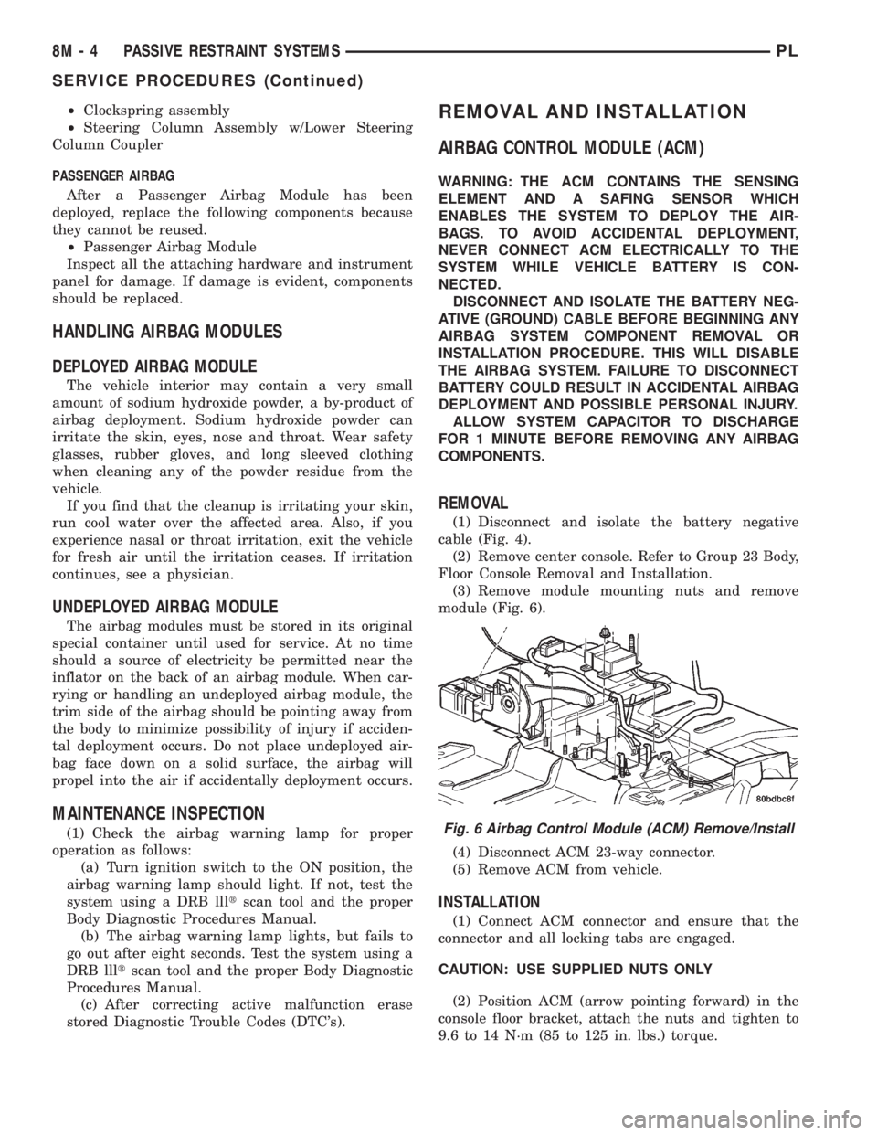
cable (Fig. 4).
(2) Remove center console. Refer to Group 23 Body,
Floor Console Removal and Installation.
(3) Remove module mounting nuts and remove
module (Fig. 6).
(4) Disconnect ACM 23-way connector.
(5) Remove ACM from vehicle.
INSTALLATION
(1) Connect ACM connector and ensure that the
connector and all locking tabs are engaged.
CAUTION: USE SUPPLIED NUTS ONLY
(2) Position ACM (arrow pointing forward) in the
console floor bracket, attach the nuts and tighten to
9.6 to 14 N´m (85 to 125 in. lbs.) torque.
Fig. 6 Airbag Control Module (ACM) Remove/Install
8M - 4 PASSIVE RESTRAINT SYSTEMSPL
SERVICE PROCEDURES (Continued)
Page 726 of 1285
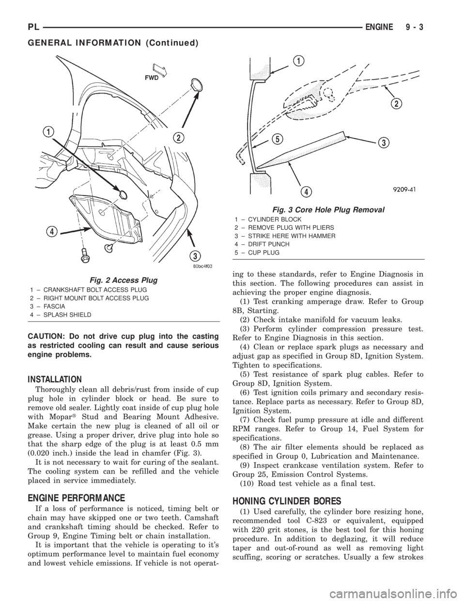
CAUTION: Do not drive cup plug into the casting
as restricted cooling can result and cause serious
engine problems.
INSTALLATION
Thoroughly clean all debris/rust from inside of cup
plug hole in cylinder block or head. Be sure to
remove old sealer. Lightly coat inside of cup plug hole
with MopartStud and Bearing Mount Adhesive.
Make certain the new plug is cleaned of all oil or
grease. Using a proper driver, drive plug into hole so
that the sharp edge of the plug is at least 0.5 mm
(0.020 inch.) inside the lead in chamfer (Fig. 3).
It is not necessary to wait for curing of the sealant.
The cooling system can be refilled and the vehicle
placed in service immediately.
ENGINE PERFORMANCE
If a loss of performance is noticed, timing belt or
chain may have skipped one or two teeth. Camshaft
and crankshaft timing should be checked. Refer to
Group 9, Engine Timing belt or chain installation.
It is important that the vehicle is operating to it's
optimum performance level to maintain fuel economy
and lowest vehicle emissions. If vehicle is not operat-ing to these standards, refer to Engine Diagnosis in
this section. The following procedures can assist in
achieving the proper engine diagnosis.
(1) Test cranking amperage draw. Refer to Group
8B, Starting.
(2) Check intake manifold for vacuum leaks.
(3) Perform cylinder compression pressure test.
Refer to Engine Diagnosis in this section.
(4) Clean or replace spark plugs as necessary and
adjust gap as specified in Group 8D, Ignition System.
Tighten to specifications.
(5) Test resistance of spark plug cables. Refer to
Group 8D, Ignition System.
(6) Test ignition coils primary and secondary resis-
tance. Replace parts as necessary. Refer to Group 8D,
Ignition System.
(7) Check fuel pump pressure at idle and different
RPM ranges. Refer to Group 14, Fuel System for
specifications.
(8) The air filter elements should be replaced as
specified in Group 0, Lubrication and Maintenance.
(9) Inspect crankcase ventilation system. Refer to
Group 25, Emission Control Systems.
(10) Road test vehicle as a final test.HONING CYLINDER BORES
(1) Used carefully, the cylinder bore resizing hone,
recommended tool C-823 or equivalent, equipped
with 220 grit stones, is the best tool for this honing
procedure. In addition to deglazing, it will reduce
taper and out-of-round as well as removing light
scuffing, scoring or scratches. Usually a few strokes
Fig. 2 Access Plug
1 ± CRANKSHAFT BOLT ACCESS PLUG
2 ± RIGHT MOUNT BOLT ACCESS PLUG
3 ± FASCIA
4 ± SPLASH SHIELD
Fig. 3 Core Hole Plug Removal
1 ± CYLINDER BLOCK
2 ± REMOVE PLUG WITH PLIERS
3 ± STRIKE HERE WITH HAMMER
4 ± DRIFT PUNCH
5 ± CUP PLUG
PLENGINE 9 - 3
GENERAL INFORMATION (Continued)
Page 730 of 1285
ENGINE OIL SERVICE
WARNING: NEW OR USED ENGINE OIL CAN BE
IRRITATING TO THE SKIN. AVOID PROLONGED OR
REPEATED SKIN CONTACT WITH ENGINE OIL.
CONTAMINANTS IN USED ENGINE OIL, CAUSED BY
INTERNAL COMBUSTION, CAN BE HAZARDOUS TO
YOUR HEALTH. THOROUGHLY WASH EXPOSED
SKIN WITH SOAP AND WATER. DO NOT WASH
SKIN WITH GASOLINE, DIESEL FUEL, THINNER, OR
SOLVENTS, HEALTH PROBLEMS CAN RESULT. DO
NOT POLLUTE, DISPOSE OF USED ENGINE OIL
PROPERLY. CONTACT YOUR DEALER OR GOVERN-
MENT AGENCY FOR LOCATION OF COLLECTION
CENTER IN YOUR AREA.
ENGINE OIL SPECIFICATION
CAUTION: Do not use non-detergent or straight
mineral oil when adding or changing crankcase
lubricant. Engine failure can result.
API SERVICE GRADE CERTIFIED
Use an engine oil that is API Service Grade Certi-
fied. MOPARtprovides engine oils that conforms to
this service grade.
SAE VISCOSITY
An SAE viscosity grade is used to specify the vis-
cosity of engine oil. Use only, engine oils with multi-
ple viscosities such as 5W-30 or 10W-30. These are
specified with a dual SAE viscosity grade which indi-
cates the cold-to-hot temperature viscosity range.
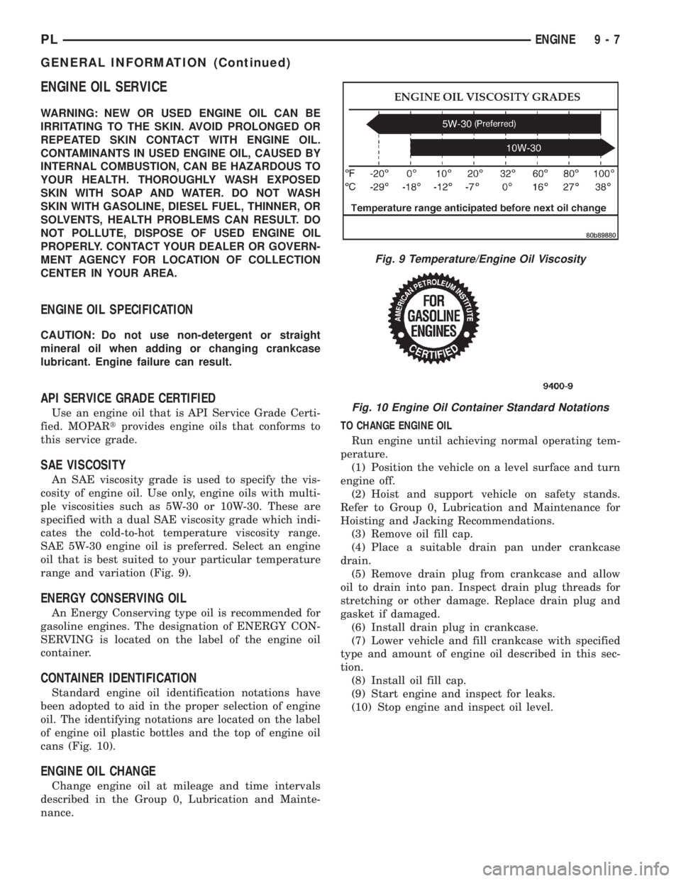
SAE 5W-30 engine oil is preferred. Select an engine
oil that is best suited to your particular temperature
range and variation (Fig. 9).
ENERGY CONSERVING OIL
An Energy Conserving type oil is recommended for
gasoline engines. The designation of ENERGY CON-
SERVING is located on the label of the engine oil
container.
CONTAINER IDENTIFICATION
Standard engine oil identification notations have
been adopted to aid in the proper selection of engine
oil. The identifying notations are located on the label
of engine oil plastic bottles and the top of engine oil
cans (Fig. 10).
ENGINE OIL CHANGE
Change engine oil at mileage and time intervals
described in the Group 0, Lubrication and Mainte-
nance.TO CHANGE ENGINE OIL
Run engine until achieving normal operating tem-
perature.
(1) Position the vehicle on a level surface and turn
engine off.
(2) Hoist and support vehicle on safety stands.
Refer to Group 0, Lubrication and Maintenance for
Hoisting and Jacking Recommendations.
(3) Remove oil fill cap.
(4) Place a suitable drain pan under crankcase
drain.
(5) Remove drain plug from crankcase and allow
oil to drain into pan. Inspect drain plug threads for
stretching or other damage. Replace drain plug and
gasket if damaged.
(6) Install drain plug in crankcase.
(7) Lower vehicle and fill crankcase with specified
type and amount of engine oil described in this sec-
tion.
(8) Install oil fill cap.
(9) Start engine and inspect for leaks.
(10) Stop engine and inspect oil level.
Fig. 9 Temperature/Engine Oil Viscosity
Fig. 10 Engine Oil Container Standard Notations
PLENGINE 9 - 7
GENERAL INFORMATION (Continued)