oil level DODGE NEON 2000 Service Service Manual
[x] Cancel search | Manufacturer: DODGE, Model Year: 2000, Model line: NEON, Model: DODGE NEON 2000Pages: 1285, PDF Size: 29.42 MB
Page 967 of 1285
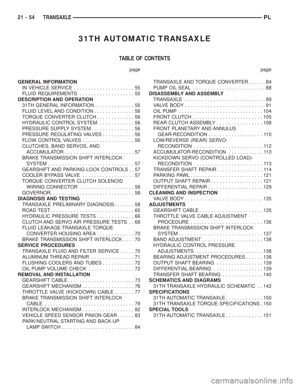
31TH AUTOMATIC TRANSAXLE
TABLE OF CONTENTS
page page
GENERAL INFORMATION
IN VEHICLE SERVICE.....................55
FLUID REQUIREMENTS...................55
DESCRIPTION AND OPERATION
31TH GENERAL INFORMATION..............55
FLUID LEVEL AND CONDITION..............56
TORQUE CONVERTER CLUTCH.............56
HYDRAULIC CONTROL SYSTEM.............56
PRESSURE SUPPLY SYSTEM...............56
PRESSURE REGULATING VALVES...........56
FLOW CONTROL VALVES..................56
CLUTCHES, BAND SERVOS, AND
ACCUMULATOR........................57
BRAKE TRANSMISSION SHIFT INTERLOCK
SYSTEM..............................57
GEARSHIFT AND PARKING LOCK CONTROLS . . 57
COOLER BYPASS VALVE..................57
TORQUE CONVERTER CLUTCH SOLENOID
WIRING CONNECTOR...................58
GOVERNOR.............................58
DIAGNOSIS AND TESTING
TRANSAXLE PRELIMINARY DIAGNOSIS.......58
ROAD TEST.............................65
HYDRAULIC PRESSURE TESTS.............66
CLUTCH AND SERVO AIR PRESSURE TESTS . . 68
FLUID LEAKAGE-TRANSAXLE TORQUE
CONVERTER HOUSING AREA.............70
BRAKE TRANSMISSION SHIFT INTERLOCK....70
SERVICE PROCEDURES
TRANSAXLE FLUID AND FILTER SERVICE.....70
ALUMINUM THREAD REPAIR...............71
FLUSHING COOLERS AND TUBES...........72
OIL PUMP VOLUME CHECK................72
REMOVAL AND INSTALLATION
GEARSHIFT CABLE.......................73
GEARSHIFT MECHANISM..................76
THROTTLE VALVE (KICKDOWN) CABLE.......77
BRAKE TRANSMISSION SHIFT INTERLOCK
CABLE...............................79
INTERLOCK MECHANISM..................82
VEHICLE SPEED SENSOR PINION GEAR......83
PARK/NEUTRAL STARTING AND BACK-UP
LAMP SWITCH.........................84TRANSAXLE AND TORQUE CONVERTER......84
PUMP OIL SEAL.........................88
DISASSEMBLY AND ASSEMBLY
TRANSAXLE............................89
VALVE BODY............................91
OIL PUMP.............................104
FRONT CLUTCH........................105
REAR CLUTCH ASSEMBLY................108
FRONT PLANETARY AND ANNULUS
GEAR-RECONDITION...................110
LOW/REVERSE (REAR) SERVO-
RECONDITION........................112
ACCUMULATOR-RECONDITION............113
KICKDOWN SERVO (CONTROLLED LOAD)-
RECONDITION........................113
TRANSFER SHAFT REPAIR................114
PARKING PAWL.........................121
OUTPUT SHAFT REPAIR..................121
DIFFERENTIAL REPAIR...................129
CLEANING AND INSPECTION
VALVE BODY...........................135
ADJUSTMENTS
GEARSHIFT CABLE......................135
THROTTLE VALVE CABLE ADJUSTMENT
PROCEDURE.........................136
BRAKE TRANSMISSION SHIFT INTERLOCK
SYSTEM.............................137
BAND ADJUSTMENT.....................138
HYDRAULIC CONTROL PRESSURE
ADJUSTMENTS.......................138
BEARING ADJUSTMENT PROCEDURES......138
OUTPUT SHAFT BEARING................139
DIFFERENTIAL BEARING.................139
TRANSFER SHAFT BEARING..............140
SCHEMATICS AND DIAGRAMS
31TH TRANSAXLE HYDRAULIC SCHEMATIC . . 142
SPECIFICATIONS
31TH AUTOMATIC TRANSAXLE.............150
31TH TRANSAXLE TORQUE SPECIFICATIONS . 150
SPECIAL TOOLS
31TH AUTOMATIC TRANSAXLE.............151
21 - 54 TRANSAXLEPL
Page 968 of 1285
GENERAL INFORMATION
IN VEHICLE SERVICE
The following components are serviceable in the
vehicle without transaxle removal:
²Valve Body Assembly
²Converter Clutch Solenoid
²Governor
²Vehicle Speed Sensor & Pinion
²Park/Neutral & Back-up Lamp Switch
²Transfer Gears and Transfer Shaft
²Low/Reverse Servo
²Kickdown Servo
²Accumulator
FLUID REQUIREMENTS
NOTE: The transmission and differential have a
common oil sump with an opening between the
two.
TRANSMISSION/DIFFERENTIAL
MopartATF+4 (Automatic Transmission Fluid
Type 9602) is required in this transaxle. Substitute
fluids must meet fluid specification MS-9602.
FLUID ADDITIVES
Chrysler Corporation strongly recommends against
the addition of any fluids to the transmission, other
than those automatic transmission fluids listed
above. Exceptions to this policy are the use of special
dyes to aid in detecting fluid leaks.
Various ªspecialº additives and supplements exist
that claim to improve shift feel/quality and converter
clutch operation, inhibit overheating, oxidation, var-
nish and sludge. These claims have not been sup-
ported to Chrysler's satisfaction and these additives
must not be used. The use of transmission ªsealersº
should also be avoided, since they may adversely
affect the integrity of tranmission seals.
DESCRIPTION AND OPERATION
31TH GENERAL INFORMATION
NOTE: Safety goggles should be worn at all times
when working on these transaxles.
This transaxle combines torque converter, three
speed transmission, final drive gearing, and differen-
tial into a front wheel drive system.
NOTE: Transaxle operation requirements are differ-
ent for each vehicle and engine combination. Some
internal parts will be different to provide for this.Therefore, when replacing parts, refer to the seven
digit part number stamped on rear of the transaxle
oil pan flange.
Within this transaxle, there are three primary
areas:
(1) Main center line plus valve body.
(2) Transfer shaft center line (includes governor
and parking sprag).
(3) Differential center line.
Center distances between the main rotating parts
in these three areas are held precise to maintain a
low noise level.
The torque converter, transaxle area, and differen-
tial are housed in an integral aluminum die casting.
The differential oil sump is common with the
transaxle sump. Separate filling of the differen-
tial is NOT necessary.
The torque converter is attached to the crankshaft
through a flexible driving plate. Cooling of the con-
verter is accomplished by circulating the transaxle
fluid through a remote cooler. There are two types of
coolers used. An oil-to-water type cooler located in
the radiator side tank and/or an oil-to-air heat
exchanger. The torque converter assembly is a sealed
unit that cannot be disassembled.
The transaxle fluid is filtered by an internal filter
attached to the lower side of the valve body assembly.
Engine torque is transmitted to the torque con-
verter and then through the input shaft to multiple-
disc clutches in the transaxle. The power flow
depends on the application of the clutches and bands.
Refer to Elements in Use Chart in Diagnosis and
Tests section.
The transaxle consists of:
²Two multiple-disc clutches
²An overrunning clutch
²Two servos
²A hydraulic accumulator
²Two bands
²Two planetary gear sets
This provides three forward ratios and a reverse
ratio. The common sun gear of the planetary gear
sets is connected to the front clutch by a driving
shell. The driving shell is splined to the sun gear and
front clutch retainer. The hydraulic system consists
of an oil pump and a single valve body which con-
tains all of the valves except the governor valves.
The transaxle sump and differential sump are both
vented through the dipstick. Output torque from the
main center line is delivered through helical gears to
the transfer shaft. This gear set is a factor in the
transaxle final drive (axle) ratio. The shaft also car-
ries the governor and parking sprag. An integral heli-
cal gear on the transfer shaft drives the differential
ring gear.
PLTRANSAXLE 21 - 55
Page 969 of 1285
FLUID LEVEL AND CONDITION
NOTE: The transmission and differential sump have
a common oil sump with a communicating opening
between the two.
The torque converter fills in both the P (Park) and
N (Neutral) positions. Place the selector lever in P
(Park) to be sure that the fluid level check is accu-
rate.The engine should be running at idle
speed for at least one minute, with the vehicle
on level ground. This will ensure complete oil
level stabilization between differential and
transmission.The fluid should be at normal operat-
ing temperature (approximately 82É C. or 180É F.).
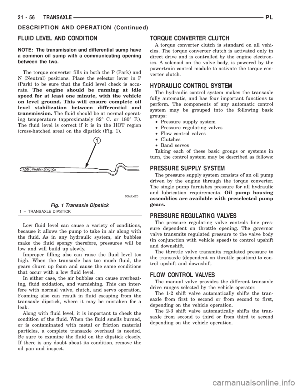
The fluid level is correct if it is in the HOT region
(cross-hatched area) on the dipstick (Fig. 1).
Low fluid level can cause a variety of conditions,
because it allows the pump to take in air along with
the fluid. As in any hydraulic system, air bubbles
make the fluid spongy therefore, pressures will be
low and will build up slowly.
Improper filling also can raise the fluid level too
high. When the transaxle has too much fluid, the
gears churn up foam and cause the same conditions
that occur with a low fluid level.
In either case, the air bubbles can cause overheat-
ing, fluid oxidation, and varnishing. This can inter-
fere with normal valve, clutch, and servo operation.
Foaming also can result in fluid escaping from the
transaxle dipstick, where it may be mistaken for a
leak.
Along with fluid level, it is important to check the
condition of the fluid. When the fluid smells burned,
or is contaminated with metal or friction material
particles, a complete transaxle overhaul is needed.
Be sure to examine the fluid on the dipstick closely.
If there is any doubt about its condition, remove the
oil pan and inspect.
TORQUE CONVERTER CLUTCH
A torque converter clutch is standard on all vehi-
cles. The torque converter clutch is activated only in
direct drive and is controlled by the engine electron-
ics. A solenoid on the valve body, is powered by the
powertrain control module to activate the torque con-
verter clutch.
HYDRAULIC CONTROL SYSTEM
The hydraulic control system makes the transaxle
fully automatic, and has four important functions to
perform. The components of any automatic control
system may be grouped into the following basic
groups:
²Pressure supply system
²Pressure regulating valves
²Flow control valves
²Clutches
²Band servos
Taking each of these basic groups or systems in
turn, the control system may be described as follows:
PRESSURE SUPPLY SYSTEM
The pressure supply system consists of an oil pump
driven by the engine through the torque converter.
The single pump furnishes pressure for all hydraulic
and lubrication requirements.Oil pump housing
assemblies are available with preselected pump
gears.
PRESSURE REGULATING VALVES
The pressure regulating valve controls line pres-
sure dependent on throttle opening. The governor
valve transmits regulated pressure to the valve body
(in conjunction with vehicle speed) to control upshift
and downshift.
The throttle valve transmits regulated pressure to
the transaxle (dependent on throttle position) to con-
trol upshift and downshift.
FLOW CONTROL VALVES
The manual valve provides the different transaxle
drive ranges selected by the vehicle operator.
The 1-2 shift valve automatically shifts the tran-
saxle from first to second or from second to first,
depending on the vehicle operation.
The 2-3 shift valve automatically shifts the tran-
saxle from second to third or from third to second
depending on the vehicle operation.
Fig. 1 Transaxle Dipstick
1 ± TRANSAXLE DIPSTICK
21 - 56 TRANSAXLEPL
DESCRIPTION AND OPERATION (Continued)
Page 971 of 1285
TORQUE CONVERTER CLUTCH SOLENOID
WIRING CONNECTOR
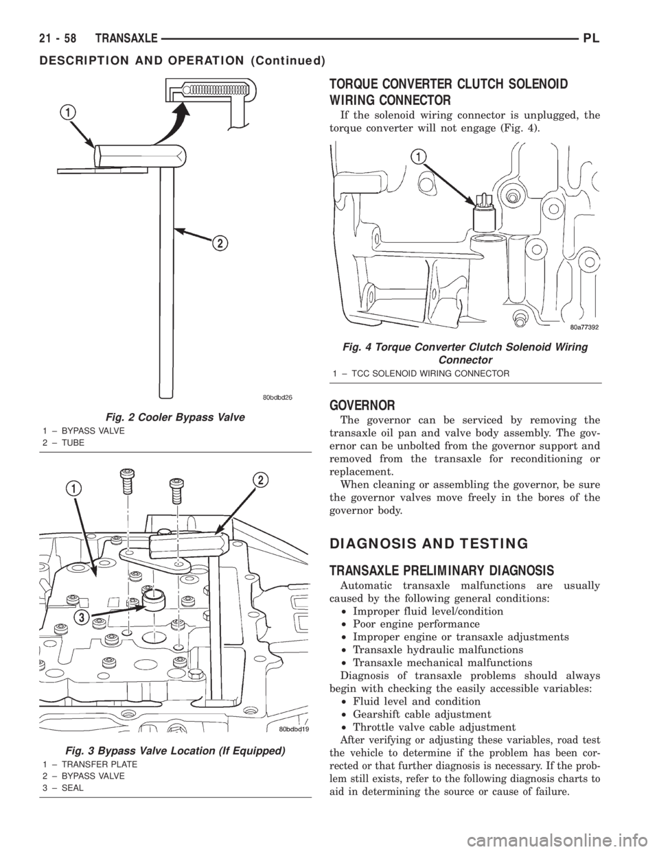
If the solenoid wiring connector is unplugged, the
torque converter will not engage (Fig. 4).
GOVERNOR
The governor can be serviced by removing the
transaxle oil pan and valve body assembly. The gov-
ernor can be unbolted from the governor support and
removed from the transaxle for reconditioning or
replacement.
When cleaning or assembling the governor, be sure
the governor valves move freely in the bores of the
governor body.
DIAGNOSIS AND TESTING
TRANSAXLE PRELIMINARY DIAGNOSIS
Automatic transaxle malfunctions are usually
caused by the following general conditions:
²Improper fluid level/condition
²Poor engine performance
²Improper engine or transaxle adjustments
²Transaxle hydraulic malfunctions
²Transaxle mechanical malfunctions
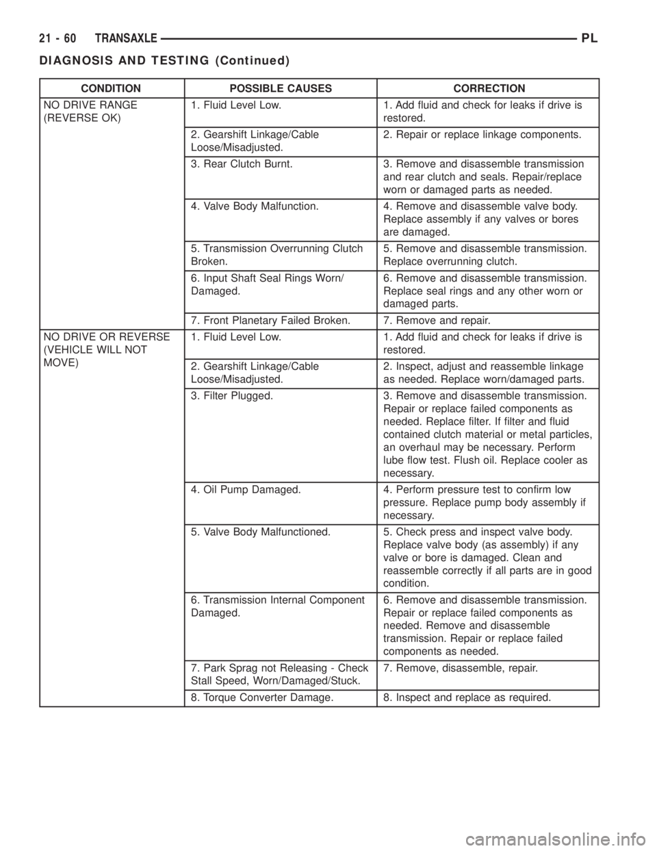
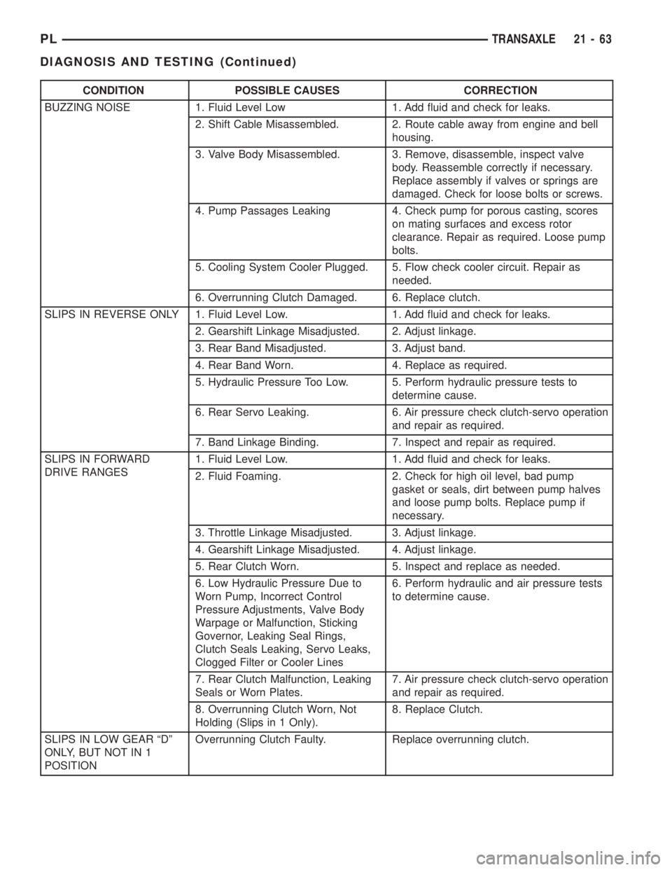
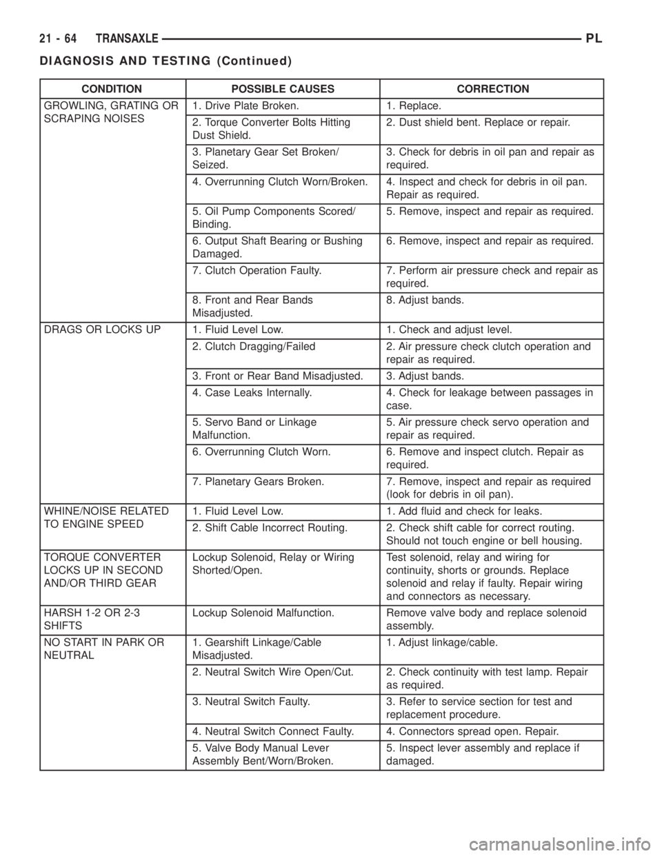
Diagnosis of transaxle problems should always
begin with checking the easily accessible variables:
²Fluid level and condition
²Gearshift cable adjustment
²Throttle valve cable adjustment
After verifying or adjusting these variables, road test
the vehicle to determine if the problem has been cor-
rected or that further diagnosis is necessary. If the prob-
lem still exists, refer to the following diagnosis charts to
aid in determining the source or cause of failure.
Fig. 2 Cooler Bypass Valve
1 ± BYPASS VALVE
2 ± TUBE
Fig. 3 Bypass Valve Location (If Equipped)
1 ± TRANSFER PLATE
2 ± BYPASS VALVE
3 ± SEAL
Fig. 4 Torque Converter Clutch Solenoid Wiring
Connector
1 ± TCC SOLENOID WIRING CONNECTOR
21 - 58 TRANSAXLEPL
DESCRIPTION AND OPERATION (Continued)
Page 972 of 1285
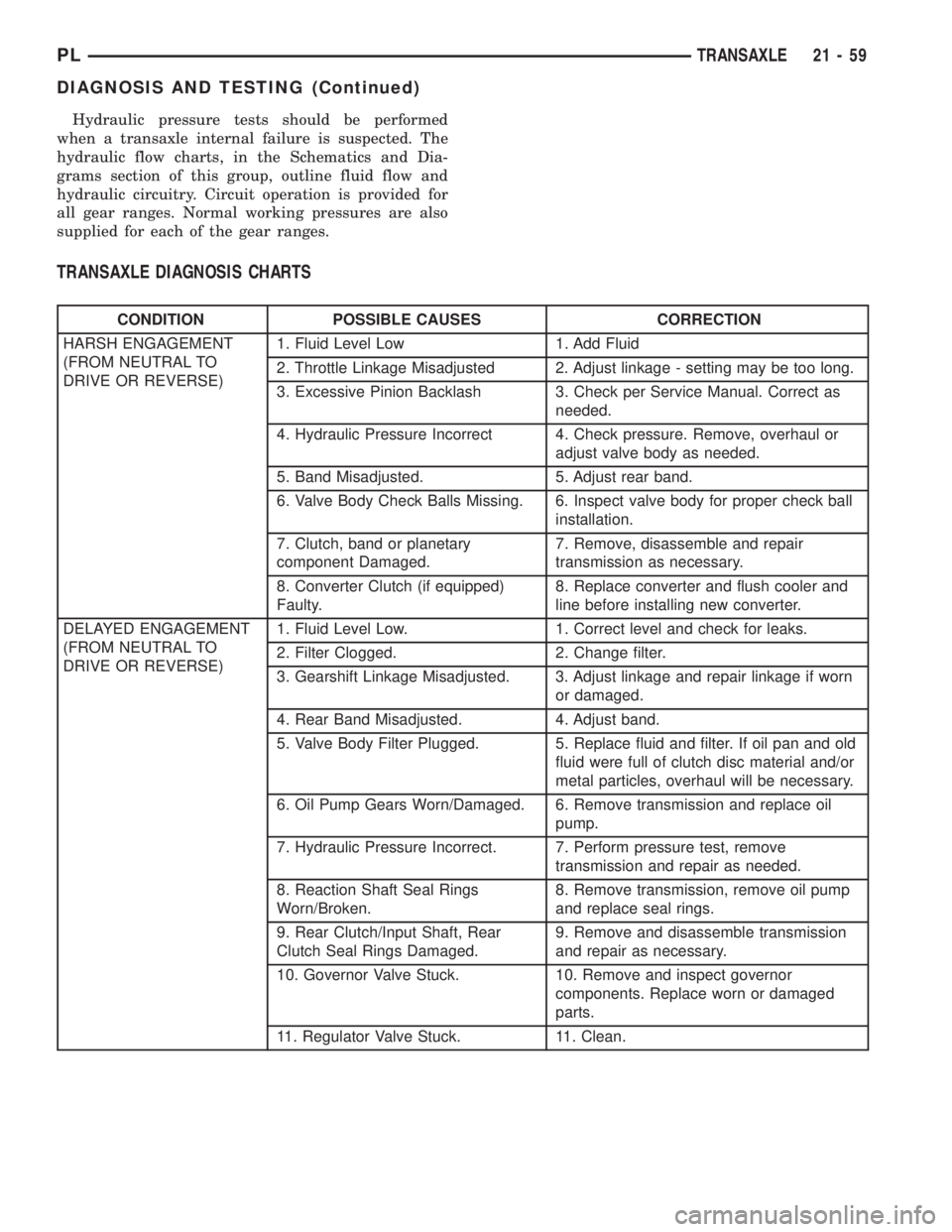
Hydraulic pressure tests should be performed
when a transaxle internal failure is suspected. The
hydraulic flow charts, in the Schematics and Dia-
grams section of this group, outline fluid flow and
hydraulic circuitry. Circuit operation is provided for
all gear ranges. Normal working pressures are also
supplied for each of the gear ranges.
TRANSAXLE DIAGNOSIS CHARTS
CONDITION POSSIBLE CAUSES CORRECTION
HARSH ENGAGEMENT
(FROM NEUTRAL TO
DRIVE OR REVERSE)1. Fluid Level Low 1. Add Fluid
2. Throttle Linkage Misadjusted 2. Adjust linkage - setting may be too long.
3. Excessive Pinion Backlash 3. Check per Service Manual. Correct as
needed.
4. Hydraulic Pressure Incorrect 4. Check pressure. Remove, overhaul or
adjust valve body as needed.
5. Band Misadjusted. 5. Adjust rear band.
6. Valve Body Check Balls Missing. 6. Inspect valve body for proper check ball
installation.
7. Clutch, band or planetary
component Damaged.7. Remove, disassemble and repair
transmission as necessary.
8. Converter Clutch (if equipped)
Faulty.8. Replace converter and flush cooler and
line before installing new converter.
DELAYED ENGAGEMENT
(FROM NEUTRAL TO
DRIVE OR REVERSE)1. Fluid Level Low. 1. Correct level and check for leaks.
2. Filter Clogged. 2. Change filter.
3. Gearshift Linkage Misadjusted. 3. Adjust linkage and repair linkage if worn
or damaged.
4. Rear Band Misadjusted. 4. Adjust band.
5. Valve Body Filter Plugged. 5. Replace fluid and filter. If oil pan and old
fluid were full of clutch disc material and/or
metal particles, overhaul will be necessary.
6. Oil Pump Gears Worn/Damaged. 6. Remove transmission and replace oil
pump.
7. Hydraulic Pressure Incorrect. 7. Perform pressure test, remove
transmission and repair as needed.
8. Reaction Shaft Seal Rings
Worn/Broken.8. Remove transmission, remove oil pump
and replace seal rings.
9. Rear Clutch/Input Shaft, Rear
Clutch Seal Rings Damaged.9. Remove and disassemble transmission
and repair as necessary.
10. Governor Valve Stuck. 10. Remove and inspect governor
components. Replace worn or damaged
parts.
11. Regulator Valve Stuck. 11. Clean.
PLTRANSAXLE 21 - 59
DIAGNOSIS AND TESTING (Continued)
Page 973 of 1285
CONDITION POSSIBLE CAUSES CORRECTION
NO DRIVE RANGE
(REVERSE OK)1. Fluid Level Low. 1. Add fluid and check for leaks if drive is
restored.
2. Gearshift Linkage/Cable
Loose/Misadjusted.2. Repair or replace linkage components.
3. Rear Clutch Burnt. 3. Remove and disassemble transmission
and rear clutch and seals. Repair/replace
worn or damaged parts as needed.
4. Valve Body Malfunction. 4. Remove and disassemble valve body.
Replace assembly if any valves or bores
are damaged.
5. Transmission Overrunning Clutch
Broken.5. Remove and disassemble transmission.
Replace overrunning clutch.
6. Input Shaft Seal Rings Worn/
Damaged.6. Remove and disassemble transmission.
Replace seal rings and any other worn or
damaged parts.
7. Front Planetary Failed Broken. 7. Remove and repair.
NO DRIVE OR REVERSE
(VEHICLE WILL NOT
MOVE)1. Fluid Level Low. 1. Add fluid and check for leaks if drive is
restored.
2. Gearshift Linkage/Cable
Loose/Misadjusted.2. Inspect, adjust and reassemble linkage
as needed. Replace worn/damaged parts.
3. Filter Plugged. 3. Remove and disassemble transmission.
Repair or replace failed components as
needed. Replace filter. If filter and fluid
contained clutch material or metal particles,
an overhaul may be necessary. Perform
lube flow test. Flush oil. Replace cooler as
necessary.
4. Oil Pump Damaged. 4. Perform pressure test to confirm low
pressure. Replace pump body assembly if
necessary.
5. Valve Body Malfunctioned. 5. Check press and inspect valve body.
Replace valve body (as assembly) if any
valve or bore is damaged. Clean and
reassemble correctly if all parts are in good
condition.
6. Transmission Internal Component
Damaged.6. Remove and disassemble transmission.
Repair or replace failed components as
needed. Remove and disassemble
transmission. Repair or replace failed
components as needed.
7. Park Sprag not Releasing - Check
Stall Speed, Worn/Damaged/Stuck.7. Remove, disassemble, repair.
8. Torque Converter Damage. 8. Inspect and replace as required.
21 - 60 TRANSAXLEPL
DIAGNOSIS AND TESTING (Continued)
Page 976 of 1285
CONDITION POSSIBLE CAUSES CORRECTION
BUZZING NOISE 1. Fluid Level Low 1. Add fluid and check for leaks.
2. Shift Cable Misassembled. 2. Route cable away from engine and bell
housing.
3. Valve Body Misassembled. 3. Remove, disassemble, inspect valve
body. Reassemble correctly if necessary.
Replace assembly if valves or springs are
damaged. Check for loose bolts or screws.
4. Pump Passages Leaking 4. Check pump for porous casting, scores
on mating surfaces and excess rotor
clearance. Repair as required. Loose pump
bolts.
5. Cooling System Cooler Plugged. 5. Flow check cooler circuit. Repair as
needed.
6. Overrunning Clutch Damaged. 6. Replace clutch.
SLIPS IN REVERSE ONLY 1. Fluid Level Low. 1. Add fluid and check for leaks.
2. Gearshift Linkage Misadjusted. 2. Adjust linkage.
3. Rear Band Misadjusted. 3. Adjust band.
4. Rear Band Worn. 4. Replace as required.
5. Hydraulic Pressure Too Low. 5. Perform hydraulic pressure tests to
determine cause.
6. Rear Servo Leaking. 6. Air pressure check clutch-servo operation
and repair as required.
7. Band Linkage Binding. 7. Inspect and repair as required.
SLIPS IN FORWARD
DRIVE RANGES1. Fluid Level Low. 1. Add fluid and check for leaks.
2. Fluid Foaming. 2. Check for high oil level, bad pump
gasket or seals, dirt between pump halves
and loose pump bolts. Replace pump if
necessary.
3. Throttle Linkage Misadjusted. 3. Adjust linkage.
4. Gearshift Linkage Misadjusted. 4. Adjust linkage.
5. Rear Clutch Worn. 5. Inspect and replace as needed.
6. Low Hydraulic Pressure Due to
Worn Pump, Incorrect Control
Pressure Adjustments, Valve Body
Warpage or Malfunction, Sticking
Governor, Leaking Seal Rings,
Clutch Seals Leaking, Servo Leaks,
Clogged Filter or Cooler Lines6. Perform hydraulic and air pressure tests
to determine cause.
7. Rear Clutch Malfunction, Leaking
Seals or Worn Plates.7. Air pressure check clutch-servo operation
and repair as required.
8. Overrunning Clutch Worn, Not
Holding (Slips in 1 Only).8. Replace Clutch.
SLIPS IN LOW GEAR ªDº
ONLY, BUT NOT IN 1
POSITIONOverrunning Clutch Faulty. Replace overrunning clutch.
PLTRANSAXLE 21 - 63
DIAGNOSIS AND TESTING (Continued)
Page 977 of 1285
CONDITION POSSIBLE CAUSES CORRECTION
GROWLING, GRATING OR
SCRAPING NOISES1. Drive Plate Broken. 1. Replace.
2. Torque Converter Bolts Hitting
Dust Shield.2. Dust shield bent. Replace or repair.
3. Planetary Gear Set Broken/
Seized.3. Check for debris in oil pan and repair as
required.
4. Overrunning Clutch Worn/Broken. 4. Inspect and check for debris in oil pan.
Repair as required.
5. Oil Pump Components Scored/
Binding.5. Remove, inspect and repair as required.
6. Output Shaft Bearing or Bushing
Damaged.6. Remove, inspect and repair as required.
7. Clutch Operation Faulty. 7. Perform air pressure check and repair as
required.
8. Front and Rear Bands
Misadjusted.8. Adjust bands.
DRAGS OR LOCKS UP 1. Fluid Level Low. 1. Check and adjust level.
2. Clutch Dragging/Failed 2. Air pressure check clutch operation and
repair as required.
3. Front or Rear Band Misadjusted. 3. Adjust bands.
4. Case Leaks Internally. 4. Check for leakage between passages in
case.
5. Servo Band or Linkage
Malfunction.5. Air pressure check servo operation and
repair as required.
6. Overrunning Clutch Worn. 6. Remove and inspect clutch. Repair as
required.
7. Planetary Gears Broken. 7. Remove, inspect and repair as required
(look for debris in oil pan).
WHINE/NOISE RELATED
TO ENGINE SPEED1. Fluid Level Low. 1. Add fluid and check for leaks.
2. Shift Cable Incorrect Routing. 2. Check shift cable for correct routing.
Should not touch engine or bell housing.
TORQUE CONVERTER
LOCKS UP IN SECOND
AND/OR THIRD GEARLockup Solenoid, Relay or Wiring
Shorted/Open.Test solenoid, relay and wiring for
continuity, shorts or grounds. Replace
solenoid and relay if faulty. Repair wiring
and connectors as necessary.
HARSH 1-2 OR 2-3
SHIFTSLockup Solenoid Malfunction. Remove valve body and replace solenoid
assembly.
NO START IN PARK OR
NEUTRAL1. Gearshift Linkage/Cable
Misadjusted.1. Adjust linkage/cable.
2. Neutral Switch Wire Open/Cut. 2. Check continuity with test lamp. Repair
as required.
3. Neutral Switch Faulty. 3. Refer to service section for test and
replacement procedure.
4. Neutral Switch Connect Faulty. 4. Connectors spread open. Repair.
5. Valve Body Manual Lever
Assembly Bent/Worn/Broken.5. Inspect lever assembly and replace if
damaged.
21 - 64 TRANSAXLEPL
DIAGNOSIS AND TESTING (Continued)
Page 978 of 1285
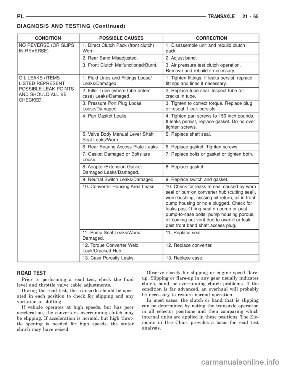
CONDITION POSSIBLE CAUSES CORRECTION
NO REVERSE (OR SLIPS
IN REVERSE)1. Direct Clutch Pack (front clutch)
Worn.1. Disassemble unit and rebuild clutch
pack.
2. Rear Band Misadjusted. 2. Adjust band.
3. Front Clutch Malfunctioned/Burnt. 3. Air pressure test clutch operation.
Remove and rebuild if necessary.
OIL LEAKS (ITEMS
LISTED REPRESENT
POSSIBLE LEAK POINTS
AND SHOULD ALL BE
CHECKED.1. Fluid Lines and Fittings Loose/
Leaks/Damaged.1. Tighten fittings. If leaks persist, replace
fittings and lines if necessary.
2. Filler Tube (where tube enters
case) Leaks/Damaged.2. Replace tube seal. Inspect tube for
cracks in tube.
3. Pressure Port Plug Loose
Loose/Damaged.3. Tighten to correct torque. Replace plug
or reseal if leak persists.
4. Pan Gasket Leaks. 4. Tighten pan screws to 150 inch pounds.
If leaks persist, replace gasket. Do no over
tighten screws.
5. Valve Body Manual Lever Shaft
Seal Leaks/Worn.5. Replace shaft seal.
6. Rear Bearing Access Plate Leaks. 6. Replace gasket. Tighten screws.
7. Gasket Damaged or Bolts are
Loose.7. Replace bolts or gasket or tighten both.
8. Adapter/Extension Gasket
Damaged Leaks/Damaged.8. Replace gasket.
9. Neutral Switch Leaks/Damaged. 9. Replace switch and gasket.
10. Converter Housing Area Leaks. 10. Check for leaks at seal caused by worn
seal or burr on converter hub (cutting seal),
worn bushing, missing oil return, oil in front
pump housing or hole plugged. Check for
leaks past O-ring seal on pump or past
pump-to-case bolts; pump housing porous,
oil coming out vent due to overfill or leak
past front band shaft access plug.
11. Pump Seal Leaks/Worn/
Damaged.11. Replace seal.
12. Torque Converter Weld
Leak/Cracked Hub.12. Replace converter.
13. Case Porosity Leaks. 13. Replace case.
ROAD TEST
Prior to performing a road test, check the fluid
level and throttle valve cable adjustments.
During the road test, the transaxle should be oper-
ated in each position to check for slipping and any
variation in shifting.
If vehicle operates at high speeds, but has poor
acceleration, the converter's overrunning clutch may
be slipping. If acceleration is normal, but high throt-
tle opening is needed for high speeds, the stator
clutch may have seized.Observe closely for slipping or engine speed flare-
up. Slipping or flare-up in any gear usually indicates
clutch, band, or overrunning clutch problems. If the
condition is far advanced, an overhaul will probably
be necessary to restore normal operation.
In most cases, the clutch or band that is slipping
can be determined by noting the transaxle operation
in all selector positions and then comparing which
internal units are applied in those positions. The Ele-
ments±in±Use Chart provides a basis for road test
analysis.
PLTRANSAXLE 21 - 65
DIAGNOSIS AND TESTING (Continued)
Page 983 of 1285
LOW AND REVERSE SERVO (REAR)
Direct air pressure into LOW/REVERSE SERVO
APPLY passage. Operation of servo is indicated by a
tightening of rear band. Spring tension on servo pis-
ton should release the band.
If clutches and servos operate properly, no upshift
indicates that a malfunction exists in the valve body.
FLUID LEAKAGE-TRANSAXLE TORQUE
CONVERTER HOUSING AREA
(1) Check for source of leakage.
(2) Since fluid leakage near the torque converter
area may be from an engine oil leak, the area should
be checked closely. Factory fill fluid is dyed red and,
therefore, can be distinguished from engine oil.
(3) Prior to removing the transaxle, perform the
following checks:
(4) When leakage is determined to originate from
the transaxle, check fluid level prior to removal of
the transaxle and torque converter.
(5) High oil level can result in oil leakage out the
vent in the dipstick. If the fluid level is high, adjust
to proper level.
(6) After performing this operation, inspect for
leakage. If a leak persists, perform the following
operation on the vehicle. This will determine if the
torque converter or transaxle is leaking.
TORQUE CONVERTER LEAKAGE
Possible sources of torque converter leakage are:
²Torque converter weld leaks at the outside diam-
eter (peripheral) weld
²Torque converter hub weld
²Torque converter impeller shell cracked adjacent
to hub
²At drive lug welds
NOTE: Hub weld is inside and not visible. Do not
attempt to repair. Replace torque converter.
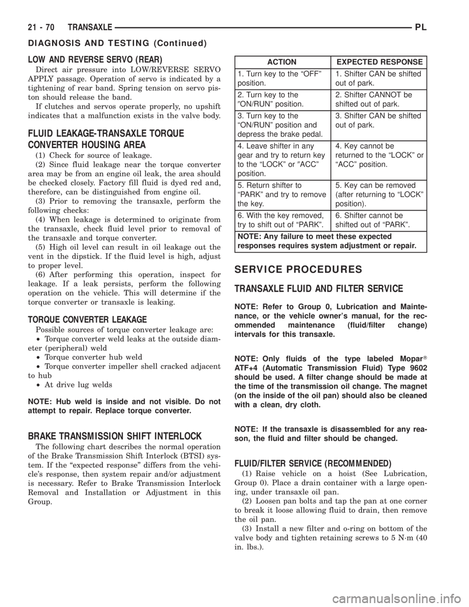
BRAKE TRANSMISSION SHIFT INTERLOCK
The following chart describes the normal operation
of the Brake Transmission Shift Interlock (BTSI) sys-
tem. If the ªexpected responseº differs from the vehi-
cle's response, then system repair and/or adjustment
is necessary. Refer to Brake Transmission Interlock
Removal and Installation or Adjustment in this
Group.
SERVICE PROCEDURES
TRANSAXLE FLUID AND FILTER SERVICE
NOTE: Refer to Group 0, Lubrication and Mainte-
nance, or the vehicle owner's manual, for the rec-
ommended maintenance (fluid/filter change)
intervals for this transaxle.
NOTE: Only fluids of the type labeled MoparT
ATF+4 (Automatic Transmission Fluid) Type 9602
should be used. A filter change should be made at
the time of the transmission oil change. The magnet
(on the inside of the oil pan) should also be cleaned
with a clean, dry cloth.
NOTE: If the transaxle is disassembled for any rea-
son, the fluid and filter should be changed.
FLUID/FILTER SERVICE (RECOMMENDED)
(1) Raise vehicle on a hoist (See Lubrication,
Group 0). Place a drain container with a large open-
ing, under transaxle oil pan.
(2) Loosen pan bolts and tap the pan at one corner
to break it loose allowing fluid to drain, then remove
the oil pan.
(3) Install a new filter and o-ring on bottom of the
valve body and tighten retaining screws to 5 N´m (40
in. lbs.).
ACTION EXPECTED RESPONSE
1. Turn key to the ªOFFº
position.1. Shifter CAN be shifted
out of park.
2. Turn key to the
9ON/RUNº position.2. Shifter CANNOT be
shifted out of park.
3. Turn key to the
ªON/RUNº position and
depress the brake pedal.3. Shifter CAN be shifted
out of park.
4. Leave shifter in any
gear and try to return key
to the ªLOCKº or9ACCº
position.4. Key cannot be
returned to the ªLOCKº or
ªACCº position.
5. Return shifter to
ªPARKº and try to remove
the key.5. Key can be removed
(after returning to ªLOCKº
position).
6. With the key removed,
try to shift out of ªPARKº.6. Shifter cannot be
shifted out of ªPARKº.
NOTE: Any failure to meet these expected
responses requires system adjustment or repair.
21 - 70 TRANSAXLEPL
DIAGNOSIS AND TESTING (Continued)