fuel pressure DODGE NEON 2000 Service Workshop Manual
[x] Cancel search | Manufacturer: DODGE, Model Year: 2000, Model line: NEON, Model: DODGE NEON 2000Pages: 1285, PDF Size: 29.42 MB
Page 845 of 1285
²All inputs monitored for proper voltage range.
²All monitored components (refer to the Emission
section for On-Board Diagnostics).
The PCM compares the upstream and downstream
heated oxygen sensor inputs to measure catalytic
convertor efficiency. If the catalyst efficiency drops
below the minimum acceptable percentage, the PCM
stores a diagnostic trouble code in memory.
During certain idle conditions, the PCM may enter
a variable idle speed strategy. During variable idle
speed strategy the PCM adjusts engine speed based
on the following inputs.
²A/C sense
²Battery voltage
²Battery temperature
²Engine coolant temperature
²Engine run time
²Power steering pressure switch
²Vehicle mileage
ACCELERATION MODE
This is a CLOSED LOOP mode. The PCM recog-
nizes an abrupt increase in Throttle Position sensor
output voltage or MAP sensor output voltage as a
demand for increased engine output and vehicle
acceleration. The PCM increases injector pulse width
in response to increased fuel demand.
DECELERATION MODE
This is a CLOSED LOOP mode. During decelera-
tion the following inputs are received by the PCM:
²A/C pressure transducer
²A/C sense
²Battery voltage
²Intake air temperature
²Engine coolant temperature
²Crankshaft position (engine speed)
²Exhaust gas oxygen content (upstream heated
oxygen sensor)
²Knock sensor
²Manifold absolute pressure
²Power steering pressure switch
²Throttle position
²IAC motor control changes in response to MAP
sensor feedback.
The PCM may receive a closed throttle input from
the Throttle Position Sensor (TPS) when it senses an
abrupt decrease in manifold pressure. This indicates
a hard deceleration. In response, the PCM may
momentarily turn off the injectors. This helps
improve fuel economy, emissions and engine braking.
If decel fuel shutoff is detected, downstream oxy-
gen sensor diagnostics is performed.WIDE-OPEN-THROTTLE MODE
This is an OPEN LOOP mode. During wide-open-
throttle operation, the following inputs are received
by the PCM:
²Intake air temperature
²Engine coolant temperature
²Engine speed
²Knock sensor
²Manifold absolute pressure
²Throttle position
When the PCM senses a wide-open-throttle condi-
tion through the Throttle Position Sensor (TPS) it de-
energizes the A/C compressor clutch relay. This
disables the air conditioning system.
The PCM does not monitor the heated oxygen sen-
sor inputs during wide-open-throttle operation except
for downstream heated oxygen sensor and both
shorted diagnostics. The PCM adjusts injector pulse
width to supply a predetermined amount of addi-
tional fuel.
IGNITION SWITCH OFF MODE
When the operator turns the ignition switch to the
OFF position, the following occurs:
²All outputs are turned off, unless 02 Heater
Monitor test is being run. Refer to the Emission sec-
tion for On-Board Diagnostics.
²No inputs are monitored except for the heated
oxygen sensors. The PCM monitors the heating ele-
ments in the oxygen sensors and then shuts down.
SYSTEM DIAGNOSIS
OPERATION
The PCM can test many of its own input and out-
put circuits. If the PCM senses a fault in a major
system, the PCM stores a Diagnostic Trouble Code
(DTC) in memory.
For DTC information see On-Board Diagnostics.
POWER DISTRIBUTION CENTER
The Power Distribution Center (PDC) is located
next to the battery (Fig. 1). The PDC contains the
starter relay, radiator fan relay, A/C compressor
clutch relay, auto shutdown relay, fuel pump relay
and several fuses.
POWERTRAIN CONTROL MODULE
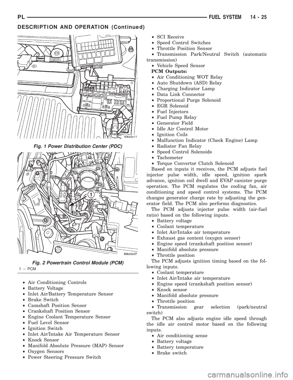
The Powertrain Control Module (PCM) is a digital
computer containing a microprocessor (Fig. 2). The
PCM receives input signals from various switches
and sensors that are referred to as PCM Inputs.
Based on these inputs, the PCM adjusts various
engine and vehicle operations through devices that
are referred to as PCM Outputs.
PCM Inputs:
14 - 24 FUEL SYSTEMPL
DESCRIPTION AND OPERATION (Continued)
Page 846 of 1285
²Air Conditioning Controls
²Battery Voltage
²Inlet Air/Battery Temperature Sensor
²Brake Switch
²Camshaft Position Sensor
²Crankshaft Position Sensor
²Engine Coolant Temperature Sensor
²Fuel Level Sensor
²Ignition Switch
²Inlet Air/Intake Air Temperature Sensor
²Knock Sensor
²Manifold Absolute Pressure (MAP) Sensor
²Oxygen Sensors
²Power Steering Pressure Switch²SCI Receive
²Speed Control Switches
²Throttle Position Sensor
²Transmission Park/Neutral Switch (automatic
transmission)
²Vehicle Speed Sensor
PCM Outputs:
²Air Conditioning WOT Relay
²Auto Shutdown (ASD) Relay
²Charging Indicator Lamp
²Data Link Connector
²Proportional Purge Solenoid
²EGR Solenoid
²Fuel Injectors
²Fuel Pump Relay
²Generator Field
²Idle Air Control Motor
²Ignition Coils
²Malfunction Indicator (Check Engine) Lamp
²Radiator Fan Relay
²Speed Control Solenoids
²Tachometer
²Torque Convertor Clutch Solenoid
Based on inputs it receives, the PCM adjusts fuel
injector pulse width, idle speed, ignition spark
advance, ignition coil dwell and EVAP canister purge
operation. The PCM regulates the cooling fan, air
conditioning and speed control systems. The PCM
changes generator charge rate by adjusting the gen-
erator field. The PCM also performs diagnostics.
The PCM adjusts injector pulse width (air-fuel
ratio) based on the following inputs.
²Battery voltage
²Coolant temperature
²Inlet Air/Intake air temperature
²Exhaust gas content (oxygen sensor)
²Engine speed (crankshaft position sensor)
²Manifold absolute pressure
²Throttle position
The PCM adjusts ignition timing based on the fol-
lowing inputs.
²Coolant temperature
²Inlet Air/Intake air temperature
²Engine speed (crankshaft position sensor)
²Knock sensor
²Manifold absolute pressure
²Throttle position
²Transmission gear selection (park/neutral
switch)
The PCM also adjusts engine idle speed through
the idle air control motor based on the following
inputs.
²Air conditioning sense
²Battery voltage
²Battery temperature
²Brake switch
Fig. 1 Power Distribution Center (PDC)
Fig. 2 Powertrain Control Module (PCM)
1 ± PCM
PLFUEL SYSTEM 14 - 25
DESCRIPTION AND OPERATION (Continued)
Page 847 of 1285
²Coolant temperature
²Engine speed (crankshaft position sensor)
²Engine run time
²Manifold absolute pressure
²Power steering pressure switch
²Throttle position
²Transmission gear selection (park/neutral
switch)
²Vehicle distance (speed)
The Auto Shutdown (ASD) and fuel pump relays
are mounted externally, but turned on and off by the
PCM.
The crankshaft position sensor signal is sent to the
PCM. If the PCM does not receive the signal within
approximately one second of engine cranking, it deac-
tivates the ASD relay and fuel pump relay. When
these relays deactivate, power is shut off from the
fuel injectors, ignition coils, heating element in the
oxygen sensors and the fuel pump.
The PCM contains a voltage converter that
changes battery voltage to a regulated 8 volts direct
current to power the camshaft position sensor, crank-
shaft position sensor and vehicle speed sensor. The
PCM also provides a 5 volt direct current supply for
the manifold absolute pressure sensor and throttle
position sensor.
PCM GROUND
OPERATION
Ground is provided through multiple pins of the
PCM connector. Depending on the vehicle there may
be as many as three different ground pins. There are
power grounds and sensor grounds.
The power grounds are used to control the ground
side of any relay, solenoid, ignition coil or injector.
The signal ground is used for any input that uses
sensor return for ground, and the ground side of any
internal processing component.
The SBEC III case is shielded to prevent RFI and
EMI. The PCM case is grounded and must be firmly
attached to a good, clean body ground.
Internally all grounds are connected together, how-
ever there is noise suppression on the sensor ground.
For EMI and RFI protection the case is also
grounded separately from the ground pins.
5 VOLT SUPPLYÐPCM OUTPUT
OPERATION
The PCM supplies 5 volts to the following sensors:
²A/C pressure transducer
²Engine coolant temperature sensor
²Manifold absolute pressure sensor
²Throttle position sensor
²Linear EGR solenoid
8-VOLT SUPPLYÐPCM OUTPUT
OPERATION
The PCM supplies 8 volts to the crankshaft posi-
tion sensor, camshaft position sensor.
FUEL CORRECTION or ADAPTIVE MEMORIES
DESCRIPTION
In Open Loop, the PCM changes pulse width with-
out feedback from the O2 Sensors. Once the engine
warms up to approximately 30 to 35É F, the PCM
goes into closed loopShort Term Correctionand
utilitzes feedback from the O2 Sensors. Closed loop
Long Term Adaptive Memoryis maintained above
170É to 190É F unless the PCM senses wide open
throttle. At that time the PCM returns to Open Loop
operation.
OPERATION
Short Term
The first fuel correction program that begins func-
tioning is the short term fuel correction. This system
corrects fuel delivery in direct proportion to the read-
ings from the Upstream O2 Sensor.
The PCM monitors the air/fuel ratio by using the
input voltage from the O2 Sensor. When the voltage
reaches its preset high or low limit, the PCM begins
to add or remove fuel until the sensor reaches its
switch point. The short term corrections then begin.
The PCM makes a series of quick changes in the
injector pulse-width until the O2 Sensor reaches its
opposite preset limit or switch point. The process
then repeats itself in the opposite direction.
Short term fuel correction will keep increasing or
decreasing injector pulse-width based upon the
upstream O2 Sensor input. The maximum range of
authority for short term memory is 25% (+/-) of base
pulse-width.
Long Term
The second fuel correction program is the long
term adaptive memory. In order to maintain correct
emission throughout all operating ranges of the
engine, a cell structure based on engine rpm and load
(MAP) is used.
There are up to 16 cells. Two cells are used only
during idle, based upon TPS and Park/Neutral
switch inputs. There may be two other cells used for
deceleration, based on TPS, engine rpm, and vehicle
speed. The other twelve cells represent a manifold
pressure and an rpm range. Six of the cells are high
rpm and the other six are low rpm. Each of these
cells is a specific MAP voltage range.
14 - 26 FUEL SYSTEMPL
DESCRIPTION AND OPERATION (Continued)
Page 848 of 1285
As the engine enters one of these cells the PCM
looks at the amount of short term correction being
used. Because the goal is to keep short term at 0 (O2
Sensor switching at 0.5 volt), long term will update
in the same direction as short term correction was
moving to bring the short term back to 0. Once short
term is back at 0, this long term correction factor is
stored in memory.
The values stored in long term adaptive memory
are used for all operating conditions, including open
loop. However, the updating of the long term memoryoccurs after the engine has exceeded approximately
17É F, with fuel control in closed loop and two min-
utes of engine run time. This is done to prevent any
transitional temperature or start-up compensations
from corrupting long term fuel correction.
Long term adaptive memory can change the pulse-
width by as much as 25%, which means it can correct
for all of short term. It is possible to have a problem
that would drive long term to 25% and short term to
another 25% for a total change of 50% away from
base pulse-width calculation.
TYPICAL ADAPTIVE MEMORY FUEL CELLS
Open
ThrottleOpen
ThrottleOpen
ThrottleOpen
ThrottleOpen
ThrottleOpen
Throttle Idle Decel
Vacuum 20 17 13 9 5 0
Above 1,984
rpm1 3 5 7 9 11 13 Drive 15
Below 1,984
rpm02 4 6 8 1012
Neutral14
MAP volt =0 1.4 2.0 2.6 3.3 3.9
Fuel Correction Diagnostics
There are two fuel correction diagnostic routines:
²Fuel System Rich
²Fuel System Lean
A DTC is set and the MIL is illuminated if the
PCM detects either of these conditions.
PROGRAMMABLE COMMUNICATIONS
INTERFACE (PCI) BUS
OPERATION
Various modules exchange information through a
communications port called the PCI Bus. The Power-
train Control Module (PCM) transmits the Malfunc-
tion Indicator Lamp (Check Engine) On/Off signal
and engine RPM on the PCI Bus. The PCM receives
the Air Conditioning select input, transaxle gear
position inputs over the PCI Bus. The PCM also
receives the air conditioning evaporator temperature
signal from the PCI Bus.
The following components access or send informa-
tion on the PCI Bus.
²Instrument Panel
²Body Control Module
²Air Bag System Diagnostic Module
²Full ATC Display Head
²ABS Module
²Transmission Control Module
²Powertrain Control Module
²Overhead Travel Module
AIR CONDITIONING PRESSURE
TRANSDUCERÐPCM INPUT
OPERATION
The Powertrain Control Module (PCM) monitors
the A/C compressor discharge (high side) pressure
through the air conditioning pressure transducer.
The transducer supplies an input to the PCM. The
PCM engages the A/C compressor clutch if pressure
is sufficient for A/C system operation.
AUTOMATIC SHUTDOWN (ASD) SENSEÐPCM
INPUT
OPERATION
The ASD sense circuit informs the PCM when the
ASD relay energizes. A 12 volt signal at this input
indicates to the PCM that the ASD has been acti-
vated. This input is used only to sense that the ASD
relay is energized.
When energized, the ASD relay supplies battery
voltage to the fuel injectors, ignition coils and the
heating element in each oxygen sensor. If the PCM
does not receive 12 volts from this input after
grounding the ASD relay, it sets a Diagnostic Trouble
Code (DTC).
PLFUEL SYSTEM 14 - 27
DESCRIPTION AND OPERATION (Continued)
Page 856 of 1285
OPERATION
When the knock sensor detects a knock in one of
the cylinders, it sends an input signal to the PCM. In
response, the PCM retards ignition timing for all cyl-
inders by a scheduled amount.
Knock sensors contain a piezoelectric material
which sends an input voltage (signal) to the PCM. As
the intensity of the engine knock vibration increases,
the knock sensor output voltage also increases.
The voltage signal produced by the knock sensor
increases with the amplitude of vibration. The PCM
receives as an input the knock sensor voltage signal.
If the signal rises above a predetermined level, the
PCM will store that value in memory and retard
ignition timing to reduce engine knock. If the knock
sensor voltage exceeds a preset value, the PCM
retards ignition timing for all cylinders. It is not a
selective cylinder retard.
The PCM ignores knock sensor input during engine
idle conditions. Once the engine speed exceeds a
specified value, knock retard is allowed.
Knock retard uses its own short term and long
term memory program.
Long term memory stores previous detonation
information in its battery-backed RAM. The maxi-
mum authority that long term memory has over tim-
ing retard can be calibrated.
Short term memory is allowed to retard timing up
to a preset amount under all operating conditions (as
long as rpm is above the minimum rpm) except WOT.
The PCM, using short term memory, can respond
quickly to retard timing when engine knock is
detected. Short term memory is lost any time the
ignition key is turned off.
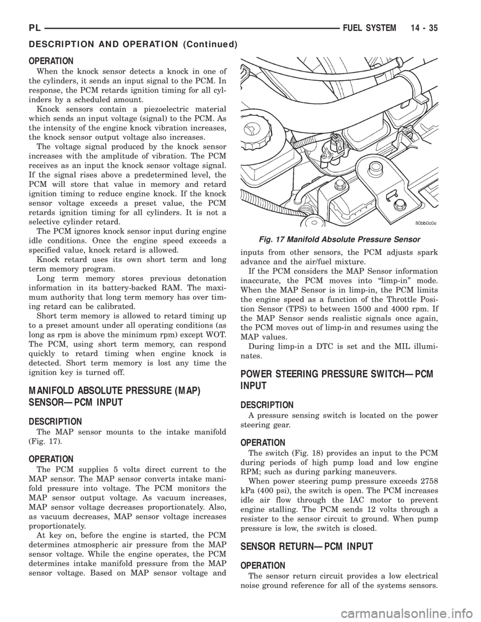
MANIFOLD ABSOLUTE PRESSURE (MAP)
SENSORÐPCM INPUT
DESCRIPTION
The MAP sensor mounts to the intake manifold
(Fig. 17).
OPERATION
The PCM supplies 5 volts direct current to the
MAP sensor. The MAP sensor converts intake mani-
fold pressure into voltage. The PCM monitors the
MAP sensor output voltage. As vacuum increases,
MAP sensor voltage decreases proportionately. Also,
as vacuum decreases, MAP sensor voltage increases
proportionately.
At key on, before the engine is started, the PCM
determines atmospheric air pressure from the MAP
sensor voltage. While the engine operates, the PCM
determines intake manifold pressure from the MAP
sensor voltage. Based on MAP sensor voltage andinputs from other sensors, the PCM adjusts spark
advance and the air/fuel mixture.
If the PCM considers the MAP Sensor information
inaccurate, the PCM moves into ªlimp-inº mode.
When the MAP Sensor is in limp-in, the PCM limits
the engine speed as a function of the Throttle Posi-
tion Sensor (TPS) to between 1500 and 4000 rpm. If
the MAP Sensor sends realistic signals once again,
the PCM moves out of limp-in and resumes using the
MAP values.
During limp-in a DTC is set and the MIL illumi-
nates.
POWER STEERING PRESSURE SWITCHÐPCM
INPUT
DESCRIPTION
A pressure sensing switch is located on the power
steering gear.
OPERATION
The switch (Fig. 18) provides an input to the PCM
during periods of high pump load and low engine
RPM; such as during parking maneuvers.
When power steering pump pressure exceeds 2758
kPa (400 psi), the switch is open. The PCM increases
idle air flow through the IAC motor to prevent
engine stalling. The PCM sends 12 volts through a
resister to the sensor circuit to ground. When pump
pressure is low, the switch is closed.
SENSOR RETURNÐPCM INPUT
OPERATION
The sensor return circuit provides a low electrical
noise ground reference for all of the systems sensors.
Fig. 17 Manifold Absolute Pressure Sensor
PLFUEL SYSTEM 14 - 35
DESCRIPTION AND OPERATION (Continued)
Page 857 of 1285
The sensor return circuit connects to internal ground
circuits within the Powertrain Control Module
(PCM).
SPEED CONTROLÐPCM INPUT
OPERATION
The speed control system provides five separate
voltages (inputs) to the Powertrain Control Module
(PCM). The voltages correspond to the ON, OFF,
SET, RESUME, CANCEL, and COAST.
The speed control ON voltage informs the PCM
that the speed control system has been activated.
The speed control SET voltage informs the PCM that
a fixed vehicle speed has been selected. The speed
control RESUME voltage indicates the previous fixed
speed is requested. The speed control CANCEL volt-
age tells the PCM to deactivate but retain set speed
in memory (same as depressing the brake pedal). The
speed control OFF voltage tells the PCM that the
speed control system has deactivated.
Inputs Required for Operation
The inputs required by the PCM to operate the
Speed Control System include:
²Speed Control switches
²Brake switch
²Park/Neutral switch
²Vehicle speed signal
²Engine speed
²CCD bussed message from TCM
SCI RECEIVEÐPCM INPUT
OPERATION
SCI Receive is the serial data communication
receive circuit for the DRB scan tool. The PowertrainControl Module (PCM) receives data from the DRB
through the SCI Receive circuit.
PARK/NEUTRAL POSITION SWITCHÐPCM
INPUT
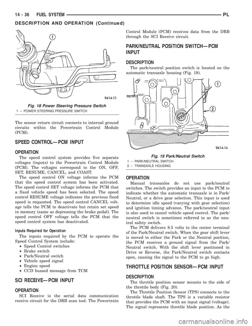
DESCRIPTION
The park/neutral position switch is located on the
automatic transaxle housing (Fig. 19).
OPERATION
Manual transaxles do not use park/neutral
switches. The switch provides an input to the PCM to
indicate whether the automatic transaxle is in Park/
Neutral, or a drive gear selection. This input is used
to determine idle speed (varying with gear selection)
and ignition timing advance. The park/neutral input
is also used to cancel vehicle speed control. The park/
neutral switch is sometimes referred to as the neu-
tral safety switch.
The PCM delivers 8.5 volts to the center terminal
of the Park/Neutral switch. When the gear shift lever
is moved to either the Park or the Neutral position,
the PCM receives a ground signal from the Park/
Neutral switch. With the shift lever positioned in
Drive or Reverse, the Park/Neutral switch contacts
open, causing the signal to the PCM to go high.
THROTTLE POSITION SENSORÐPCM INPUT
DESCRIPTION
The throttle position sensor mounts to the side of
the throttle body (Fig. 20).
The Throttle Position Sensor (TPS) connects to the
throttle blade shaft. The TPS is a variable resistor
that provides the PCM with an input signal (voltage).
The signal represents throttle blade position. As the
Fig. 18 Power Steering Pressure Switch
1 ± POWER STEERING PRESSURE SWITCH
Fig. 19 Park/Neutral Switch
1 ± PARK/NEUTRAL SWITCH
2 ± TRANSAXLE HOUSING
14 - 36 FUEL SYSTEMPL
DESCRIPTION AND OPERATION (Continued)
Page 860 of 1285
PROPORTIONAL PURGE SOLENOIDÐPCM
OUTPUT
DESCRIPTION
OPERATION
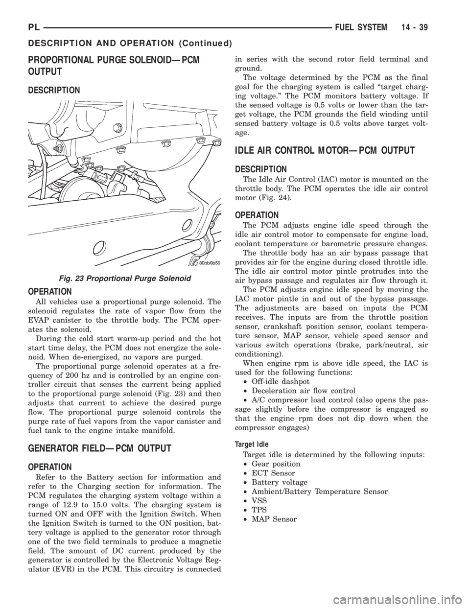
All vehicles use a proportional purge solenoid. The
solenoid regulates the rate of vapor flow from the
EVAP canister to the throttle body. The PCM oper-
ates the solenoid.
During the cold start warm-up period and the hot
start time delay, the PCM does not energize the sole-
noid. When de-energized, no vapors are purged.
The proportional purge solenoid operates at a fre-
quency of 200 hz and is controlled by an engine con-
troller circuit that senses the current being applied
to the proportional purge solenoid (Fig. 23) and then
adjusts that current to achieve the desired purge
flow. The proportional purge solenoid controls the
purge rate of fuel vapors from the vapor canister and
fuel tank to the engine intake manifold.
GENERATOR FIELDÐPCM OUTPUT
OPERATION
Refer to the Battery section for information and
refer to the Charging section for information. The
PCM regulates the charging system voltage within a
range of 12.9 to 15.0 volts. The charging system is
turned ON and OFF with the Ignition Switch. When
the Ignition Switch is turned to the ON position, bat-
tery voltage is applied to the generator rotor through
one of the two field terminals to produce a magnetic
field. The amount of DC current produced by the
generator is controlled by the Electronic Voltage Reg-
ulator (EVR) in the PCM. This circuitry is connectedin series with the second rotor field terminal and
ground.
The voltage determined by the PCM as the final
goal for the charging system is called ªtarget charg-
ing voltage.º The PCM monitors battery voltage. If
the sensed voltage is 0.5 volts or lower than the tar-
get voltage, the PCM grounds the field winding until
sensed battery voltage is 0.5 volts above target volt-
age.
IDLE AIR CONTROL MOTORÐPCM OUTPUT
DESCRIPTION
The Idle Air Control (IAC) motor is mounted on the
throttle body. The PCM operates the idle air control
motor (Fig. 24).
OPERATION
The PCM adjusts engine idle speed through the
idle air control motor to compensate for engine load,
coolant temperature or barometric pressure changes.
The throttle body has an air bypass passage that
provides air for the engine during closed throttle idle.
The idle air control motor pintle protrudes into the
air bypass passage and regulates air flow through it.
The PCM adjusts engine idle speed by moving the
IAC motor pintle in and out of the bypass passage.
The adjustments are based on inputs the PCM
receives. The inputs are from the throttle position
sensor, crankshaft position sensor, coolant tempera-
ture sensor, MAP sensor, vehicle speed sensor and
various switch operations (brake, park/neutral, air
conditioning).
When engine rpm is above idle speed, the IAC is
used for the following functions:
²Off-idle dashpot
²Deceleration air flow control
²A/C compressor load control (also opens the pas-
sage slightly before the compressor is engaged so
that the engine rpm does not dip down when the
compressor engages)
Target Idle
Target idle is determined by the following inputs:
²Gear position
²ECT Sensor
²Battery voltage
²Ambient/Battery Temperature Sensor
²VSS
²TPS
²MAP Sensor
Fig. 23 Proportional Purge Solenoid
PLFUEL SYSTEM 14 - 39
DESCRIPTION AND OPERATION (Continued)
Page 870 of 1285
SPECIFICATIONS
VECI LABEL
Always use the information found on the Vehicle
Emission Control Information (VECI) label. The
VECI label is located in the engine compartment.
TORQUE
DESCRIPTION TORQUE
Air Cleaner Lid Screws...... 3.9N´m(35in.lbs.)
Crankshaft Position Sensor Mounting Bolts . . 8 N´m
(70 in. lbs.)
Engine Coolant Temperature Sensor...... 18N´m
(165 in. lbs.)
IAC Motor-To-Throttle Body Bolts....... 4.5N´m
(40 in. lbs.)
MAP Sensor............... 4.5N´m(40in.lbs.)
Oxygen Sensor............. 28N´m(20ft.lbs.)
Powertrain Control Module (PCM) Mounting
Screws.................. 4N´m(35in.lbs.)
Throttle Body Mounting Bolts........... 23N´m
(200 in. lbs.)
Throttle Position Sensor Mounting Screws . . 2 N´m
(20 in. lbs.)
Vehicle Speed Sensor Mounting Bolt..... 2.2N´m
(20 in. lbs.)
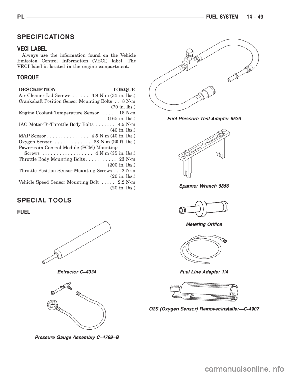
SPECIAL TOOLS
FUEL
Extractor C±4334
Pressure Gauge Assembly C±4799±B
Fuel Pressure Test Adapter 6539
Spanner Wrench 6856
Metering Orifice
Fuel Line Adapter 1/4
O2S (Oxygen Sensor) Remover/InstallerÐC-4907
PLFUEL SYSTEM 14 - 49
Page 1075 of 1285
SERVICE PROCEDURES
PRESSURE GAUGES
A quality air pressure gauge is recommended to
check tire pressure. After checking the air pressure,
replace valve cap finger tight.
TIRE INFLATION PRESSURES
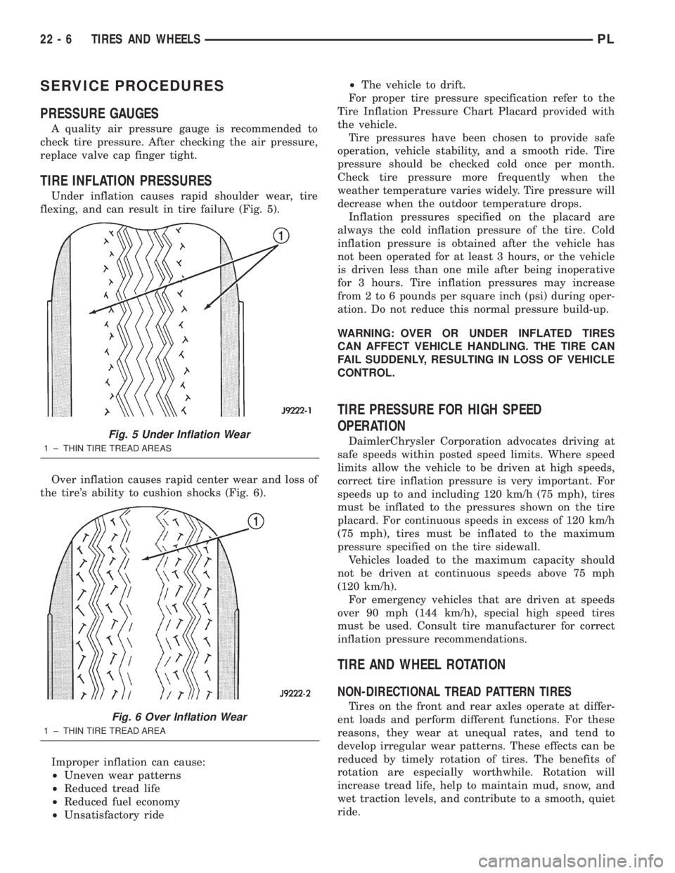
Under inflation causes rapid shoulder wear, tire
flexing, and can result in tire failure (Fig. 5).
Over inflation causes rapid center wear and loss of
the tire's ability to cushion shocks (Fig. 6).
Improper inflation can cause:
²Uneven wear patterns
²Reduced tread life
²Reduced fuel economy
²Unsatisfactory ride²The vehicle to drift.
For proper tire pressure specification refer to the
Tire Inflation Pressure Chart Placard provided with
the vehicle.
Tire pressures have been chosen to provide safe
operation, vehicle stability, and a smooth ride. Tire
pressure should be checked cold once per month.
Check tire pressure more frequently when the
weather temperature varies widely. Tire pressure will
decrease when the outdoor temperature drops.
Inflation pressures specified on the placard are
always the cold inflation pressure of the tire. Cold
inflation pressure is obtained after the vehicle has
not been operated for at least 3 hours, or the vehicle
is driven less than one mile after being inoperative
for 3 hours. Tire inflation pressures may increase
from 2 to 6 pounds per square inch (psi) during oper-
ation. Do not reduce this normal pressure build-up.
WARNING: OVER OR UNDER INFLATED TIRES
CAN AFFECT VEHICLE HANDLING. THE TIRE CAN
FAIL SUDDENLY, RESULTING IN LOSS OF VEHICLE
CONTROL.
TIRE PRESSURE FOR HIGH SPEED
OPERATION
DaimlerChrysler Corporation advocates driving at
safe speeds within posted speed limits. Where speed
limits allow the vehicle to be driven at high speeds,
correct tire inflation pressure is very important. For
speeds up to and including 120 km/h (75 mph), tires
must be inflated to the pressures shown on the tire
placard. For continuous speeds in excess of 120 km/h
(75 mph), tires must be inflated to the maximum
pressure specified on the tire sidewall.
Vehicles loaded to the maximum capacity should
not be driven at continuous speeds above 75 mph
(120 km/h).
For emergency vehicles that are driven at speeds
over 90 mph (144 km/h), special high speed tires
must be used. Consult tire manufacturer for correct
inflation pressure recommendations.
TIRE AND WHEEL ROTATION
NON-DIRECTIONAL TREAD PATTERN TIRES
Tires on the front and rear axles operate at differ-
ent loads and perform different functions. For these
reasons, they wear at unequal rates, and tend to
develop irregular wear patterns. These effects can be
reduced by timely rotation of tires. The benefits of
rotation are especially worthwhile. Rotation will
increase tread life, help to maintain mud, snow, and
wet traction levels, and contribute to a smooth, quiet
ride.
Fig. 5 Under Inflation Wear
1 ± THIN TIRE TREAD AREAS
Fig. 6 Over Inflation Wear
1 ± THIN TIRE TREAD AREA
22 - 6 TIRES AND WHEELSPL
Page 1093 of 1285
OPERATION
BULB CHECK
Each time the ignition key is turned to the ON
position, the malfunction indicator (check engine)
lamp on the instrument panel should illuminate for
approximately 2 seconds then go out. This is done for
a bulb check.
OBTAINING DTC'S USING DRB SCAN TOOL
(1) Connect the DRB scan tool to the data link
(diagnostic) connector. This connector is located inthe passenger compartment; at the lower edge of
instrument panel; near the steering column.
(2) Turn the ignition switch on and access the
ªRead Faultº screen.
(3) Record all the DTC's and ªfreeze frameº infor-
mation shown on the DRB scan tool.
(4) To erase DTC's, use the ªErase Trouble Codeº
data screen on the DRB scan tool.Do not erase any
DTC's until problems have been investigated
and repairs have been performed.
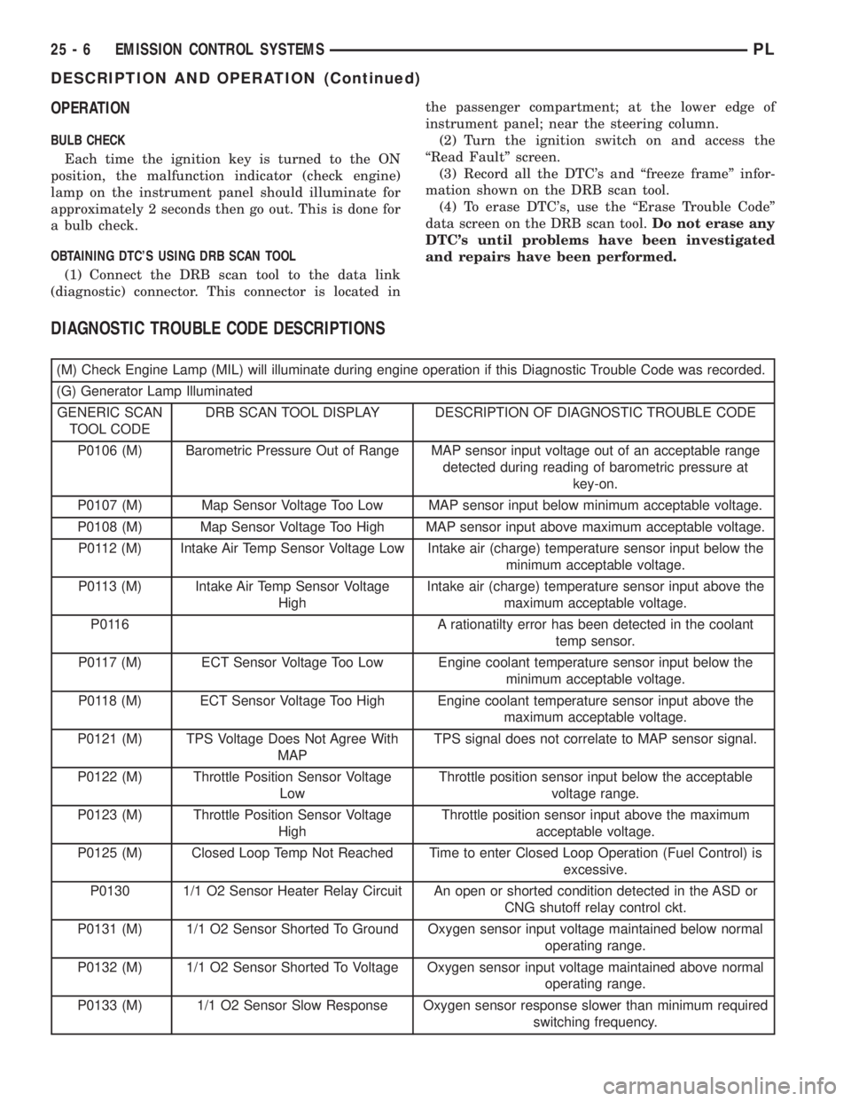
DIAGNOSTIC TROUBLE CODE DESCRIPTIONS
(M) Check Engine Lamp (MIL) will illuminate during engine operation if this Diagnostic Trouble Code was recorded.
(G) Generator Lamp Illuminated
GENERIC SCAN
TOOL CODEDRB SCAN TOOL DISPLAY DESCRIPTION OF DIAGNOSTIC TROUBLE CODE
P0106 (M) Barometric Pressure Out of Range MAP sensor input voltage out of an acceptable range
detected during reading of barometric pressure at
key-on.
P0107 (M) Map Sensor Voltage Too Low MAP sensor input below minimum acceptable voltage.
P0108 (M) Map Sensor Voltage Too High MAP sensor input above maximum acceptable voltage.
P0112 (M) Intake Air Temp Sensor Voltage Low Intake air (charge) temperature sensor input below the
minimum acceptable voltage.
P0113 (M) Intake Air Temp Sensor Voltage
HighIntake air (charge) temperature sensor input above the
maximum acceptable voltage.
P0116 A rationatilty error has been detected in the coolant
temp sensor.
P0117 (M) ECT Sensor Voltage Too Low Engine coolant temperature sensor input below the
minimum acceptable voltage.
P0118 (M) ECT Sensor Voltage Too High Engine coolant temperature sensor input above the
maximum acceptable voltage.
P0121 (M) TPS Voltage Does Not Agree With
MAPTPS signal does not correlate to MAP sensor signal.
P0122 (M) Throttle Position Sensor Voltage
LowThrottle position sensor input below the acceptable
voltage range.
P0123 (M) Throttle Position Sensor Voltage
HighThrottle position sensor input above the maximum
acceptable voltage.
P0125 (M) Closed Loop Temp Not Reached Time to enter Closed Loop Operation (Fuel Control) is
excessive.
P0130 1/1 O2 Sensor Heater Relay Circuit An open or shorted condition detected in the ASD or
CNG shutoff relay control ckt.
P0131 (M) 1/1 O2 Sensor Shorted To Ground Oxygen sensor input voltage maintained below normal
operating range.
P0132 (M) 1/1 O2 Sensor Shorted To Voltage Oxygen sensor input voltage maintained above normal
operating range.
P0133 (M) 1/1 O2 Sensor Slow Response Oxygen sensor response slower than minimum required
switching frequency.
25 - 6 EMISSION CONTROL SYSTEMSPL
DESCRIPTION AND OPERATION (Continued)