auxiliary battery DODGE NEON 2000 Service Repair Manual
[x] Cancel search | Manufacturer: DODGE, Model Year: 2000, Model line: NEON, Model: DODGE NEON 2000Pages: 1285, PDF Size: 29.42 MB
Page 252 of 1285
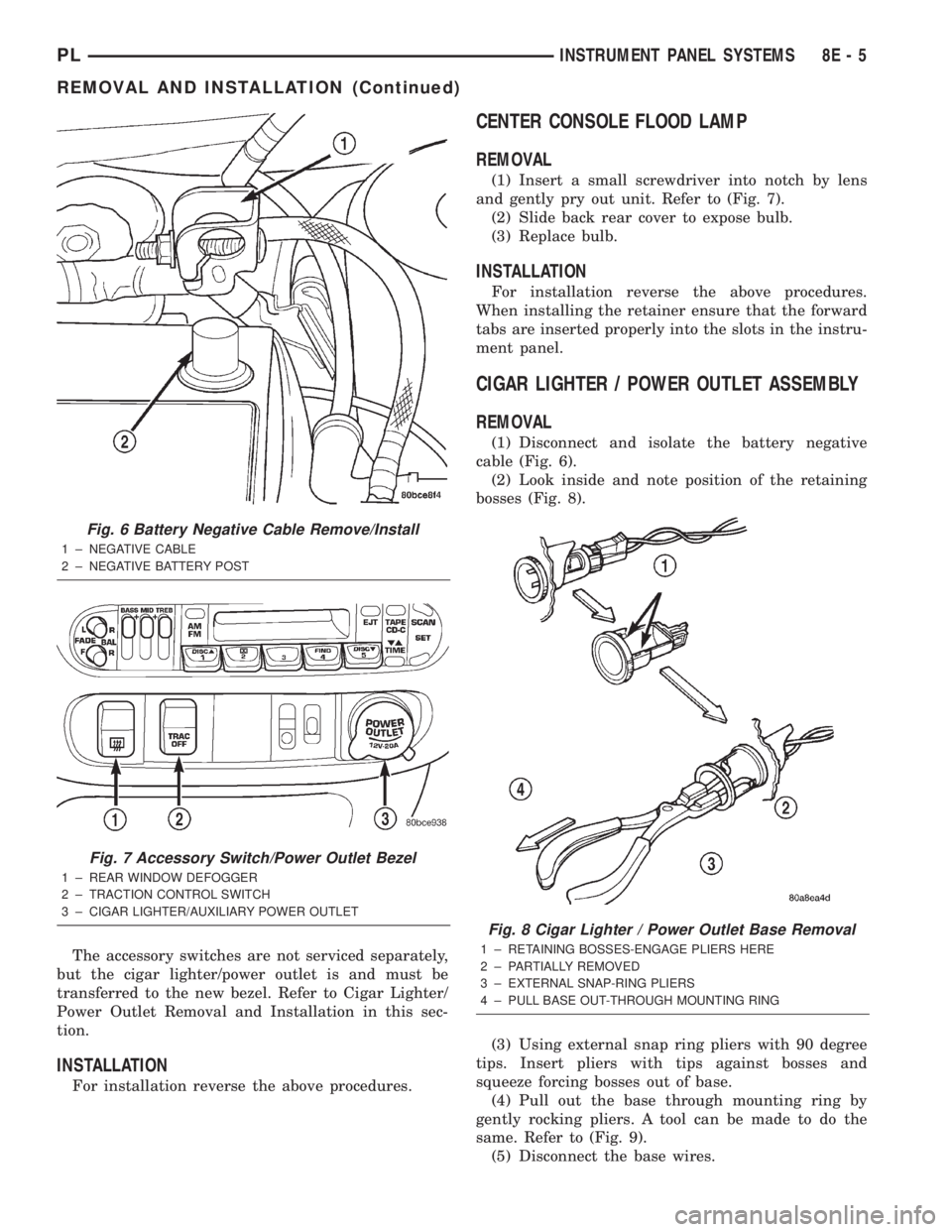
The accessory switches are not serviced separately,
but the cigar lighter/power outlet is and must be
transferred to the new bezel. Refer to Cigar Lighter/
Power Outlet Removal and Installation in this sec-
tion.
INSTALLATION
For installation reverse the above procedures.
CENTER CONSOLE FLOOD LAMP
REMOVAL
(1) Insert a small screwdriver into notch by lens
and gently pry out unit. Refer to (Fig. 7).
(2) Slide back rear cover to expose bulb.
(3) Replace bulb.
INSTALLATION
For installation reverse the above procedures.
When installing the retainer ensure that the forward
tabs are inserted properly into the slots in the instru-
ment panel.
CIGAR LIGHTER / POWER OUTLET ASSEMBLY
REMOVAL
(1) Disconnect and isolate the battery negative
cable (Fig. 6).
(2) Look inside and note position of the retaining
bosses (Fig. 8).
(3) Using external snap ring pliers with 90 degree
tips. Insert pliers with tips against bosses and
squeeze forcing bosses out of base.
(4) Pull out the base through mounting ring by
gently rocking pliers. A tool can be made to do the
same. Refer to (Fig. 9).
(5) Disconnect the base wires.
Fig. 6 Battery Negative Cable Remove/Install
1 ± NEGATIVE CABLE
2 ± NEGATIVE BATTERY POST
Fig. 7 Accessory Switch/Power Outlet Bezel
1 ± REAR WINDOW DEFOGGER
2 ± TRACTION CONTROL SWITCH
3 ± CIGAR LIGHTER/AUXILIARY POWER OUTLET
Fig. 8 Cigar Lighter / Power Outlet Base Removal
1 ± RETAINING BOSSES-ENGAGE PLIERS HERE
2 ± PARTIALLY REMOVED
3 ± EXTERNAL SNAP-RING PLIERS
4 ± PULL BASE OUT-THROUGH MOUNTING RING
PLINSTRUMENT PANEL SYSTEMS 8E - 5
REMOVAL AND INSTALLATION (Continued)
Page 357 of 1285
DIAGNOSIS AND TESTING
GRID LINES
The horizontal grid lines and vertical bus bar lines
printed and fired on the inside surface of rear win-
dow glass (Fig. 5) comprise an electrical parallel cir-
cuit. The electrically conductive lines are composed of
a silver-ceramic material which when fired on glass
becomes bonded to the glass and is highly resistant
to abrasion. It is possible however, that a break may
occur in an individual grid line resulting in no cur-
rent flow through the line. To detect breaks in grid
lines the following procedure is required:
(1) Turn ignition ON and turn control switch to
ON. The LED should come on.
(2) Using a DC voltmeter with 0-15 volt range,
contact terminal (B) with the negative lead of the
voltmeter. With the positive lead of the voltmeter,
contact terminal (A) (Fig. 5). The voltmeter should
read 10-14 volts. A lower voltage reading indicates a
poor connection in the feed or the ground circuit.
(3) With the negative lead of the voltmeter, contact
a good body ground point. The voltage reading should
not change.
(4) Connect the negative lead of the voltmeter to
terminal (B) and touch each grid line at Mid-Point
with the positive lead. A reading of:
²Approximately 6 volts indicates the line is OK.
²0 volts indicates a break in line between Mid-
Point (C) and terminal (A).
²10-14 volts indicates a break between Mid-Point
(C) and terminal (B).
Move the lead toward the break and voltage will
change as soon as the break is crossed. Refer to (Fig.
5).
REAR WINDOW DEFOGGER SWITCH
The rear window defogger switch may be tested in
the vehicle or out of the vehicle, on the bench.
IN-VEHICLE TESTING
(1) Remove the switch from the instrument panel
but leave the switch connected, refer to Group 8E-In-
strument Panel and Systems, Auxiliary Switch Bezel
Removal and Installation.
(2) Turn the ignition switch ON.
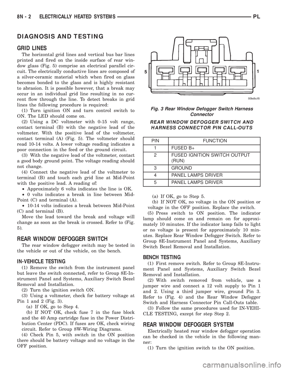
(3) Using a voltmeter, check for battery voltage at
Pin 1 and 2 (Fig. 3).
(a) If OK, go to Step 4.
(b) If NOT OK, check fuse 7 in the fuse block
and the 40 Amp cartridge fuse in the Power Distri-
bution Center (PDC). If fuses are OK, check wiring
circuit. Refer to Group 8W-Wiring Diagrams.
(4) Check Pin 5, with switch in the ON position
there should be battery voltage and no voltage in the
OFF position.(a) If OK, go to Step 5.
(b) If NOT OK, no voltage in the ON position or
voltage in the OFF position. Replace the switch.
(5) Press switch to ON position. The indicator
lamp should come on and remain on for approxi-
mately 10 minutes. If the indicator lamp fails to light
or no voltage is present for approximately 10 min-
utes. Replace Rear Window Defogger Switch. Refer to
Group 8E-Instrument Panel and Systems, Auxiliary
Switch Bezel Removal and Installation.
BENCH TESTING
(1) First remove switch. Refer to Group 8E-Instru-
ment Panel and Systems, Auxiliary Switch Bezel
Removal and Installation.
(2) With switch removed from vehicle, use a
jumper wire and connect a 12 volt supply to Pin 1
and 2. Using a third jumper wire, ground Pin 3.
Refer to (Fig. 4) and the Rear Window Defogger
Switch and Harness Connector Pin Call-Outs table.
(3) Follow the same procedures used for IN-VEHI-
CLE TESTING, except for step Step 2.
REAR WINDOW DEFOGGER SYSTEM
Electrically heated rear window defogger operation
can be checked in the vehicle in the following man-
ner:
(1) Turn the ignition switch to the ON position.
Fig. 3 Rear Window Defogger Switch Harness
Connector
REAR WINDOW DEFOGGER SWITCH AND
HARNESS CONNECTOR PIN CALL-OUTS
PIN FUNCTION
1 FUSED B+
2 FUSED IGNITION SWITCH OUTPUT
(RUN)
3 GROUND
4 PANEL LAMPS DRIVER
5 PANEL LAMPS DRIVER
8N - 2 ELECTRICALLY HEATED SYSTEMSPL
Page 831 of 1285
(3) Squeeze retainer tabs together and pull fuel
tube/quick-connect fitting assembly off of fuel tube
nipple. The retainer will remain on fuel tube.
INSTALLATION
CAUTION: Never install a quick-connect fitting
without the retainer being either on the fuel tube or
already in the quick-connect fitting. In either case,
ensure the retainer locks securely into the quick-
connect fitting by firmly pulling on fuel tube and fit-
ting to ensure it is secured.
(1) Using a clean lint free cloth, clean the fuel tube
nipple and retainer.
(2) Prior to connecting the fitting to the fuel tube,
coat the fuel tube nipple with clean 30 weight engine
oil.
(3) Push the quick-connect fitting over the fuel
tube until theretainer seats and a click is heard.
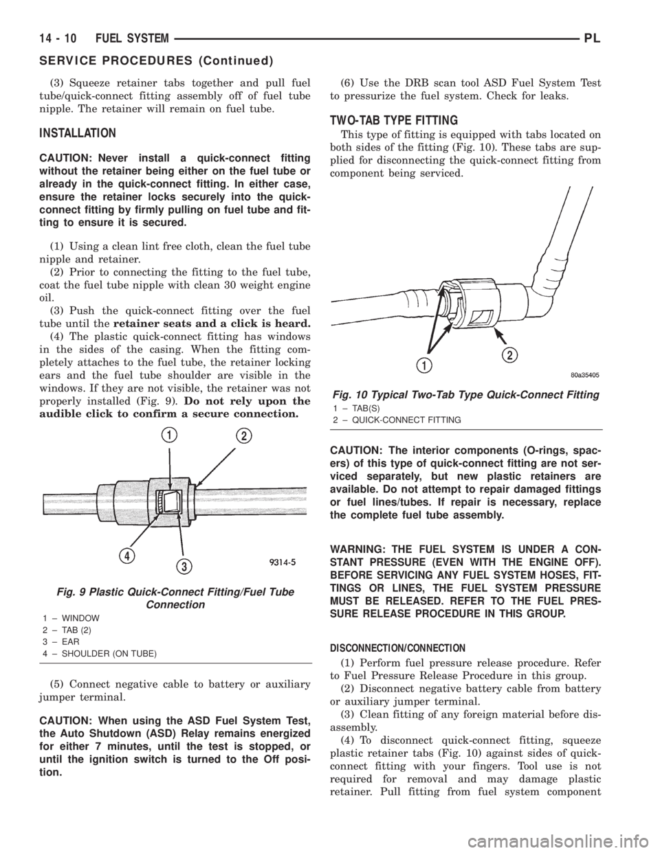
(4) The plastic quick-connect fitting has windows
in the sides of the casing. When the fitting com-
pletely attaches to the fuel tube, the retainer locking
ears and the fuel tube shoulder are visible in the
windows. If they are not visible, the retainer was not
properly installed (Fig. 9).Do not rely upon the
audible click to confirm a secure connection.
(5) Connect negative cable to battery or auxiliary
jumper terminal.
CAUTION: When using the ASD Fuel System Test,
the Auto Shutdown (ASD) Relay remains energized
for either 7 minutes, until the test is stopped, or
until the ignition switch is turned to the Off posi-
tion.(6) Use the DRB scan tool ASD Fuel System Test
to pressurize the fuel system. Check for leaks.
TWO-TAB TYPE FITTING
This type of fitting is equipped with tabs located on
both sides of the fitting (Fig. 10). These tabs are sup-
plied for disconnecting the quick-connect fitting from
component being serviced.
CAUTION: The interior components (O-rings, spac-
ers) of this type of quick-connect fitting are not ser-
viced separately, but new plastic retainers are
available. Do not attempt to repair damaged fittings
or fuel lines/tubes. If repair is necessary, replace
the complete fuel tube assembly.
WARNING:
THE FUEL SYSTEM IS UNDER A CON-
STANT PRESSURE (EVEN WITH THE ENGINE OFF).
BEFORE SERVICING ANY FUEL SYSTEM HOSES, FIT-
TINGS OR LINES, THE FUEL SYSTEM PRESSURE
MUST BE RELEASED. REFER TO THE FUEL PRES-
SURE RELEASE PROCEDURE IN THIS GROUP.
DISCONNECTION/CONNECTION
(1) Perform fuel pressure release procedure. Refer
to Fuel Pressure Release Procedure in this group.
(2) Disconnect negative battery cable from battery
or auxiliary jumper terminal.
(3) Clean fitting of any foreign material before dis-
assembly.
(4) To disconnect quick-connect fitting, squeeze
plastic retainer tabs (Fig. 10) against sides of quick-
connect fitting with your fingers. Tool use is not
required for removal and may damage plastic
retainer. Pull fitting from fuel system component
Fig. 9 Plastic Quick-Connect Fitting/Fuel Tube
Connection
1 ± WINDOW
2 ± TAB (2)
3 ± EAR
4 ± SHOULDER (ON TUBE)
Fig. 10 Typical Two-Tab Type Quick-Connect Fitting
1 ± TAB(S)
2 ± QUICK-CONNECT FITTING
14 - 10 FUEL SYSTEMPL
SERVICE PROCEDURES (Continued)
Page 832 of 1285
being serviced. The plastic retainer will remain on
component being serviced after fitting is discon-
nected. The O-rings and spacer will remain in quick-
connect fitting connector body.
(5) Inspect quick-connect fitting body and compo-
nent for damage. Replace as necessary.
CAUTION:
When the quick-connect fitting was dis-
connected, the plastic retainer will remain on the com-
ponent being serviced. If this retainer must be
removed, very carefully release the retainer from the
component with two small screwdrivers. After removal,
inspect the retainer for cracks or any damage.
(6) Prior to connecting quick-connect fitting to
component being serviced, check condition of fitting
and component. Clean parts with a lint-free cloth.
Lubricate with clean engine oil.
(7) Insert quick-connect fitting to component being
serviced and into plastic retainer. When a connection
is made, a click will be heard.
(8) Verify a locked condition by firmly pulling on
fuel tube and fitting (15-30 lbs.).
(9) Connect negative cable to battery or auxiliary
jumper terminal.
(10) Start engine and check for leaks.
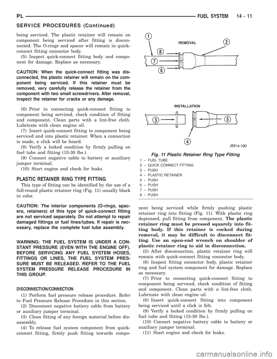
PLASTIC RETAINER RING TYPE FITTING
This type of fitting can be identified by the use of a
full-round plastic retainer ring (Fig. 11) usually black
in color.
CAUTION: The interior components (O-rings, spac-
ers, retainers) of this type of quick-connect fitting
are not serviced separately. Do not attempt to repair
damaged fittings or fuel lines/tubes. If repair is nec-
essary, replace the complete fuel tube assembly.
WARNING: THE FUEL SYSTEM IS UNDER A CON-
STANT PRESSURE (EVEN WITH THE ENGINE OFF).
BEFORE SERVICING ANY FUEL SYSTEM HOSES,
FITTINGS OR LINES, THE FUEL SYSTEM PRES-
SURE MUST BE RELEASED. REFER TO THE FUEL
SYSTEM PRESSURE RELEASE PROCEDURE IN
THIS GROUP.
DISCONNECTION/CONNECTION
(1) Perform fuel pressure release procedure. Refer
to Fuel Pressure Release Procedure in this section.
(2) Disconnect negative battery cable from battery
or auxiliary jumper terminal.
(3) Clean fitting of any foreign material before dis-
assembly.
(4) To release fuel system component from quick-
connect fitting, firmly push fitting towards compo-nent being serviced while firmly pushing plastic
retainer ring into fitting (Fig. 11). With plastic ring
depressed, pull fitting from component.The plastic
retainer ring must be pressed squarely into fit-
ting body. If this retainer is cocked during
removal, it may be difficult to disconnect fit-
ting. Use an open-end wrench on shoulder of
plastic retainer ring to aid in disconnection.
(5) After disconnection, plastic retainer ring will
remain with quick-connect fitting connector body.
(6) Inspect fitting connector body, plastic retainer
ring and fuel system component for damage. Replace
as necessary.
(7) Prior to connecting quick-connect fitting to
component being serviced, check condition of fitting
and component. Clean parts with a lint-free cloth.
Lubricate with clean engine oil.
(8) Insert quick-connect fitting into component
being serviced until a click is felt.
(9) Verify a locked condition by firmly pulling on
fuel tube and fitting (15-30 lbs.).
(10) Connect negative battery cable to battery or
auxiliary jumper terminal.
(11) Start engine and check for leaks.
Fig. 11 Plastic Retainer Ring Type Fitting
1 ± FUEL TUBE
2 ± QUICK CONNECT FITTING
3 ± PUSH
4 ± PLASTIC RETAINER
5 ± PUSH
6 ± PUSH
7 ± PUSH
8 ± PUSH
PLFUEL SYSTEM 14 - 11
SERVICE PROCEDURES (Continued)
Page 1100 of 1285
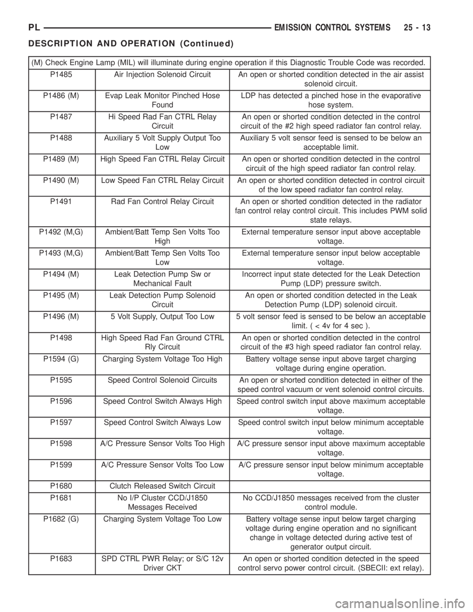
(M) Check Engine Lamp (MIL) will illuminate during engine operation if this Diagnostic Trouble Code was recorded.
P1485 Air Injection Solenoid Circuit An open or shorted condition detected in the air assist
solenoid circuit.
P1486 (M) Evap Leak Monitor Pinched Hose
FoundLDP has detected a pinched hose in the evaporative
hose system.
P1487 Hi Speed Rad Fan CTRL Relay
CircuitAn open or shorted condition detected in the control
circuit of the #2 high speed radiator fan control relay.
P1488 Auxiliary 5 Volt Supply Output Too
LowAuxiliary 5 volt sensor feed is sensed to be below an
acceptable limit.
P1489 (M) High Speed Fan CTRL Relay Circuit An open or shorted condition detected in the control
circuit of the high speed radiator fan control relay.
P1490 (M) Low Speed Fan CTRL Relay Circuit An open or shorted condition detected in control circuit
of the low speed radiator fan control relay.
P1491 Rad Fan Control Relay Circuit An open or shorted condition detected in the radiator
fan control relay control circuit. This includes PWM solid
state relays.
P1492 (M,G) Ambient/Batt Temp Sen Volts Too
HighExternal temperature sensor input above acceptable
voltage.
P1493 (M,G) Ambient/Batt Temp Sen Volts Too
LowExternal temperature sensor input below acceptable
voltage.
P1494 (M) Leak Detection Pump Sw or
Mechanical FaultIncorrect input state detected for the Leak Detection
Pump (LDP) pressure switch.
P1495 (M) Leak Detection Pump Solenoid
CircuitAn open or shorted condition detected in the Leak
Detection Pump (LDP) solenoid circuit.
P1496 (M) 5 Volt Supply, Output Too Low 5 volt sensor feed is sensed to be below an acceptable
limit.(<4vfor4sec).
P1498 High Speed Rad Fan Ground CTRL
Rly CircuitAn open or shorted condition detected in the control
circuit of the #3 high speed radiator fan control relay.
P1594 (G) Charging System Voltage Too High Battery voltage sense input above target charging
voltage during engine operation.
P1595 Speed Control Solenoid Circuits An open or shorted condition detected in either of the
speed control vacuum or vent solenoid control circuits.
P1596 Speed Control Switch Always High Speed control switch input above maximum acceptable
voltage.
P1597 Speed Control Switch Always Low Speed control switch input below minimum acceptable
voltage.
P1598 A/C Pressure Sensor Volts Too High A/C pressure sensor input above maximum acceptable
voltage.
P1599 A/C Pressure Sensor Volts Too Low A/C pressure sensor input below minimum acceptable
voltage.
P1680 Clutch Released Switch Circuit
P1681 No I/P Cluster CCD/J1850
Messages ReceivedNo CCD/J1850 messages received from the cluster
control module.
P1682 (G) Charging System Voltage Too Low Battery voltage sense input below target charging
voltage during engine operation and no significant
change in voltage detected during active test of
generator output circuit.
P1683 SPD CTRL PWR Relay; or S/C 12v
Driver CKTAn open or shorted condition detected in the speed
control servo power control circuit. (SBECII: ext relay).
PLEMISSION CONTROL SYSTEMS 25 - 13
DESCRIPTION AND OPERATION (Continued)