buttons DODGE NEON 2000 Service Repair Manual
[x] Cancel search | Manufacturer: DODGE, Model Year: 2000, Model line: NEON, Model: DODGE NEON 2000Pages: 1285, PDF Size: 29.42 MB
Page 286 of 1285

VEHICLE SPEED CONTROL SYSTEM
TABLE OF CONTENTS
page page
DESCRIPTION AND OPERATION
SPEED CONTROL SYSTEM.................1
SPEED CONTROL SERVO-PCM OUTPUT.......2
SPEED CONTROL SWITCHESÐPCM INPUT....2
STOP LAMP SWITCH......................3
SERVO CABLE...........................3
VACUUM RESERVOIR.....................3VEHICLE SPEED SENSOR..................3
REMOVAL AND INSTALLATION
SPEED CONTROL SERVO...................3
SPEED CONTROL SWITCH..................4
SPEED CONTROL SERVO CABLE.............4
VACUUM RESERVOIR.....................5
DESCRIPTION AND OPERATION
SPEED CONTROL SYSTEM
OPERATION
The speed control system is electronically con-
trolled and vacuum operated. The electronic control
is integrated into the Powertrain Control Module
which is located in the engine compartment. The con-
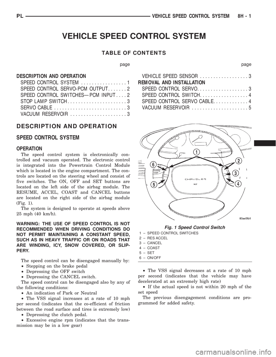
trols are located on the steering wheel and consist of
five switches. The ON, OFF and SET buttons are
located on the left side of the airbag module. The
RESUME, ACCEL, COAST and CANCEL buttons
are located on the right side of the airbag module
(Fig. 1).
The system is designed to operate at speeds above
25 mph (40 km/h).
WARNING: THE USE OF SPEED CONTROL IS NOT
RECOMMENDED WHEN DRIVING CONDITIONS DO
NOT PERMIT MAINTAINING A CONSTANT SPEED,
SUCH AS IN HEAVY TRAFFIC OR ON ROADS THAT
ARE WINDING, ICY, SNOW COVERED, OR SLIP-
PERY.
The speed control can be disengaged manually by:
²Stepping on the brake pedal
²Depressing the OFF switch
²Depressing the CANCEL switch.
The speed control can be disengaged also by any of
the following conditions:
²An indication of Park or Neutral
²The VSS signal increases at a rate of 10 mph
per second (indicates that the co-efficient of friction
between the road surface and tires is extremely low)
²Depressing the clutch pedal.
²Excessive engine rpm (indicates that the trans-
mission may be in a low gear)²The VSS signal decreases at a rate of 10 mph
per second (indicates that the vehicle may have
decelerated at an extremely high rate)
²If the actual speed is not within 20 mph of the
set speed
The previous disengagement conditions are pro-
grammed for added safety.
Fig. 1 Speed Control Switch
1 ± SPEED CONTROL SWITCHES
2 ± RES ACCEL
3 ± CANCEL
4 ± COAST
5 ± SET
6 ± ON/OFF
PLVEHICLE SPEED CONTROL SYSTEM 8H - 1
Page 368 of 1285

NOTE: The dealer must remove the module from
ªShip Modeº and place the RKE Module into either
the ªDealer Lotº storage or ªCustomer Usageº
modes of operation after receiving the vehicle from
the assembly plant. Refer to Group 8Q-Vehicle
Theft/Security Systems, Switching Operating
Modes/Configuring a New Module under Service
Procedures.
REMOTE KEYLESS ENTRY SYSTEM
The system allows locking and unlock of vehicle
door(s) and deck lid by remote control using a hand
held radio frequency (RF) transmitter. The vehicle
speed must be less than five miles per hour before
the deck lid can be unlatched with the transmitter.
The receiver may receive signals from four transmit-
ters. Each transmitter has its own code and the code
has been stored in memory. If the transmitter is
replaced or other transmitters are added, the code for
each unit must be learned.
REMOTE KEYLESS ENTRY TRANSMITTER
The transmitter has four buttons for operation
(Fig. 1). They are LOCK, UNLOCK, DECK LID
RELEASE, and PANIC.
²The UNLOCK button will unlock the driver door
and enable illuminated entry. Pushing and releasing
the button once will unlock the driver door. Pushing
and releasing the button two times within a five sec-
ond period will unlock all doors (double unlock acti-
vation enabled).
²Upon pressing the LOCK button, the horn will
sound a short chirp (if enabled) and flash the park
lamps to notify that the all door lock signal was
received and acted upon. Illuminated entry is can-
celled and the interior lamps are faded to off.
²Pushing and releasing the DECK LID
RELEASE button twice within a five second period
will actuate the decklid release solenoid, causing the
deck lid to be slightly ajar. If so desired, the decklid
may be set to release after one button push by the
dealer. For procedures on programming with the
DRB IIItscan tool, refer to the proper Body Diagnos-
tic Procedures Manual.
²Pushing the PANIC button will cause the panic
alarm to sound for three minutes, until the panic
button is pressed a second time, or until the vehicle
reaches a speed of 15 mph.
HORN CHIRP TOGGLE
Once the transmitters have been programmed, the
horn chirp can be enabled/disabled by sending the
horn chirp toggle operation code to the RKE Module.
This can be done using a DRB IIItscan tool or by
the customer. The horn chirp will enter the oppositestate of its current programmed state by receiving
this operation code. The RKE module is responsible
for keeping track of the horn chirp status.
DIAGNOSIS AND TESTING
REMOTE KEYLESS ENTRY MODULE
For procedures on diagnosing and testing the RKE
Module's RKE functions, refer to the proper Body
Diagnostic Procedures Manual.
DECKLID RELEASE SOLENOID
(1) Confirm operation of RKE transmitter(s) by
actuating Lock and Unlock functions.
(2) Confirm lead is connected to deck lid release
solenoid.
(3) Unplug lead, and use an ohmmeter to verify
continuity of connection between pin 2 of the harness
connector and ground. Refer to Group 8W-Wiring
Diagrams for Connector Pin-Outs.
(4) Connect test light to pin 1 of the harness con-
nector and actuate decklid release button on trans-
mitter. Refer to Group 8W-Wiring Diagrams for
Connector Pin-Outs.
(5) If test light comes on, the wiring circuit
between the RKE module and the solenoid is func-
tional, and the decklid solenoid should be replaced.
(6) If test light does not come on, refer to the
proper Body Diagnostic Procedures Manual for fur-
ther troubleshooting information.
SERVICE PROCEDURES
HORN CHIRP TOGGLE
The toggling of the horn chirp (between enabled
and disabled) can be performed with the use of the
DRB IIItscan tool or by the customer.
DRB lllTPROGRAMMING
When using the DRB IIItscan tool, select:
(1) ªTheft Alarmº
(2) ªVTSSº
(3) ªMiscellaneousº
and then the desired function.
CUSTOMER PROGRAMMING
Using a transmitter programmed to the RKE Mod-
ule, the status of the horn chirp may be toggled by
the customer.
NOTE: The RKE Module is responsible for keeping
track of the horn chirp status; thus this procedure
does not need to be repeated for each transmitter
programmed to the system.
PLPOWER LOCK SYSTEMS 8P - 5
DESCRIPTION AND OPERATION (Continued)
Page 369 of 1285

(1) With the ignition switch in RUN position, press
and hold the transmitter Unlock button (Fig. 1) for a
minimum of 4 seconds to a maximum of 10 seconds.
(2) Within the 4-10 second range, depress the
transmitter Lock button (Fig. 1). A chime will be
heard to indicate a successful toggle, at which time
the buttons may be released.
SWITCHING OPERATING MODES/
CONFIGURING A NEW MODULE
Refer to Group 8Q-Vehicle Theft/Security Systems,
Switching Operating Modes/Configuring A New Mod-
ule under Service Procedures.
TRANSMITTER PROGRAMMING
The Remote Keyless Entry transmitters can be
programmed with the use of the DRB IIItscan tool
or by the customer.
DRB lllTPROGRAMMING
When using the DRB IIItscan tool, select:
(1) ªTheft Alarmº
(2) ªVTSSº
(3) ªMiscellaneousº
and then the desired function.
CUSTOMER PROGRAMMING
For a customer to be able to program RKE trans-
mitters themselves, at least one RKE transmitter
must be programmed already. This procedure is to
add additional transmitters. If all transmitters are
lost, the DRB IIItscan tool must be used to program
the new transmitters.
(1) With the ignition switch in RUN position, press
and hold the transmitter Unlock button (Fig. 1) for a
minimum of 4 seconds to a maximum of 10 seconds.
(2) Within the 4-10 second range, depress the
transmitter Lock button (Fig. 1). A chime will be
heard to indicate successful toggle, at which time the
buttons may be released.
(3) Turn the ignition switch off to exist transmitter
programming mode.
REMOVAL AND INSTALLATION
DECK LID RELEASE SOLENOID
REMOVAL
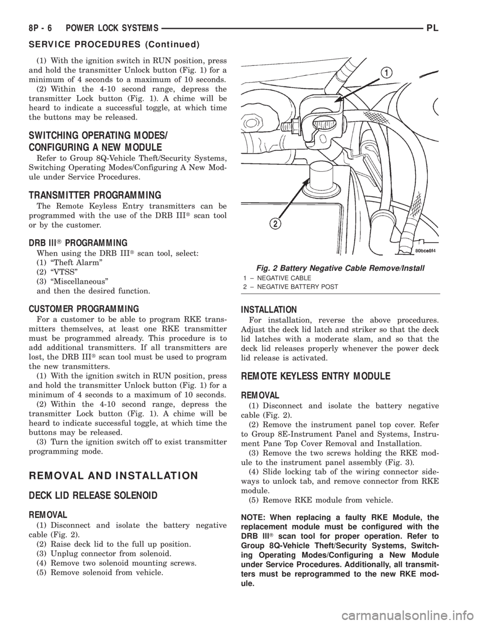
(1) Disconnect and isolate the battery negative
cable (Fig. 2).
(2) Raise deck lid to the full up position.
(3) Unplug connector from solenoid.
(4) Remove two solenoid mounting screws.
(5) Remove solenoid from vehicle.
INSTALLATION
For installation, reverse the above procedures.
Adjust the deck lid latch and striker so that the deck
lid latches with a moderate slam, and so that the
deck lid releases properly whenever the power deck
lid release is activated.
REMOTE KEYLESS ENTRY MODULE
REMOVAL
(1) Disconnect and isolate the battery negative
cable (Fig. 2).
(2) Remove the instrument panel top cover. Refer
to Group 8E-Instrument Panel and Systems, Instru-
ment Pane Top Cover Removal and Installation.
(3) Remove the two screws holding the RKE mod-
ule to the instrument panel assembly (Fig. 3).
(4) Slide locking tab of the wiring connector side-
ways to unlock tab, and remove connector from RKE
module.
(5) Remove RKE module from vehicle.
NOTE: When replacing a faulty RKE Module, the
replacement module must be configured with the
DRB lllTscan tool for proper operation. Refer to
Group 8Q-Vehicle Theft/Security Systems, Switch-
ing Operating Modes/Configuring a New Module
under Service Procedures. Additionally, all transmit-
ters must be reprogrammed to the new RKE mod-
ule.
Fig. 2 Battery Negative Cable Remove/Install
1 ± NEGATIVE CABLE
2 ± NEGATIVE BATTERY POST
8P - 6 POWER LOCK SYSTEMSPL
SERVICE PROCEDURES (Continued)