drain bolt DODGE NEON 2000 Service Repair Manual
[x] Cancel search | Manufacturer: DODGE, Model Year: 2000, Model line: NEON, Model: DODGE NEON 2000Pages: 1285, PDF Size: 29.42 MB
Page 111 of 1285
CAUTION: Use only a new brake booster input rod-
to-brake pedal retaining clip to ensure proper
retainment.
(4) Connect the power brake booster input rod-to-
brake pedal pin. Install a new retaining clip. Do not
use the old clip.
(5) Connect all previously removed vacuum hoses
to the vacuum check valve (Fig. 49).
(6) If the vehicle is equipped with ABS, install the
ICU mounting bracket on the frame rail using its
three bolts. Tighten the nuts to a torque of 23 N´m
(200 in. lbs.).
(7) If the vehicle is equipped with ABS, reinstall
the ICU. Refer to INTEGRATED CONTROL UNIT in
REMOVAL AND INSTALLATION within the
ANTILOCK BRAKE SYSTEM section of this service
manual group for the procedure.
(8) Install the master cylinder. For the master cyl-
inder without ABS removal and installation proce-
dure, refer to MASTER CYLINDER in this section of
this service manual group. For the master cylinder
with ABS removal and installation procedure, refer
to MASTER CYLINDER in the ANTILOCK BRAKE
SYSTEM section of this service manual group.
(9) Position the battery tray back in place. Install
the two bolts, then the two nuts mounting the bat-
tery tray to its bracket (Fig. 48). Tighten the two
bolts and nuts to a torque of 34 N´m (25 ft. lbs.).
(10) Reinstall the air cleaner box onto its grom-
meted alignment post (Fig. 48).
(11) Install the one nut and one bolt securing the
air cleaner box in place, then connect the wiring har-
ness connector at the air inlet sensor.
(12) Install the battery and clamp it in place.
(13) Connect the positive, then the negative
(ground) cable on the battery.
(14) Adjust the stop lamp switch as necessary.
Refer to STOP LAMP SWITCH in the ADJUST-
MENTS section of this group.
(15) Bleed the base brake system.
(16) Road test the vehicle to ensure proper opera-
tion of the brakes.
PROPORTIONING VALVE
NOTE: Before proceeding with this procedure,
review SERVICE WARNINGS AND CAUTIONS at the
beginning of REMOVAL AND INSTALLATION in this
section.
REMOVAL
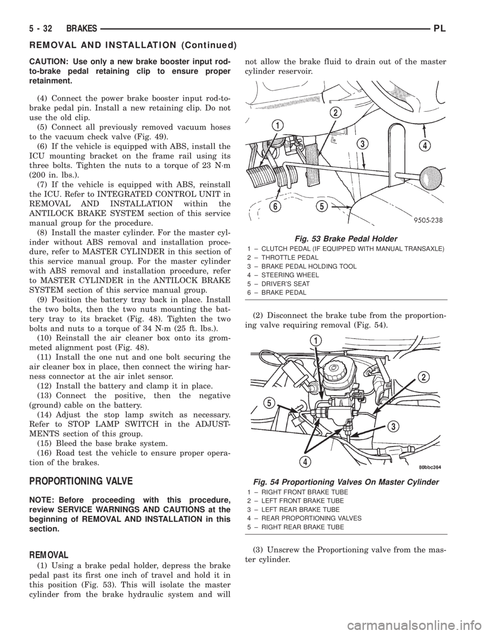
(1) Using a brake pedal holder, depress the brake
pedal past its first one inch of travel and hold it in
this position (Fig. 53). This will isolate the master
cylinder from the brake hydraulic system and willnot allow the brake fluid to drain out of the master
cylinder reservoir.
(2) Disconnect the brake tube from the proportion-
ing valve requiring removal (Fig. 54).
(3) Unscrew the Proportioning valve from the mas-
ter cylinder.
Fig. 53 Brake Pedal Holder
1 ± CLUTCH PEDAL (IF EQUIPPED WITH MANUAL TRANSAXLE)
2 ± THROTTLE PEDAL
3 ± BRAKE PEDAL HOLDING TOOL
4 ± STEERING WHEEL
5 ± DRIVER'S SEAT
6 ± BRAKE PEDAL
Fig. 54 Proportioning Valves On Master Cylinder
1 ± RIGHT FRONT BRAKE TUBE
2 ± LEFT FRONT BRAKE TUBE
3 ± LEFT REAR BRAKE TUBE
4 ± REAR PROPORTIONING VALVES
5 ± RIGHT REAR BRAKE TUBE
5 - 32 BRAKESPL
REMOVAL AND INSTALLATION (Continued)
Page 112 of 1285
INSTALLATION
(1) Lubricate the O-ring on the proportioning
valve. Make sure the O-ring on the proportioning
valve is new.
(2) Install the proportioning valve in its master
cylinder port. Tighten the proportioning valve to a
torque of 40 N´m (30 ft. lbs.).
(3) Connect the brake tube to the proportioning
valve (Fig. 54). Tighten the tube nut to a torque of 17
N´m (145 in. lbs.).
(4) Remove the brake pedal holder (Fig. 53).
(5) Bleed the affected brake line. See BASE
BRAKE BLEEDING in the SERVICE PROCE-
DURES section in this service manual group.
(6) Road test the vehicle to ensure proper opera-
tion of the brakes.
BRAKES TUBES AND HOSES
NOTE: Brake hoses for each brake are unique and
are not interchangeable.
Always use Mopartreplacement brake hoses to
ensure quality, correct length and superior fatigue
life. Care should be taken to make sure that the tube
and hose mating surfaces are clean and free from
nicks and burrs.
Use new copper seal washers on all connections
using banjo bolts and tighten all the fittings to their
specified torques.
Follow the procedures in the next three paragraphs
to reduce the potential for twisting the brake hose
during installation.
The flexible front hydraulic brake hose should
always be installed on the vehicle by first attaching
the banjo fitting to the disc brake caliper. Attach the
hose to the brake tubing before attaching it to the
front frame rail. Tighten all brake line fittings to the
specified torque.
On vehicles equipped with rear drum brakes,
loosely install the rear brake hose to the wheel cylin-
der first, then bolt the intermediate routing bracket
to the strut. Next, loosely install the hose to the steel
tube coming from the master cylinder. Attach the
hose bracket to the body. Finally, tighten the tube
nuts at each end of the brake hose.
On vehicles equipped with rear disc brakes, attach
the brake hose banjo fitting to the caliper first, then
loosely install the hose to the steel tube coming from
the master cylinder. Next, attach the brake hose
bracket to the body. Finally, tighten the tube nut at
the each of the end of the brake hose connecting to
the steel tube coming from the master cylinder.Only double wall 4.75 mm (3/16 in.) steel brake
line tubing with Nygal coating should be used for
replacement along with its special tube nuts. Care
must be taken when replacing brake tubing; to be
sure, use the proper bending and flaring tools, and
procedures to avoid kinking. Do not route the tubes
against sharp edges, moving components, or into hot
areas. All tubes should be properly attached with the
recommended retaining clips.
DISC BRAKE CALIPER (FRONT)
NOTE: Before proceeding with this procedure,
review SERVICE WARNINGS AND CAUTIONS at the
beginning of REMOVAL AND INSTALLATION in this
section.
REMOVAL
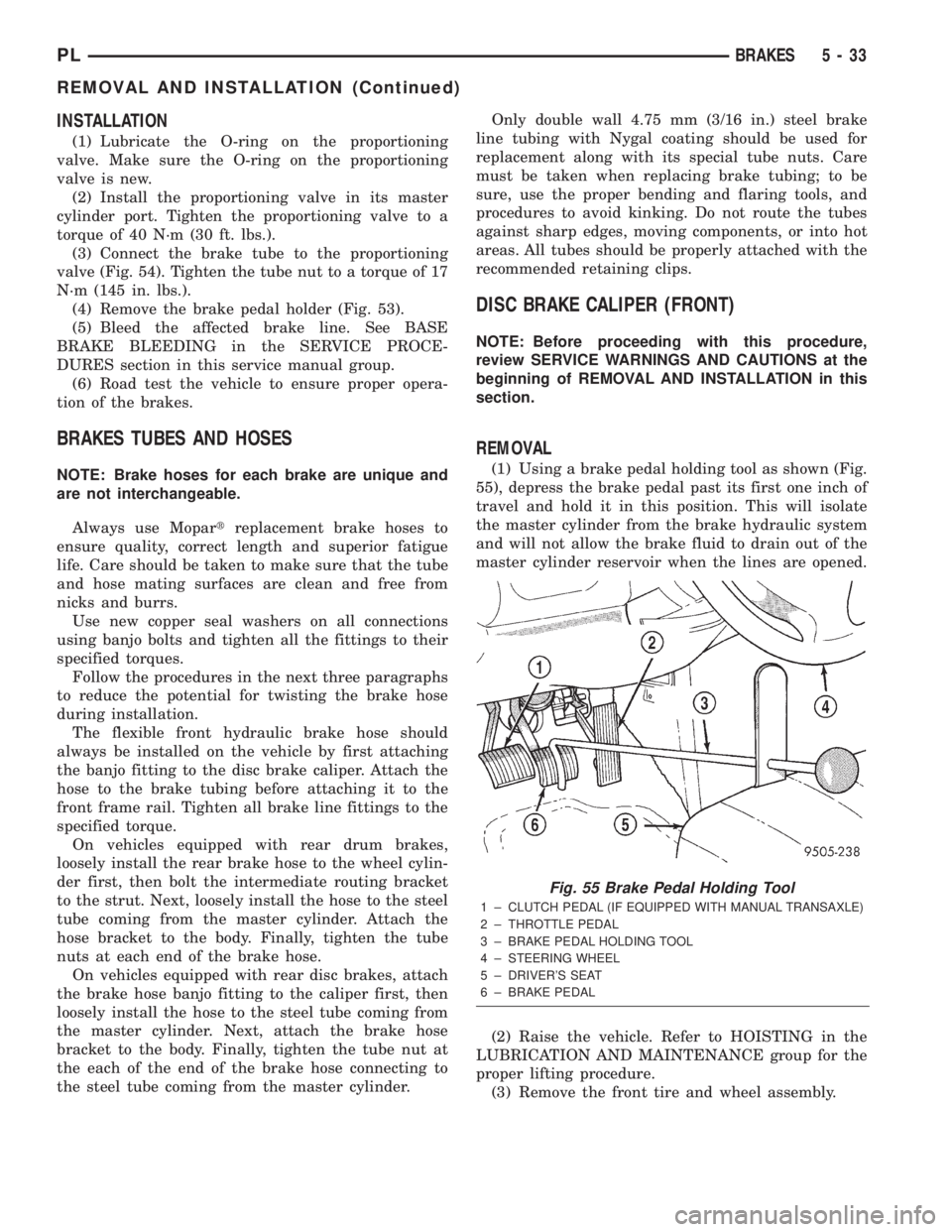
(1) Using a brake pedal holding tool as shown (Fig.
55), depress the brake pedal past its first one inch of
travel and hold it in this position. This will isolate
the master cylinder from the brake hydraulic system
and will not allow the brake fluid to drain out of the
master cylinder reservoir when the lines are opened.
(2) Raise the vehicle. Refer to HOISTING in the
LUBRICATION AND MAINTENANCE group for the
proper lifting procedure.
(3) Remove the front tire and wheel assembly.
Fig. 55 Brake Pedal Holding Tool
1 ± CLUTCH PEDAL (IF EQUIPPED WITH MANUAL TRANSAXLE)
2 ± THROTTLE PEDAL
3 ± BRAKE PEDAL HOLDING TOOL
4 ± STEERING WHEEL
5 ± DRIVER'S SEAT
6 ± BRAKE PEDAL
PLBRAKES 5 - 33
REMOVAL AND INSTALLATION (Continued)
Page 117 of 1285
DISC BRAKE CALIPER (REAR)
REMOVAL
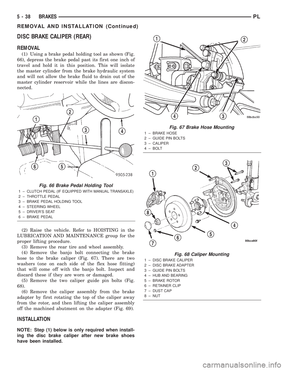
(1) Using a brake pedal holding tool as shown (Fig.
66), depress the brake pedal past its first one inch of
travel and hold it in this position. This will isolate
the master cylinder from the brake hydraulic system
and will not allow the brake fluid to drain out of the
master cylinder reservoir while the lines are discon-
nected.
(2) Raise the vehicle. Refer to HOISTING in the
LUBRICATION AND MAINTENANCE group for the
proper lifting procedure.
(3) Remove the rear tire and wheel assembly.
(4) Remove the banjo bolt connecting the brake
hose to the brake caliper (Fig. 67). There are two
washers (one on each side of the flex hose fitting)
that will come off with the banjo bolt. Inspect and
discard these if they are worn or damaged.
(5) Remove the two caliper guide pin bolts (Fig.
68).
(6) Remove the caliper assembly from the brake
adapter by first rotating the top of the caliper away
from the rotor, and then lifting the caliper assembly
off the machined abutment on the adapter (Fig. 69).
INSTALLATION
NOTE: Step (1) below is only required when install-
ing the disc brake caliper after new brake shoes
have been installed.
Fig. 66 Brake Pedal Holding Tool
1 ± CLUTCH PEDAL (IF EQUIPPED WITH MANUAL TRANSAXLE)
2 ± THROTTLE PEDAL
3 ± BRAKE PEDAL HOLDING TOOL
4 ± STEERING WHEEL
5 ± DRIVER'S SEAT
6 ± BRAKE PEDAL
Fig. 67 Brake Hose Mounting
1 ± BRAKE HOSE
2 ± GUIDE PIN BOLTS
3 ± CALIPER
4 ± BOLT
Fig. 68 Caliper Mounting
1 ± DISC BRAKE CALIPER
2 ± DISC BRAKE ADAPTER
3 ± GUIDE PIN BOLTS
4 ± HUB AND BEARING
5 ± BRAKE ROTOR
6 ± RETAINER CLIP
7 ± DUST CAP
8 ± NUT
5 - 38 BRAKESPL
REMOVAL AND INSTALLATION (Continued)
Page 121 of 1285
REMOVAL
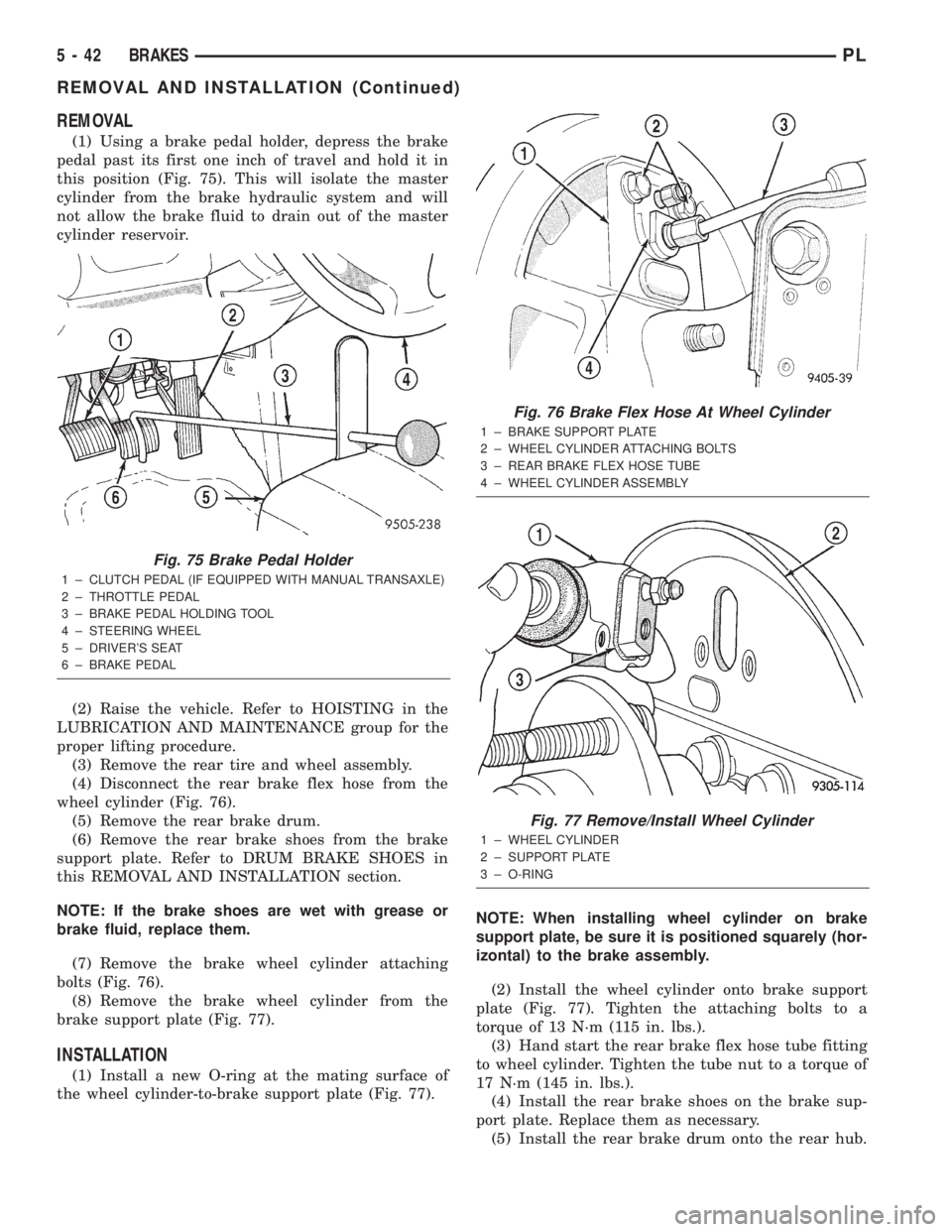
(1) Using a brake pedal holder, depress the brake
pedal past its first one inch of travel and hold it in
this position (Fig. 75). This will isolate the master
cylinder from the brake hydraulic system and will
not allow the brake fluid to drain out of the master
cylinder reservoir.
(2) Raise the vehicle. Refer to HOISTING in the
LUBRICATION AND MAINTENANCE group for the
proper lifting procedure.
(3) Remove the rear tire and wheel assembly.
(4) Disconnect the rear brake flex hose from the
wheel cylinder (Fig. 76).
(5) Remove the rear brake drum.
(6) Remove the rear brake shoes from the brake
support plate. Refer to DRUM BRAKE SHOES in
this REMOVAL AND INSTALLATION section.
NOTE: If the brake shoes are wet with grease or
brake fluid, replace them.
(7) Remove the brake wheel cylinder attaching
bolts (Fig. 76).
(8) Remove the brake wheel cylinder from the
brake support plate (Fig. 77).
INSTALLATION
(1) Install a new O-ring at the mating surface of
the wheel cylinder-to-brake support plate (Fig. 77).NOTE: When installing wheel cylinder on brake
support plate, be sure it is positioned squarely (hor-
izontal) to the brake assembly.
(2) Install the wheel cylinder onto brake support
plate (Fig. 77). Tighten the attaching bolts to a
torque of 13 N´m (115 in. lbs.).
(3) Hand start the rear brake flex hose tube fitting
to wheel cylinder. Tighten the tube nut to a torque of
17 N´m (145 in. lbs.).
(4) Install the rear brake shoes on the brake sup-
port plate. Replace them as necessary.
(5) Install the rear brake drum onto the rear hub.
Fig. 75 Brake Pedal Holder
1 ± CLUTCH PEDAL (IF EQUIPPED WITH MANUAL TRANSAXLE)
2 ± THROTTLE PEDAL
3 ± BRAKE PEDAL HOLDING TOOL
4 ± STEERING WHEEL
5 ± DRIVER'S SEAT
6 ± BRAKE PEDAL
Fig. 76 Brake Flex Hose At Wheel Cylinder
1 ± BRAKE SUPPORT PLATE
2 ± WHEEL CYLINDER ATTACHING BOLTS
3 ± REAR BRAKE FLEX HOSE TUBE
4 ± WHEEL CYLINDER ASSEMBLY
Fig. 77 Remove/Install Wheel Cylinder
1 ± WHEEL CYLINDER
2 ± SUPPORT PLATE
3 ± O-RING
5 - 42 BRAKESPL
REMOVAL AND INSTALLATION (Continued)
Page 125 of 1285
(4) Remove the brake drum (Fig. 87).
NOTE: If the drum does not come off, further brake
clearance can be obtained by backing off the brake
automatic adjuster screw. Remove the rubber plug
from the top of brake support plate. Rotate the
automatic adjuster screw in an upward motion,
using a screwdriver.
INSTALLATION
NOTE: Before installing the drum, inspect the brake
shoe linings for wear, shoe alignment, and contam-
ination.
(1) Install the rear brake drum on rear hub and
bearing (Fig. 87).
(2) Install the tire and wheel assembly. Tighten
the wheel mounting nuts to a torque of 135 N´m (100
ft. lbs.).
(3) Adjust the rear brake shoes as necessary. Refer
to ADJUSTMENTS in this section of this service
manual group.
(4) Lower the vehicle.
DRUM BRAKE SHOE SUPPORT PLATE (REAR)
NOTE: Before proceeding with this procedure,
review SERVICE WARNINGS AND CAUTIONS at the
beginning of REMOVAL AND INSTALLATION in this
section.
REMOVAL
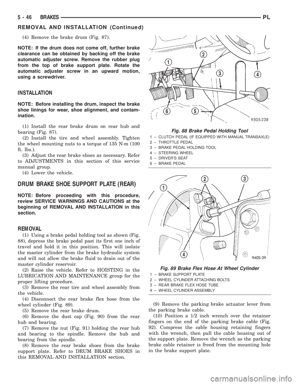
(1) Using a brake pedal holding tool as shown (Fig.
88), depress the brake pedal past its first one inch of
travel and hold it in this position. This will isolate
the master cylinder from the brake hydraulic system
and will not allow the brake fluid to drain out of the
master cylinder reservoir.
(2) Raise the vehicle. Refer to HOISTING in the
LUBRICATION AND MAINTENANCE group for the
proper lifting procedure.
(3) Remove the rear tire and wheel assembly from
the vehicle.
(4) Disconnect the rear brake flex hose from the
wheel cylinder (Fig. 89).
(5) Remove the rear brake drum.
(6) Remove the dust cap (Fig. 90) from the rear
hub and bearing.
(7) Remove the nut (Fig. 91) holding the rear hub
and bearing to the spindle. Remove the hub and
bearing from the spindle.
(8) Remove the rear brake shoes from the brake
support plate. Refer to DRUM BRAKE SHOES in
this REMOVAL AND INSTALLATION section.(9) Remove the parking brake actuator lever from
the parking brake cable.
(10) Position a 1/2 inch wrench over the retainer
fingers on the end of the parking brake cable (Fig.
92). Compress the cable housing retaining fingers
with the wrench, then pull the cable housing out of
the support plate. Remove the wrench as the parking
brake cable retainer is freed from the mounting hole
in the brake support plate.
Fig. 88 Brake Pedal Holding Tool
1 ± CLUTCH PEDAL (IF EQUIPPED WITH MANUAL TRANSAXLE)
2 ± THROTTLE PEDAL
3 ± BRAKE PEDAL HOLDING TOOL
4 ± STEERING WHEEL
5 ± DRIVER'S SEAT
6 ± BRAKE PEDAL
Fig. 89 Brake Flex Hose At Wheel Cylinder
1 ± BRAKE SUPPORT PLATE
2 ± WHEEL CYLINDER ATTACHING BOLTS
3 ± REAR BRAKE FLEX HOSE TUBE
4 ± WHEEL CYLINDER ASSEMBLY
5 - 46 BRAKESPL
REMOVAL AND INSTALLATION (Continued)
Page 158 of 1285
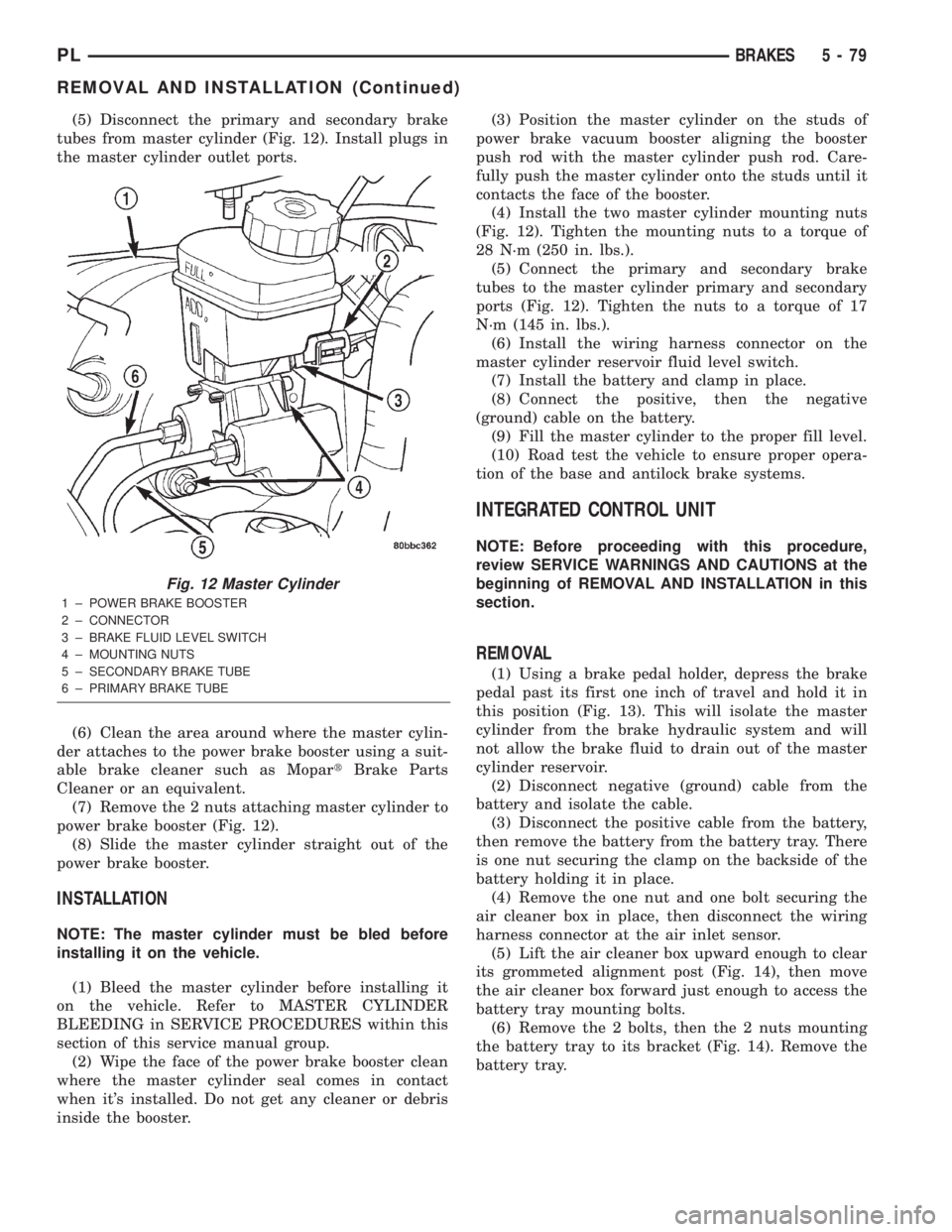
(5) Disconnect the primary and secondary brake
tubes from master cylinder (Fig. 12). Install plugs in
the master cylinder outlet ports.
(6) Clean the area around where the master cylin-
der attaches to the power brake booster using a suit-
able brake cleaner such as MopartBrake Parts
Cleaner or an equivalent.
(7) Remove the 2 nuts attaching master cylinder to
power brake booster (Fig. 12).
(8) Slide the master cylinder straight out of the
power brake booster.
INSTALLATION
NOTE: The master cylinder must be bled before
installing it on the vehicle.
(1) Bleed the master cylinder before installing it
on the vehicle. Refer to MASTER CYLINDER
BLEEDING in SERVICE PROCEDURES within this
section of this service manual group.
(2) Wipe the face of the power brake booster clean
where the master cylinder seal comes in contact
when it's installed. Do not get any cleaner or debris
inside the booster.(3) Position the master cylinder on the studs of
power brake vacuum booster aligning the booster
push rod with the master cylinder push rod. Care-
fully push the master cylinder onto the studs until it
contacts the face of the booster.
(4) Install the two master cylinder mounting nuts
(Fig. 12). Tighten the mounting nuts to a torque of
28 N´m (250 in. lbs.).
(5) Connect the primary and secondary brake
tubes to the master cylinder primary and secondary
ports (Fig. 12). Tighten the nuts to a torque of 17
N´m (145 in. lbs.).
(6) Install the wiring harness connector on the
master cylinder reservoir fluid level switch.
(7) Install the battery and clamp in place.
(8) Connect the positive, then the negative
(ground) cable on the battery.
(9) Fill the master cylinder to the proper fill level.
(10) Road test the vehicle to ensure proper opera-
tion of the base and antilock brake systems.
INTEGRATED CONTROL UNIT
NOTE: Before proceeding with this procedure,
review SERVICE WARNINGS AND CAUTIONS at the
beginning of REMOVAL AND INSTALLATION in this
section.
REMOVAL
(1) Using a brake pedal holder, depress the brake
pedal past its first one inch of travel and hold it in
this position (Fig. 13). This will isolate the master
cylinder from the brake hydraulic system and will
not allow the brake fluid to drain out of the master
cylinder reservoir.
(2) Disconnect negative (ground) cable from the
battery and isolate the cable.
(3) Disconnect the positive cable from the battery,
then remove the battery from the battery tray. There
is one nut securing the clamp on the backside of the
battery holding it in place.
(4) Remove the one nut and one bolt securing the
air cleaner box in place, then disconnect the wiring
harness connector at the air inlet sensor.
(5) Lift the air cleaner box upward enough to clear
its grommeted alignment post (Fig. 14), then move
the air cleaner box forward just enough to access the
battery tray mounting bolts.
(6) Remove the 2 bolts, then the 2 nuts mounting
the battery tray to its bracket (Fig. 14). Remove the
battery tray.
Fig. 12 Master Cylinder
1 ± POWER BRAKE BOOSTER
2 ± CONNECTOR
3 ± BRAKE FLUID LEVEL SWITCH
4 ± MOUNTING NUTS
5 ± SECONDARY BRAKE TUBE
6 ± PRIMARY BRAKE TUBE
PLBRAKES 5 - 79
REMOVAL AND INSTALLATION (Continued)
Page 174 of 1285
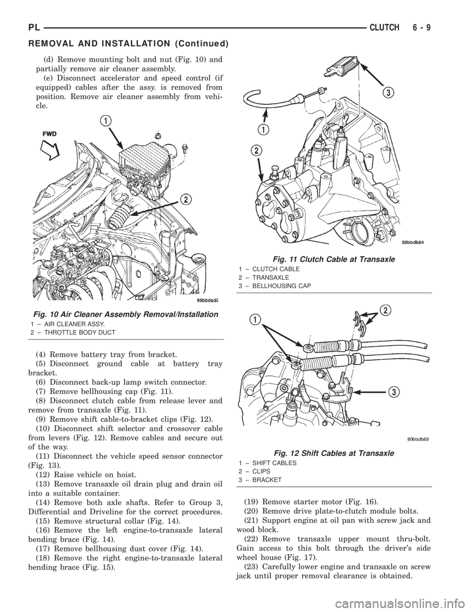
(d) Remove mounting bolt and nut (Fig. 10) and
partially remove air cleaner assembly.
(e) Disconnect accelerator and speed control (if
equipped) cables after the assy. is removed from
position. Remove air cleaner assembly from vehi-
cle.
(4) Remove battery tray from bracket.
(5) Disconnect ground cable at battery tray
bracket.
(6) Disconnect back-up lamp switch connector.
(7) Remove bellhousing cap (Fig. 11).
(8) Disconnect clutch cable from release lever and
remove from transaxle (Fig. 11).
(9) Remove shift cable-to-bracket clips (Fig. 12).
(10) Disconnect shift selector and crossover cable
from levers (Fig. 12). Remove cables and secure out
of the way.
(11) Disconnect the vehicle speed sensor connector
(Fig. 13).
(12) Raise vehicle on hoist.
(13) Remove transaxle oil drain plug and drain oil
into a suitable container.
(14) Remove both axle shafts. Refer to Group 3,
Differential and Driveline for the correct procedures.
(15) Remove structural collar (Fig. 14).
(16) Remove the left engine-to-transaxle lateral
bending brace (Fig. 14).
(17) Remove bellhousing dust cover (Fig. 14).
(18) Remove the right engine-to-transaxle lateral
bending brace (Fig. 15).(19) Remove starter motor (Fig. 16).
(20) Remove drive plate-to-clutch module bolts.
(21) Support engine at oil pan with screw jack and
wood block.
(22) Remove transaxle upper mount thru-bolt.
Gain access to this bolt through the driver's side
wheel house (Fig. 17).
(23) Carefully lower engine and transaxle on screw
jack until proper removal clearance is obtained.
Fig. 10 Air Cleaner Assembly Removal/Installation
1 ± AIR CLEANER ASSY.
2 ± THROTTLE BODY DUCTFWD
Fig. 11 Clutch Cable at Transaxle
1 ± CLUTCH CABLE
2 ± TRANSAXLE
3 ± BELLHOUSING CAP
Fig. 12 Shift Cables at Transaxle
1 ± SHIFT CABLES
2 ± CLIPS
3 ± BRACKET
PLCLUTCH 6 - 9
REMOVAL AND INSTALLATION (Continued)
Page 198 of 1285
COOLING SYSTEMÐDRAINING
NOTE: Drain, flush, and fill the cooling system at
the mileage or time intervals specified in Group 0,
Lubrication and Maintenance. If the solution is dirty,
rusty, or contains a considerable amount of sedi-
ment; clean and flush with a reliable cooling system
cleaner. Care should be taken in disposing of the
used engine coolant from your vehicle. Check gov-
ernmental regulations for disposal of used engine
coolant.
Without removing radiator pressure cap and
with system not under pressure:
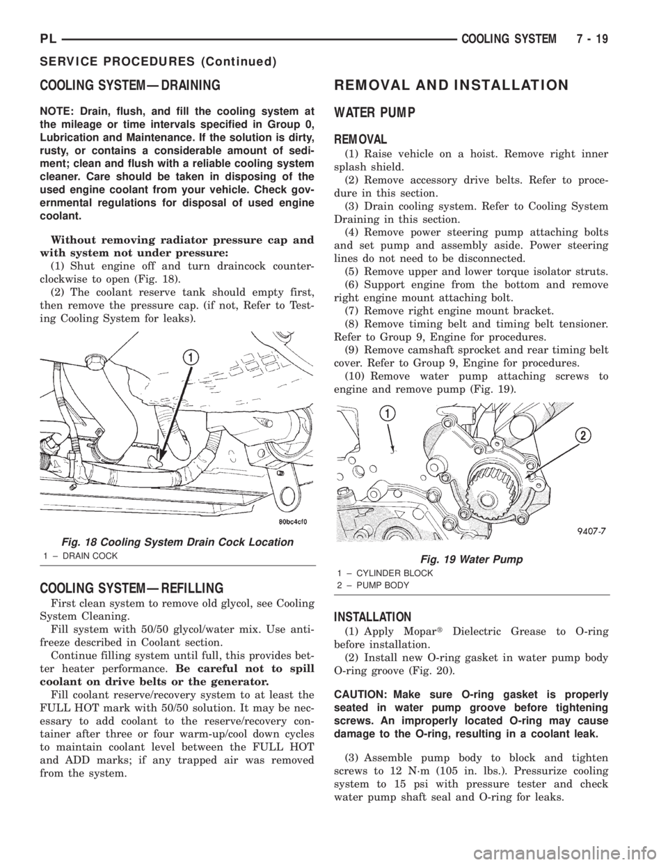
(1) Shut engine off and turn draincock counter-
clockwise to open (Fig. 18).
(2) The coolant reserve tank should empty first,
then remove the pressure cap. (if not, Refer to Test-
ing Cooling System for leaks).
COOLING SYSTEMÐREFILLING
First clean system to remove old glycol, see Cooling
System Cleaning.
Fill system with 50/50 glycol/water mix. Use anti-
freeze described in Coolant section.
Continue filling system until full, this provides bet-
ter heater performance.Be careful not to spill
coolant on drive belts or the generator.
Fill coolant reserve/recovery system to at least the
FULL HOT mark with 50/50 solution. It may be nec-
essary to add coolant to the reserve/recovery con-
tainer after three or four warm-up/cool down cycles
to maintain coolant level between the FULL HOT
and ADD marks; if any trapped air was removed
from the system.
REMOVAL AND INSTALLATION
WATER PUMP
REMOVAL
(1) Raise vehicle on a hoist. Remove right inner
splash shield.
(2) Remove accessory drive belts. Refer to proce-
dure in this section.
(3) Drain cooling system. Refer to Cooling System
Draining in this section.
(4) Remove power steering pump attaching bolts
and set pump and assembly aside. Power steering
lines do not need to be disconnected.
(5) Remove upper and lower torque isolator struts.
(6) Support engine from the bottom and remove
right engine mount attaching bolt.
(7) Remove right engine mount bracket.
(8) Remove timing belt and timing belt tensioner.
Refer to Group 9, Engine for procedures.
(9) Remove camshaft sprocket and rear timing belt
cover. Refer to Group 9, Engine for procedures.
(10) Remove water pump attaching screws to
engine and remove pump (Fig. 19).
INSTALLATION
(1) Apply MopartDielectric Grease to O-ring
before installation.
(2) Install new O-ring gasket in water pump body
O-ring groove (Fig. 20).
CAUTION: Make sure O-ring gasket is properly
seated in water pump groove before tightening
screws. An improperly located O-ring may cause
damage to the O-ring, resulting in a coolant leak.
(3) Assemble pump body to block and tighten
screws to 12 N´m (105 in. lbs.). Pressurize cooling
system to 15 psi with pressure tester and check
water pump shaft seal and O-ring for leaks.
Fig. 18 Cooling System Drain Cock Location
1 ± DRAIN COCKFig. 19 Water Pump
1 ± CYLINDER BLOCK
2 ± PUMP BODY
PLCOOLING SYSTEM 7 - 19
SERVICE PROCEDURES (Continued)
Page 200 of 1285
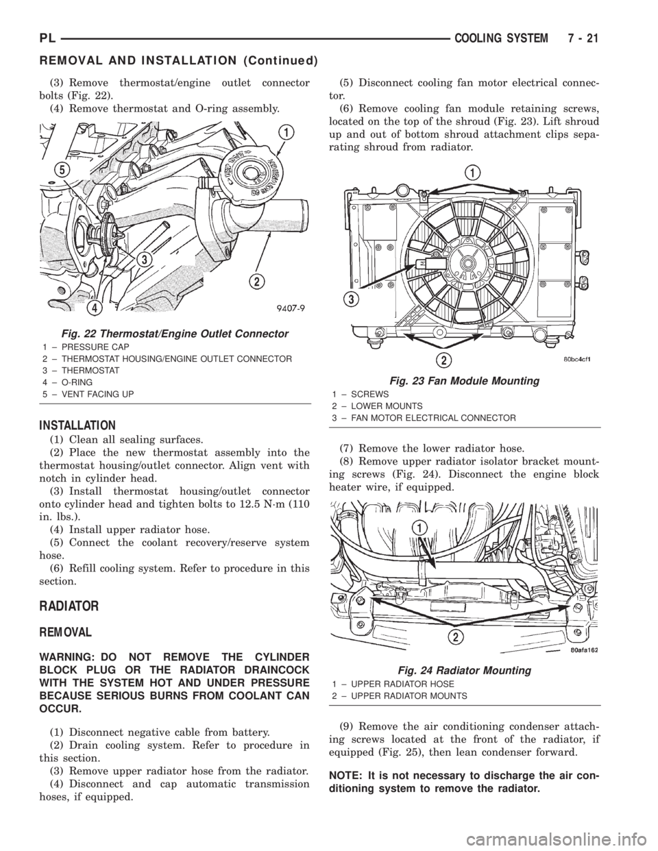
(3) Remove thermostat/engine outlet connector
bolts (Fig. 22).
(4) Remove thermostat and O-ring assembly.
INSTALLATION
(1) Clean all sealing surfaces.
(2) Place the new thermostat assembly into the
thermostat housing/outlet connector. Align vent with
notch in cylinder head.
(3) Install thermostat housing/outlet connector
onto cylinder head and tighten bolts to 12.5 N´m (110
in. lbs.).
(4) Install upper radiator hose.
(5) Connect the coolant recovery/reserve system
hose.
(6) Refill cooling system. Refer to procedure in this
section.
RADIATOR
REMOVAL
WARNING: DO NOT REMOVE THE CYLINDER
BLOCK PLUG OR THE RADIATOR DRAINCOCK
WITH THE SYSTEM HOT AND UNDER PRESSURE
BECAUSE SERIOUS BURNS FROM COOLANT CAN
OCCUR.
(1) Disconnect negative cable from battery.
(2) Drain cooling system. Refer to procedure in
this section.
(3) Remove upper radiator hose from the radiator.
(4) Disconnect and cap automatic transmission
hoses, if equipped.(5) Disconnect cooling fan motor electrical connec-
tor.
(6) Remove cooling fan module retaining screws,
located on the top of the shroud (Fig. 23). Lift shroud
up and out of bottom shroud attachment clips sepa-
rating shroud from radiator.
(7) Remove the lower radiator hose.
(8) Remove upper radiator isolator bracket mount-
ing screws (Fig. 24). Disconnect the engine block
heater wire, if equipped.
(9) Remove the air conditioning condenser attach-
ing screws located at the front of the radiator, if
equipped (Fig. 25), then lean condenser forward.
NOTE: It is not necessary to discharge the air con-
ditioning system to remove the radiator.
Fig. 22 Thermostat/Engine Outlet Connector
1 ± PRESSURE CAP
2 ± THERMOSTAT HOUSING/ENGINE OUTLET CONNECTOR
3 ± THERMOSTAT
4 ± O-RING
5 ± VENT FACING UP
Fig. 23 Fan Module Mounting
1 ± SCREWS
2 ± LOWER MOUNTS
3 ± FAN MOTOR ELECTRICAL CONNECTOR
Fig. 24 Radiator Mounting
1 ± UPPER RADIATOR HOSE
2 ± UPPER RADIATOR MOUNTS
PLCOOLING SYSTEM 7 - 21
REMOVAL AND INSTALLATION (Continued)
Page 748 of 1285
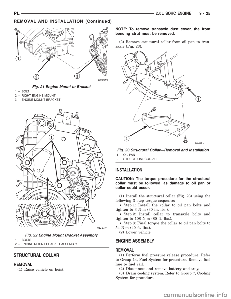
STRUCTURAL COLLAR
REMOVAL
(1) Raise vehicle on hoist.NOTE: To remove transaxle dust cover, the front
bending strut must be removed.
(2) Remove structural collar from oil pan to tran-
saxle (Fig. 23).
INSTALLATION
CAUTION: The torque procedure for the structural
collar must be followed, as damage to oil pan or
collar could occur.
(1) Install the structural collar (Fig. 23) using the
following 3 step torque sequence:
²Step 1: Install the collar to oil pan bolts and
tighten to 3 N´m (30 in. lbs.).
²Step 2: Install collar to transaxle bolts and
tighten to 108 N´m (80 ft. lbs.).
²Step 3: Final torque the collar to oil pan bolts to
54 N´m (40 ft. lbs.).
(2) Lower vehicle.
ENGINE ASSEMBLY
REMOVAL
(1) Perform fuel pressure release procedure. Refer
to Group 14, Fuel System for procedure. Remove fuel
line to fuel rail.
(2) Disconnect and remove battery and tray.
(3) Drain cooling system. Refer to Group 7, Cooling
System for procedure.
Fig. 21 Engine Mount to Bracket
1 ± BOLT
2 ± RIGHT ENGINE MOUNT
3 ± ENGINE MOUNT BRACKET
Fig. 22 Engine Mount Bracket Assembly
1 ± BOLTS
2 ± ENGINE MOUNT BRACKET ASSEMBLY
Fig. 23 Structural CollarÐRemoval and Installation
1 ± OIL PAN
2 ± STRUCTURAL COLLAR
PL2.0L SOHC ENGINE 9 - 25
REMOVAL AND INSTALLATION (Continued)