driver seat adjustment DODGE NEON 2000 Service Repair Manual
[x] Cancel search | Manufacturer: DODGE, Model Year: 2000, Model line: NEON, Model: DODGE NEON 2000Pages: 1285, PDF Size: 29.42 MB
Page 125 of 1285

(4) Remove the brake drum (Fig. 87).
NOTE: If the drum does not come off, further brake
clearance can be obtained by backing off the brake
automatic adjuster screw. Remove the rubber plug
from the top of brake support plate. Rotate the
automatic adjuster screw in an upward motion,
using a screwdriver.
INSTALLATION
NOTE: Before installing the drum, inspect the brake
shoe linings for wear, shoe alignment, and contam-
ination.
(1) Install the rear brake drum on rear hub and
bearing (Fig. 87).
(2) Install the tire and wheel assembly. Tighten
the wheel mounting nuts to a torque of 135 N´m (100
ft. lbs.).
(3) Adjust the rear brake shoes as necessary. Refer
to ADJUSTMENTS in this section of this service
manual group.
(4) Lower the vehicle.
DRUM BRAKE SHOE SUPPORT PLATE (REAR)
NOTE: Before proceeding with this procedure,
review SERVICE WARNINGS AND CAUTIONS at the
beginning of REMOVAL AND INSTALLATION in this
section.
REMOVAL
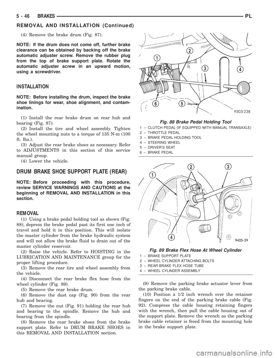
(1) Using a brake pedal holding tool as shown (Fig.
88), depress the brake pedal past its first one inch of
travel and hold it in this position. This will isolate
the master cylinder from the brake hydraulic system
and will not allow the brake fluid to drain out of the
master cylinder reservoir.
(2) Raise the vehicle. Refer to HOISTING in the
LUBRICATION AND MAINTENANCE group for the
proper lifting procedure.
(3) Remove the rear tire and wheel assembly from
the vehicle.
(4) Disconnect the rear brake flex hose from the
wheel cylinder (Fig. 89).
(5) Remove the rear brake drum.
(6) Remove the dust cap (Fig. 90) from the rear
hub and bearing.
(7) Remove the nut (Fig. 91) holding the rear hub
and bearing to the spindle. Remove the hub and
bearing from the spindle.
(8) Remove the rear brake shoes from the brake
support plate. Refer to DRUM BRAKE SHOES in
this REMOVAL AND INSTALLATION section.(9) Remove the parking brake actuator lever from
the parking brake cable.
(10) Position a 1/2 inch wrench over the retainer
fingers on the end of the parking brake cable (Fig.
92). Compress the cable housing retaining fingers
with the wrench, then pull the cable housing out of
the support plate. Remove the wrench as the parking
brake cable retainer is freed from the mounting hole
in the brake support plate.
Fig. 88 Brake Pedal Holding Tool
1 ± CLUTCH PEDAL (IF EQUIPPED WITH MANUAL TRANSAXLE)
2 ± THROTTLE PEDAL
3 ± BRAKE PEDAL HOLDING TOOL
4 ± STEERING WHEEL
5 ± DRIVER'S SEAT
6 ± BRAKE PEDAL
Fig. 89 Brake Flex Hose At Wheel Cylinder
1 ± BRAKE SUPPORT PLATE
2 ± WHEEL CYLINDER ATTACHING BOLTS
3 ± REAR BRAKE FLEX HOSE TUBE
4 ± WHEEL CYLINDER ASSEMBLY
5 - 46 BRAKESPL
REMOVAL AND INSTALLATION (Continued)