differential DODGE NEON 2000 Service Repair Manual
[x] Cancel search | Manufacturer: DODGE, Model Year: 2000, Model line: NEON, Model: DODGE NEON 2000Pages: 1285, PDF Size: 29.42 MB
Page 1 of 1285
GROUP TAB LOCATORINIntroductionINaIntroduction0Lubrication and Maintenance2Suspension3Differential and Driveline5Brakes6Clutch7Cooling8ABattery8BStarting8CCharging System8DIgnition System8EInstrument Panel and Systems8EaInstrument Panel and Systems8FAudio System8GHorns8HVehicle Speed Control System8JTurn Signal and Flashers8KWindshield Wipers and Washers8LLamps8LaLamps8MRestraint System8NElectrically Heated Systems8OPower Distribution Systems8PPower Door Locks8QImmobilizer System8SPower Windows8TPower Mirrors8TaPower Mirrors8UChime Warning/Reminder System8WWiring Diagrams - LHD and RHD9Engine11Exhaust System13Frame and Bumpers14Fuel System19Steering21Transaxle22Tires and Wheels23Body24Heating and Air Conditioning24aHeating and Air Conditioning25Emission Control Systems
Page 30 of 1285

lizer bar cushion retainer bolts a little to ease any
turning resistance.
(5) Remove the nut and pinch bolt clamping the
ball joint stud to the steering knuckle (Fig. 15).
CAUTION: After removing the steering knuckle
from the ball joint stud, do not pull outward on the
knuckle. Pulling the steering knuckle outward at
this point can separate the inner C/V joint on the
driveshaft. Refer to FRONT DRIVESHAFTS in the
DIFFERENTIAL AND DRIVELINE group for further
information.
NOTE: Use caution when separating the ball joint
stud from the steering knuckle, so the ball joint seal
does not get cut.
(6) Separate the ball joint stud from the steering
knuckle by prying down on lower control arm and up
against the ball joint boss on the steering knuckle
(Fig. 12).
(7) If the right lower control arm is being serviced,
remove the bolts mounting the engine torque strut in
place (Fig. 16), then remove the engine torque strut
from the vehicle.
(8) Remove the front pivot bolt attaching the lower
control arm to the front suspension crossmember
(Fig. 17). Remove the rear pivot bolt attaching the
lower control arm to the front suspension crossmem-
ber and frame rail. Remove the lower control arm
from the crossmember.
INSTALLATION
(1) Position the lower control arm into the cross-
member (Fig. 17). Install, but do not fully tighten,
the rear pivot bolt attaching the lower control arm to
the front suspension crossmember and frame rail.
Install the front pivot bolt attaching the lower con-
trol arm to the front suspension crossmember.
(2) Tighten the lower control arm rear pivot (and
suspension crossmember) bolt to a torque of 203 N´m
(150 ft. lbs.), then tighten the lower control arm front
pivot bolt to a torque of 163 N´m (120 ft. lbs.).
(3) Install the ball joint stud into the steering
knuckle aligning the bolt hole in the knuckle boss
Fig. 15 Ball Joint Bolt And Nut
1 ± NUT
2 ± BOLT
3 ± BALL JOINT
Fig. 16 Engine Torque Strut
1 ± MOUNTING BOLTS
2 ± ENGINE TORQUE ISOLATOR STRUT
3 ± FRONT SUSPENSION CROSSMEMBER
Fig. 17 Lower Control Arm Attaching Bolts
1 ± LOWER CONTROL ARM
2 ± FRONT BOLT
3 ± CROSSMEMBER
4 ± REAR BOLT
PLSUSPENSION 2 - 19
REMOVAL AND INSTALLATION (Continued)
Page 62 of 1285
DIFFERENTIAL AND DRIVELINE
TABLE OF CONTENTS
page page
DESCRIPTION AND OPERATION
FRONT DRIVESHAFTS.....................1
DIAGNOSIS AND TESTING
DRIVESHAFT DIAGNOSIS...................2
REMOVAL AND INSTALLATION
DRIVESHAFTS...........................3
DISASSEMBLY AND ASSEMBLY
DRIVESHAFT RECONDITION................7INNER TRIPOD JOINT SEAL BOOT...........7
OUTER C/V JOINT SEAL BOOT.............13
SPECIFICATIONS
TORQUE...............................17
SPECIAL TOOLS
DRIVESHAFT............................17
DESCRIPTION AND OPERATION
FRONT DRIVESHAFTS
Vehicles equipped with either an automatic or
manual transmission use an unequal±length drive-
shaft system.The system incorporates two driveshaft assemblies
(left and right) that consist of an inner and outer
constant velocity (CV) joint and a solid interconnect-
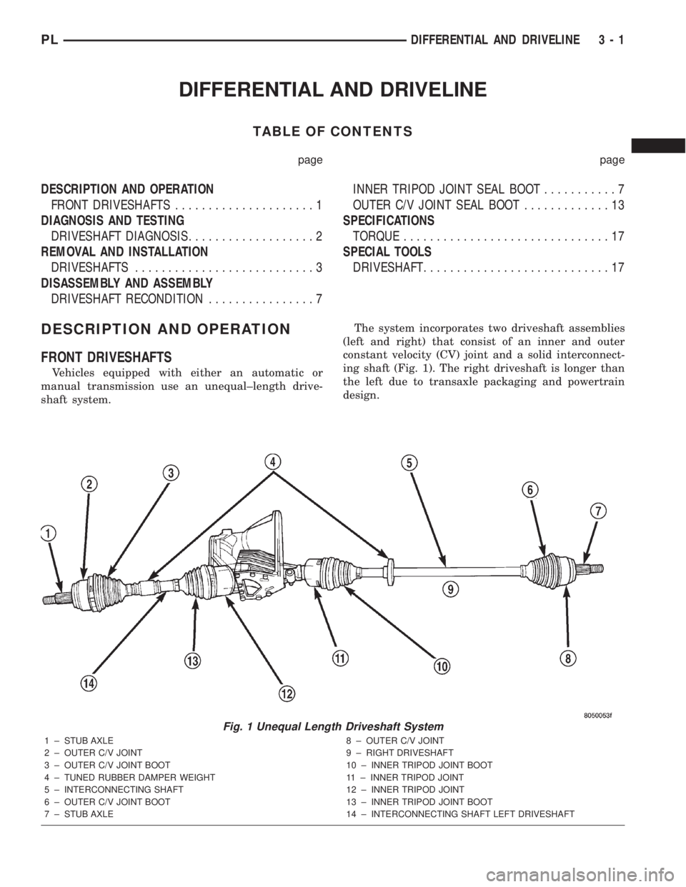
ing shaft (Fig. 1). The right driveshaft is longer than
the left due to transaxle packaging and powertrain
design.
Fig. 1 Unequal Length Driveshaft System
1 ± STUB AXLE
2 ± OUTER C/V JOINT
3 ± OUTER C/V JOINT BOOT
4 ± TUNED RUBBER DAMPER WEIGHT
5 ± INTERCONNECTING SHAFT
6 ± OUTER C/V JOINT BOOT
7 ± STUB AXLE8 ± OUTER C/V JOINT
9 ± RIGHT DRIVESHAFT
10 ± INNER TRIPOD JOINT BOOT
11 ± INNER TRIPOD JOINT
12 ± INNER TRIPOD JOINT
13 ± INNER TRIPOD JOINT BOOT
14 ± INTERCONNECTING SHAFT LEFT DRIVESHAFT
PLDIFFERENTIAL AND DRIVELINE 3 - 1
Page 63 of 1285
Driveshafts used on both the right and left sides of
the vehicle use a tuned rubber damper weight
mounted to the interconnecting shaft (Fig. 1). The
damper weight applications vary by which side of the
vehicle the driveshaft is located on and the transmis-
sion application of the vehicle. When replacing a
driveshaft, be sure the replacement driveshaft has
the same damper weight as the original.
Both driveshaft assemblies use the same type of
inner and outer joints. The inner joint of both drive-
shaft assemblies is a tripod joint, and the outer joint
of both driveshaft assemblies is a Rzeppa joint. Both
tripod joints and Rzeppa joints are true constant
velocity (C/V) joint assemblies. The inner tripod joint
allows for the changes in driveshaft length through
the jounce and rebound travel of the front suspen-
sion.
On vehicles equipped with ABS brakes, the outer
C/V joint is equipped with a tone wheel used to
determine vehicle speed for ABS brake operation.
The inner tripod joint of both driveshafts is splined
into the transaxle side gears. The inner tripod joints
are retained in the side gears of the transaxle using
a snap ring located in the stub shaft of the tripod
joint. The outer C/V joint has a stub shaft that is
splined into the wheel hub and retained by a single
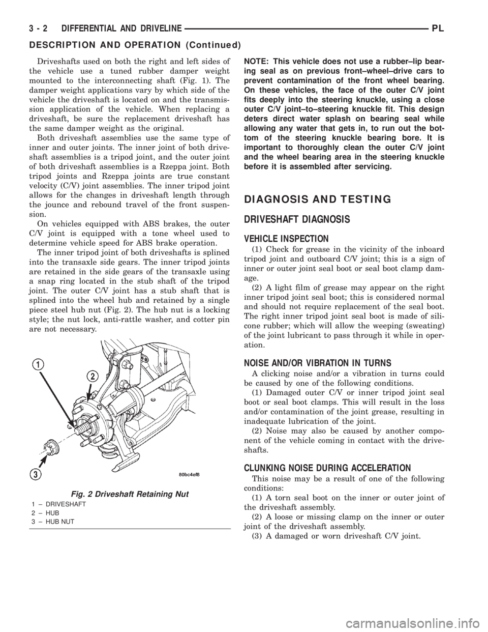
piece steel hub nut (Fig. 2). The hub nut is a locking
style; the nut lock, anti-rattle washer, and cotter pin
are not necessary.NOTE: This vehicle does not use a rubber±lip bear-
ing seal as on previous front±wheel±drive cars to
prevent contamination of the front wheel bearing.
On these vehicles, the face of the outer C/V joint
fits deeply into the steering knuckle, using a close
outer C/V joint±to±steering knuckle fit. This design
deters direct water splash on bearing seal while
allowing any water that gets in, to run out the bot-
tom of the steering knuckle bearing bore. It is
important to thoroughly clean the outer C/V joint
and the wheel bearing area in the steering knuckle
before it is assembled after servicing.
DIAGNOSIS AND TESTING
DRIVESHAFT DIAGNOSIS
VEHICLE INSPECTION
(1) Check for grease in the vicinity of the inboard
tripod joint and outboard C/V joint; this is a sign of
inner or outer joint seal boot or seal boot clamp dam-
age.
(2) A light film of grease may appear on the right
inner tripod joint seal boot; this is considered normal
and should not require replacement of the seal boot.
The right inner tripod joint seal boot is made of sili-
cone rubber; which will allow the weeping (sweating)
of the joint lubricant to pass through it while in oper-
ation.
NOISE AND/OR VIBRATION IN TURNS
A clicking noise and/or a vibration in turns could
be caused by one of the following conditions.
(1) Damaged outer C/V or inner tripod joint seal
boot or seal boot clamps. This will result in the loss
and/or contamination of the joint grease, resulting in
inadequate lubrication of the joint.
(2) Noise may also be caused by another compo-
nent of the vehicle coming in contact with the drive-
shafts.
CLUNKING NOISE DURING ACCELERATION
This noise may be a result of one of the following
conditions:
(1) A torn seal boot on the inner or outer joint of
the driveshaft assembly.
(2) A loose or missing clamp on the inner or outer
joint of the driveshaft assembly.
(3) A damaged or worn driveshaft C/V joint.
Fig. 2 Driveshaft Retaining Nut
1 ± DRIVESHAFT
2 ± HUB
3 ± HUB NUT
3 - 2 DIFFERENTIAL AND DRIVELINEPL
DESCRIPTION AND OPERATION (Continued)
Page 64 of 1285
SHUDDER OR VIBRATION DURING ACCELERATION
(1) A worn or damaged driveshaft inner tripod
joint.
(2) A sticking tripod joint spider assembly (inner
tripod joint only).
(3) Improper wheel alignment. See Wheel Align-
ment in this group for alignment checking and set-
ting procedures and specifications.
VIBRATION AT HIGHWAY SPEEDS
(1) Foreign material (mud, etc.) packed on the
backside of the wheel(s).
(2) Out of balance front tires or wheels. See Group
22, Wheels And Tires for the required balancing pro-
cedure.
(3) Improper tire and/or wheel runout. See Group
22, Wheels And Tires for the required runout check-
ing procedure.
REMOVAL AND INSTALLATION
DRIVESHAFTS
CAUTION: Boot sealing is vital to retain special
lubricants and to prevent foreign contaminants
from entering the C/V joint. Mishandling, such as
allowing the assemblies to dangle unsupported, or
pulling or pushing the ends can cut boots or dam-
age C/V joints. During removal and installation pro-
cedures, always support both ends of the driveshaft
to prevent damage.
REMOVAL
CAUTION: The driveshaft, when installed, acts as a
bolt and secures the front hub/bearing assembly. If
vehicle is to be supported or moved on its wheels
with a driveshaft removed, install a PROPER±SIZED
BOLT AND NUT through front hub. Tighten bolt and
nut to 203 N´m (150 ft. lbs.). This will ensure that
the hub bearing cannot loosen.
(1) Disconnect battery negative cable.
(2) Place transaxle in gated park.
(3) Raise vehicle on hoist.
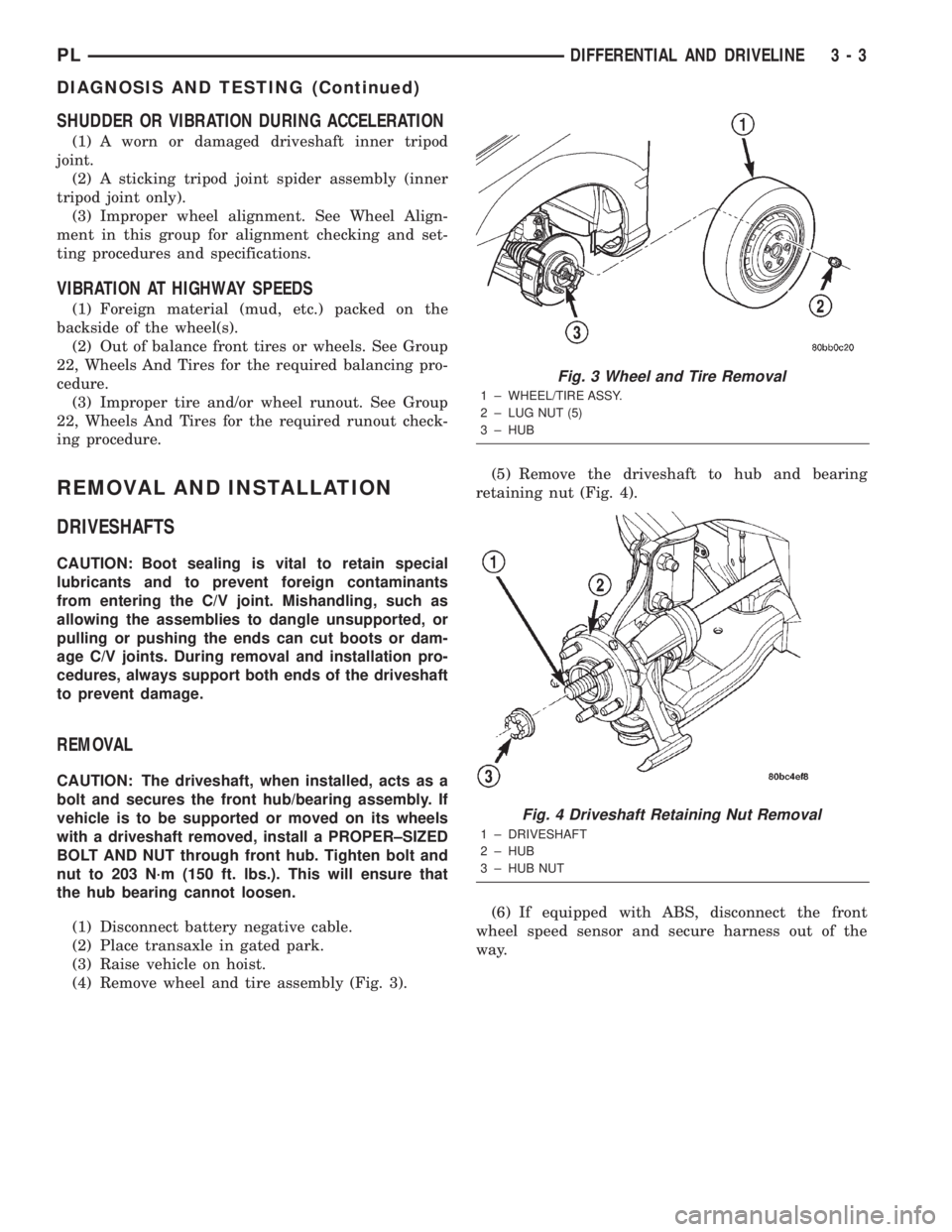
(4) Remove wheel and tire assembly (Fig. 3).(5) Remove the driveshaft to hub and bearing
retaining nut (Fig. 4).
(6) If equipped with ABS, disconnect the front
wheel speed sensor and secure harness out of the
way.
Fig. 3 Wheel and Tire Removal
1 ± WHEEL/TIRE ASSY.
2 ± LUG NUT (5)
3 ± HUB
Fig. 4 Driveshaft Retaining Nut Removal
1 ± DRIVESHAFT
2 ± HUB
3 ± HUB NUT
PLDIFFERENTIAL AND DRIVELINE 3 - 3
DIAGNOSIS AND TESTING (Continued)
Page 65 of 1285
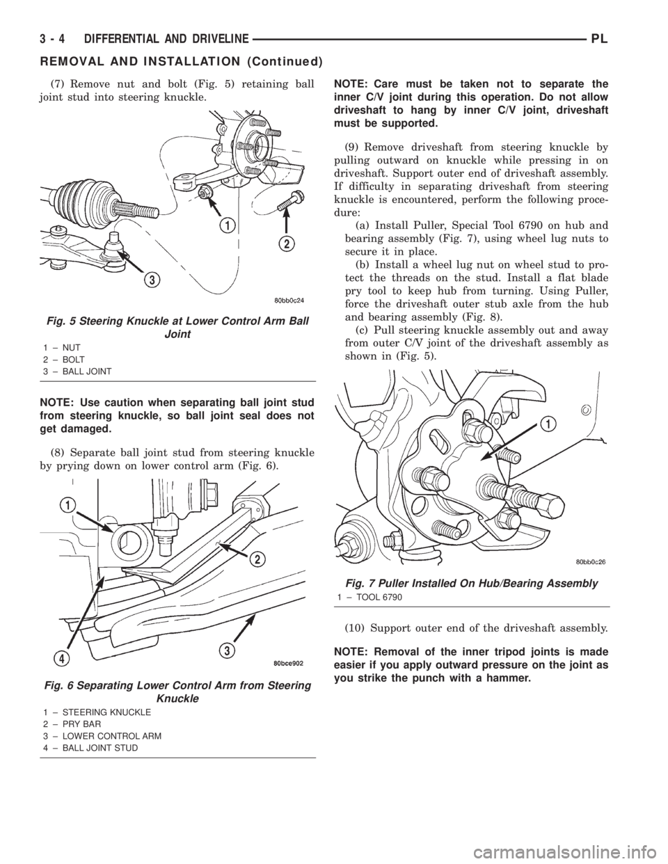
(7) Remove nut and bolt (Fig. 5) retaining ball
joint stud into steering knuckle.
NOTE: Use caution when separating ball joint stud
from steering knuckle, so ball joint seal does not
get damaged.
(8) Separate ball joint stud from steering knuckle
by prying down on lower control arm (Fig. 6).NOTE: Care must be taken not to separate the
inner C/V joint during this operation. Do not allow
driveshaft to hang by inner C/V joint, driveshaft
must be supported.
(9) Remove driveshaft from steering knuckle by
pulling outward on knuckle while pressing in on
driveshaft. Support outer end of driveshaft assembly.
If difficulty in separating driveshaft from steering
knuckle is encountered, perform the following proce-
dure:
(a) Install Puller, Special Tool 6790 on hub and
bearing assembly (Fig. 7), using wheel lug nuts to
secure it in place.
(b) Install a wheel lug nut on wheel stud to pro-
tect the threads on the stud. Install a flat blade
pry tool to keep hub from turning. Using Puller,
force the driveshaft outer stub axle from the hub
and bearing assembly (Fig. 8).
(c) Pull steering knuckle assembly out and away
from outer C/V joint of the driveshaft assembly as
shown in (Fig. 5).
(10) Support outer end of the driveshaft assembly.
NOTE: Removal of the inner tripod joints is made
easier if you apply outward pressure on the joint as
you strike the punch with a hammer.
Fig. 5 Steering Knuckle at Lower Control Arm Ball
Joint
1 ± NUT
2 ± BOLT
3 ± BALL JOINT
Fig. 6 Separating Lower Control Arm from Steering
Knuckle
1 ± STEERING KNUCKLE
2±PRYBAR
3 ± LOWER CONTROL ARM
4 ± BALL JOINT STUD
Fig. 7 Puller Installed On Hub/Bearing Assembly
1 ± TOOL 6790
3 - 4 DIFFERENTIAL AND DRIVELINEPL
REMOVAL AND INSTALLATION (Continued)
Page 66 of 1285
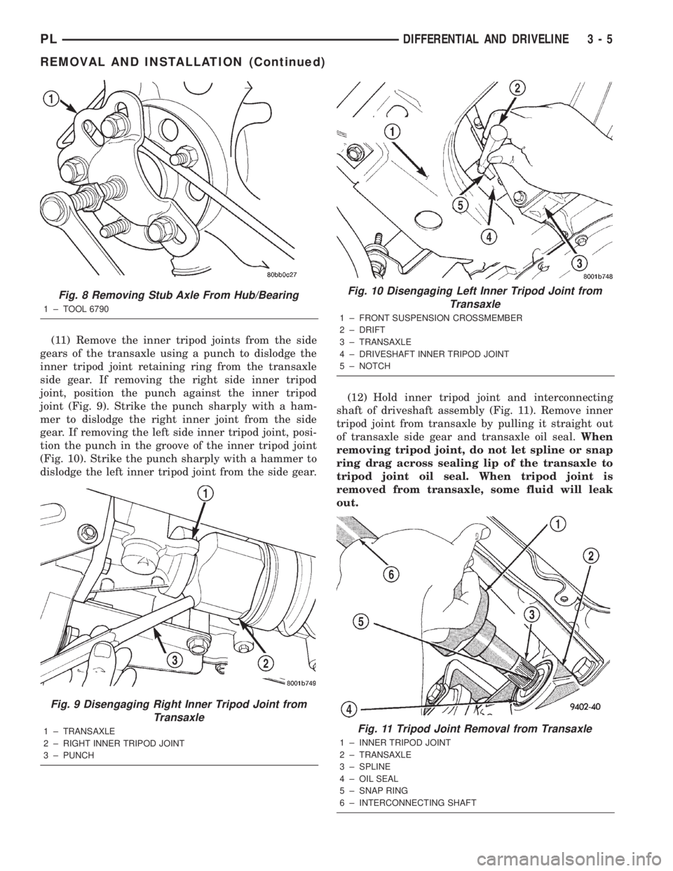
(11) Remove the inner tripod joints from the side
gears of the transaxle using a punch to dislodge the
inner tripod joint retaining ring from the transaxle
side gear. If removing the right side inner tripod
joint, position the punch against the inner tripod
joint (Fig. 9). Strike the punch sharply with a ham-
mer to dislodge the right inner joint from the side
gear. If removing the left side inner tripod joint, posi-
tion the punch in the groove of the inner tripod joint
(Fig. 10). Strike the punch sharply with a hammer to
dislodge the left inner tripod joint from the side gear.(12) Hold inner tripod joint and interconnecting
shaft of driveshaft assembly (Fig. 11). Remove inner
tripod joint from transaxle by pulling it straight out
of transaxle side gear and transaxle oil seal.When
removing tripod joint, do not let spline or snap
ring drag across sealing lip of the transaxle to
tripod joint oil seal. When tripod joint is
removed from transaxle, some fluid will leak
out.
Fig. 8 Removing Stub Axle From Hub/Bearing
1 ± TOOL 6790
Fig. 9 Disengaging Right Inner Tripod Joint from
Transaxle
1 ± TRANSAXLE
2 ± RIGHT INNER TRIPOD JOINT
3 ± PUNCH
Fig. 10 Disengaging Left Inner Tripod Joint from
Transaxle
1 ± FRONT SUSPENSION CROSSMEMBER
2 ± DRIFT
3 ± TRANSAXLE
4 ± DRIVESHAFT INNER TRIPOD JOINT
5 ± NOTCH
Fig. 11 Tripod Joint Removal from Transaxle
1 ± INNER TRIPOD JOINT
2 ± TRANSAXLE
3 ± SPLINE
4 ± OIL SEAL
5 ± SNAP RING
6 ± INTERCONNECTING SHAFT
PLDIFFERENTIAL AND DRIVELINE 3 - 5
REMOVAL AND INSTALLATION (Continued)
Page 67 of 1285
CAUTION: The driveshaft, when installed, acts as a
bolt and secures the front hub/bearing assembly. If
vehicle is to be supported or moved on its wheels
with a driveshaft removed, install a PROPER±SIZED
BOLT AND NUT through front hub. Tighten bolt and
nut to 203 N´m (150 ft. lbs.). This will ensure that
the hub bearing cannot loosen.
INSTALLATION
(1) Thoroughly clean spline and oil seal sealing
surface, on tripod joint. Lightly lubricate oil seal
sealing surface on tripod joint with fresh clean trans-
mission lubricant.
(2) Holding driveshaft assembly by tripod joint and
interconnecting shaft, install tripod joint into tran-
saxle side gear as far as possible by hand.
(3) Carefully align tripod joint with transaxle side
gears. Then grasp driveshaft interconnecting shaft
and push tripod joint into transaxle side gear until
fully seated.Test that snap ring is fully engaged
with side gear by attempting to remove tripod
joint from transaxle by hand. If snap ring is
fully engaged with side gear, tripod joint will
not be removable by hand.
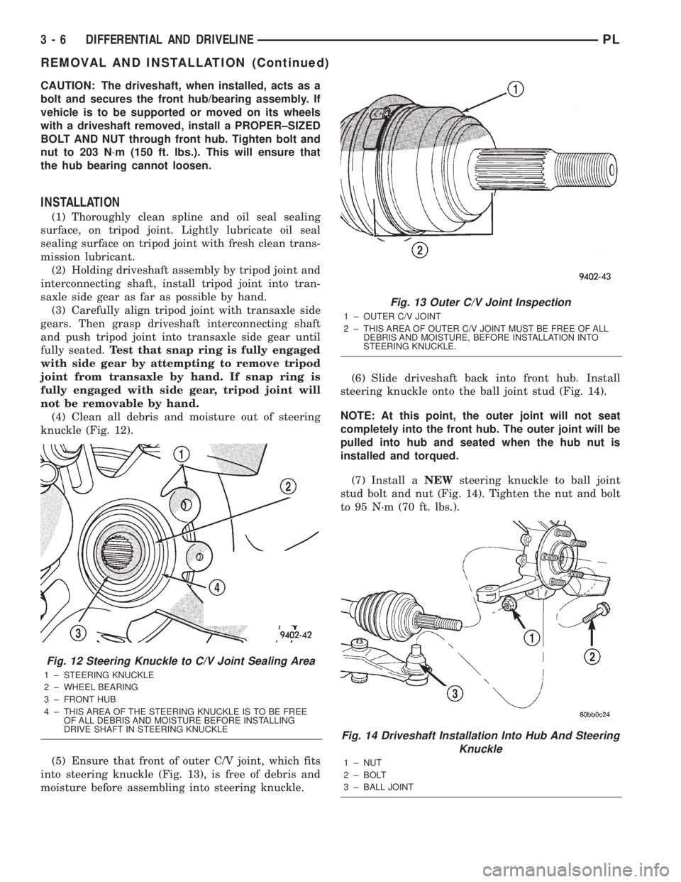
(4) Clean all debris and moisture out of steering
knuckle (Fig. 12).
(5) Ensure that front of outer C/V joint, which fits
into steering knuckle (Fig. 13), is free of debris and
moisture before assembling into steering knuckle.(6) Slide driveshaft back into front hub. Install
steering knuckle onto the ball joint stud (Fig. 14).
NOTE: At this point, the outer joint will not seat
completely into the front hub. The outer joint will be
pulled into hub and seated when the hub nut is
installed and torqued.
(7) Install aNEWsteering knuckle to ball joint
stud bolt and nut (Fig. 14). Tighten the nut and bolt
to 95 N´m (70 ft. lbs.).
Fig. 12 Steering Knuckle to C/V Joint Sealing Area
1 ± STEERING KNUCKLE
2 ± WHEEL BEARING
3 ± FRONT HUB
4 ± THIS AREA OF THE STEERING KNUCKLE IS TO BE FREE
OF ALL DEBRIS AND MOISTURE BEFORE INSTALLING
DRIVE SHAFT IN STEERING KNUCKLE
Fig. 13 Outer C/V Joint Inspection
1 ± OUTER C/V JOINT
2 ± THIS AREA OF OUTER C/V JOINT MUST BE FREE OF ALL
DEBRIS AND MOISTURE, BEFORE INSTALLATION INTO
STEERING KNUCKLE.
Fig. 14 Driveshaft Installation Into Hub And Steering
Knuckle
1 ± NUT
2 ± BOLT
3 ± BALL JOINT
3 - 6 DIFFERENTIAL AND DRIVELINEPL
REMOVAL AND INSTALLATION (Continued)
Page 68 of 1285
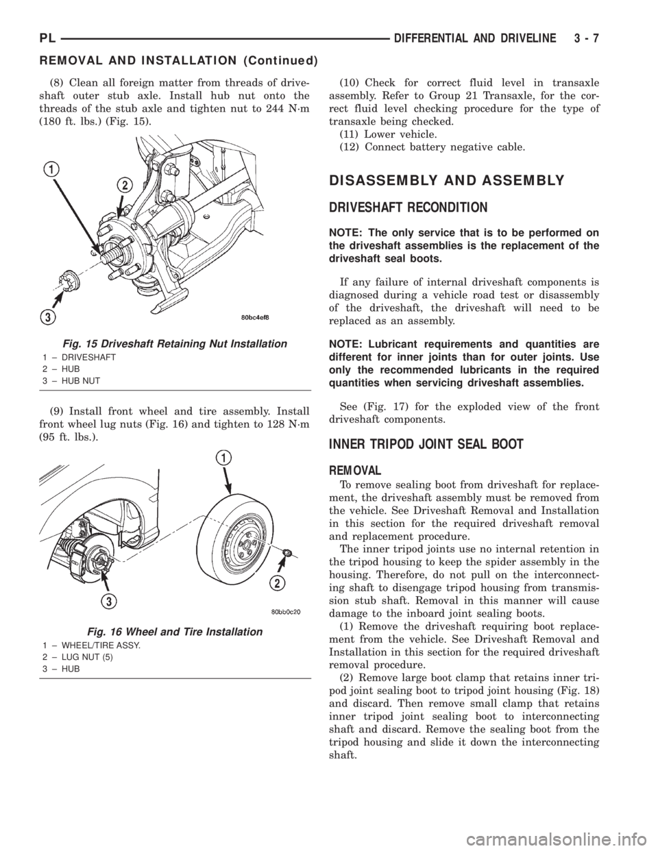
(8) Clean all foreign matter from threads of drive-
shaft outer stub axle. Install hub nut onto the
threads of the stub axle and tighten nut to 244 N´m
(180 ft. lbs.) (Fig. 15).
(9) Install front wheel and tire assembly. Install
front wheel lug nuts (Fig. 16) and tighten to 128 N´m
(95 ft. lbs.).(10) Check for correct fluid level in transaxle
assembly. Refer to Group 21 Transaxle, for the cor-
rect fluid level checking procedure for the type of
transaxle being checked.
(11) Lower vehicle.
(12) Connect battery negative cable.
DISASSEMBLY AND ASSEMBLY
DRIVESHAFT RECONDITION
NOTE: The only service that is to be performed on
the driveshaft assemblies is the replacement of the
driveshaft seal boots.
If any failure of internal driveshaft components is
diagnosed during a vehicle road test or disassembly
of the driveshaft, the driveshaft will need to be
replaced as an assembly.
NOTE: Lubricant requirements and quantities are
different for inner joints than for outer joints. Use
only the recommended lubricants in the required
quantities when servicing driveshaft assemblies.
See (Fig. 17) for the exploded view of the front
driveshaft components.
INNER TRIPOD JOINT SEAL BOOT
REMOVAL
To remove sealing boot from driveshaft for replace-
ment, the driveshaft assembly must be removed from
the vehicle. See Driveshaft Removal and Installation
in this section for the required driveshaft removal
and replacement procedure.
The inner tripod joints use no internal retention in
the tripod housing to keep the spider assembly in the
housing. Therefore, do not pull on the interconnect-
ing shaft to disengage tripod housing from transmis-
sion stub shaft. Removal in this manner will cause
damage to the inboard joint sealing boots.
(1) Remove the driveshaft requiring boot replace-
ment from the vehicle. See Driveshaft Removal and
Installation in this section for the required driveshaft
removal procedure.
(2) Remove large boot clamp that retains inner tri-
pod joint sealing boot to tripod joint housing (Fig. 18)
and discard. Then remove small clamp that retains
inner tripod joint sealing boot to interconnecting
shaft and discard. Remove the sealing boot from the
tripod housing and slide it down the interconnecting
shaft.
Fig. 15 Driveshaft Retaining Nut Installation
1 ± DRIVESHAFT
2 ± HUB
3 ± HUB NUT
Fig. 16 Wheel and Tire Installation
1 ± WHEEL/TIRE ASSY.
2 ± LUG NUT (5)
3 ± HUB
PLDIFFERENTIAL AND DRIVELINE 3 - 7
REMOVAL AND INSTALLATION (Continued)
Page 69 of 1285
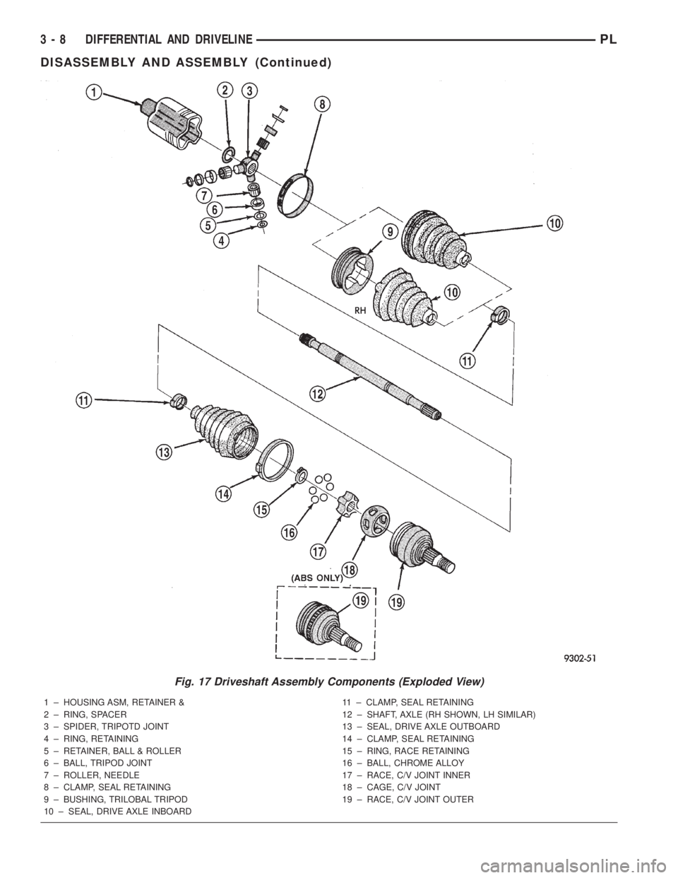
Fig. 17 Driveshaft Assembly Components (Exploded View)
1 ± HOUSING ASM, RETAINER &
2 ± RING, SPACER
3 ± SPIDER, TRIPOTD JOINT
4 ± RING, RETAINING
5 ± RETAINER, BALL & ROLLER
6 ± BALL, TRIPOD JOINT
7 ± ROLLER, NEEDLE
8 ± CLAMP, SEAL RETAINING
9 ± BUSHING, TRILOBAL TRIPOD
10 ± SEAL, DRIVE AXLE INBOARD11 ± CLAMP, SEAL RETAINING
12 ± SHAFT, AXLE (RH SHOWN, LH SIMILAR)
13 ± SEAL, DRIVE AXLE OUTBOARD
14 ± CLAMP, SEAL RETAINING
15 ± RING, RACE RETAINING
16 ± BALL, CHROME ALLOY
17 ± RACE, C/V JOINT INNER
18 ± CAGE, C/V JOINT
19 ± RACE, C/V JOINT OUTER
3 - 8 DIFFERENTIAL AND DRIVELINEPL
DISASSEMBLY AND ASSEMBLY (Continued)