refill cooling system DODGE NEON 2000 Service Repair Manual
[x] Cancel search | Manufacturer: DODGE, Model Year: 2000, Model line: NEON, Model: DODGE NEON 2000Pages: 1285, PDF Size: 29.42 MB
Page 180 of 1285
COOLING SYSTEM
TABLE OF CONTENTS
page page
DESCRIPTION AND OPERATION
COOLING SYSTEM........................1
COOLANT...............................2
COOLANT PERFORMANCE..................2
COOLANT RECOVERY SYSTEM..............3
ENGINE THERMOSTAT.....................3
RADIATOR..............................3
RADIATOR COOLING FAN MODULE...........3
COOLING SYSTEM PRESSURE CAP..........4
RADIATOR HOSES AND CLAMPS............5
WATER PUMP...........................5
AUTOMATIC TRANSMISSION OIL COOLER.....6
ACCESSORY DRIVE BELTS.................6
ENGINE BLOCK HEATER...................6
DIAGNOSIS AND TESTING
COOLING SYSTEM DIAGNOSIS..............7
ENGINE THERMOSTAT TESTING............14
ACCESSORY DRIVE BELT DIAGNOSIS........14
WATER PUMP DIAGNOSIS................15
COOLING SYSTEM FLOW CHECK...........15
ELECTRIC FAN MOTOR TEST...............15
COOLANT CONCENTRATION TESTING........15
TESTING COOLING SYSTEM FOR LEAKS.....15
PRESSURE CAP TO FILLER NECK SEAL
PRESSURE RELIEF CHECK...............16
PRESSURE TESTING COOLING SYSTEM
PRESSURE CAP.......................16
LOW COOLANT LEVEL AERATION...........17
DEAERATION...........................17
TEMPERATURE GAUGE INDICATION.........17
ENGINE BLOCK HEATER..................17
SERVICE PROCEDURES
COOLANT LEVEL CHECKÐROUTINE.........17COOLANTÐADDING ADDITIONAL...........18
COOLANT LEVELÐSERVICING.............18
COOLING SYSTEMÐDRAINING.............19
COOLING SYSTEMÐREFILLING............19
REMOVAL AND INSTALLATION
WATER PUMP..........................19
WATER PUMP INLET TUBE................20
ENGINE THERMOSTAT....................20
RADIATOR.............................21
RADIATOR DRAINCOCK...................22
COOLING FAN MODULE...................22
COOLANT RECOVERY CONTAINER..........23
ENGINE BLOCK HEATER..................24
ACCESSORY DRIVE BELTS................24
AUTOMATIC BELT TENSIONER & PULLEY....26
DISASSEMBLY AND ASSEMBLY
COOLING FAN MODULE...................26
CLEANING AND INSPECTION
WATER PUMP..........................28
ACCESSORY DRIVE BELT INSPECTION.......28
COOLING SYSTEM CAP...................28
COOLING SYSTEM CLEANING..............28
RADIATOR FLUSHING....................28
REVERSE FLUSHING.....................29
CHEMICAL CLEANING....................29
ADJUSTMENTS
BELT TENSION..........................29
SPECIFICATIONS
COOLING SYSTEM CAPACITY..............30
TORQUE SPECIFICATIONS.................30
SPECIAL TOOLS
COOLING..............................30
DESCRIPTION AND OPERATION
COOLING SYSTEM
The cooling system consists of an engine cooling
module, thermostat, coolant, and a water pump to
circulate the coolant. The engine cooling module may
consist of a radiator, electric fan motor, fan, shroud,
coolant reserve system, transmission oil cooler, hoses,clamps, air conditioning condenser and transmission
oil lines.
²When the Engine is cold: The thermostat is
closed and the cooling system has no flow through
the radiator. The coolant flows through the engine,
heater system and bypass.
²When the Engine is warm: Thermostat is open
and the cooling system has flow through the radiator,
engine, heater system, and bypass.
PLCOOLING SYSTEM 7 - 1
Page 194 of 1285
WATER PUMP DIAGNOSIS
A quick flow test to tell whether or not the pump is
working is to see if the heater warms properly. A
defective pump will not be able to circulate heated
coolant through the long heater hose.
Another flow test to help determine pump opera-
tion:
WARNING: DO NOT remove radiator cap if the cool-
ing system is hot or under pressure.
(1) Remove cooling system pressure cap.
(2) Remove a small amount of coolant from the
system.
(3) Start the engine and warm up until thermostat
opens.
(4) With the thermostat open and coolant level low,
visually inspect for coolant flow. If flow is present,
the water pump is pumping coolant through the sys-
tem.
COOLING SYSTEM FLOW CHECK
To determine whether coolant is flowing through
the cooling system, use the following procedures:
(1) If engine is cold, idle engine until normal oper-
ating temperature is reached. Then feel the upper
radiator hose. If it is hot, coolant is circulating.
WARNING: DO NOT REMOVE THE COOLING SYS-
TEM PRESSURE CAP WITH THE SYSTEM HOT AND
UNDER PRESSURE BECAUSE SERIOUS BURNS
FROM COOLANT CAN OCCUR.
(2) Remove pressure cap when engine is cold,
remove small amount of coolant Idle engine until
thermostat opens, you should observe coolant flow
while looking down the filler neck. Once flow is
detected install the pressure cap.
ELECTRIC FAN MOTOR TEST
Refer to Powertrain Diagnostic Manual for proce-
dure.
COOLANT CONCENTRATION TESTING
Coolant concentration should be checked when any
additional coolant was added to system or after a
coolant drain, flush and refill. The coolant mixture
offers optimum engine cooling and protection against
corrosion when mixed to a freeze point of -37ÉC
(-34ÉF) to -59ÉC (-50ÉF). The use of a hydrometer or a
refractometer can be used to test coolant concentra-
tion.
A hydrometer will test the amount of glycol in a
mixture by measuring the specific gravity of the mix-
ture. The higher the concentration of ethylene glycol,
the larger the number of balls that will float, andhigher the freeze protection (up to a maximum of
70% by volume glycol).
A refractometer will test the amount of glycol in a
coolant mixture by measuring the amount a beam of
light bends as it passes through the fluid.
Some coolant manufactures use other types of gly-
cols into their coolant formulations. Propylene glycol
is the most common new coolant. However, propylene
glycol based coolants do not provide the same freez-
ing protection and corrosion protection and is only
recommended for limited usage. Refer to appropriate
Technical Service Bulletin(s) regarding use of propy-
lene glycol based coolants.
CAUTION: Do not mix types of coolantÐcorrosion
protection will be severely reduced.
Because ethylene glycol and propylene glycol do
not have the same specific gravities, the use of a
hydrometer will be inaccurate. Therefore, Special
Tool 8286 refractometer, is recommended when test-
ing either ethylene or propylene glycol coolants.
TESTING COOLING SYSTEM FOR LEAKS
The system should be full. With the engine not
running, wipe the filler neck sealing seat clean.
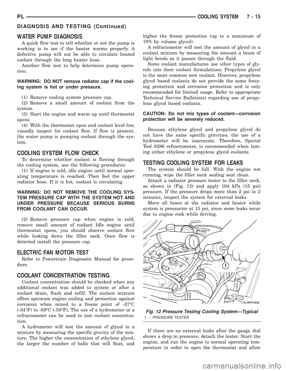
Attach a radiator pressure tester to the filler neck,
as shown in (Fig. 12) and apply 104 kPa (15 psi)
pressure. If the pressure drops more than 2 psi in 2
minutes, inspect the system for external leaks.
Move all hoses at the radiator and heater while
system is pressurize at 15 psi, since some leaks occur
due to engine rock while driving.
If there are no external leaks after the gauge dial
shows a drop in pressure, detach the tester. Start the
engine, and run the engine to normal operating tem-
perature in order to open the thermostat and allow
Fig. 12 Pressure Testing Cooling SystemÐTypical
1 ± PRESSURE TESTER
PLCOOLING SYSTEM 7 - 15
DIAGNOSIS AND TESTING (Continued)
Page 195 of 1285
the coolant to expand. Reattach the tester. If the nee-
dle on the dial fluctuates it indicates a combustion
leak, usually a head gasket leak.
WARNING: WITH THE PRESSURE TESTER IN
PLACE PRESSURE BUILDS UP QUICKLY. ANY
EXCESSIVE PRESSURE BUILD-UP DUE TO CON-
TINUOUS ENGINE OPERATION MUST BE
RELEASED TO A SAFE PRESSURE POINT. NEVER
PERMIT PRESSURE TO EXCEED 138 kPa (20 psi).
If the needle on the dial does not fluctuate, race
the engine a few times. If an abnormal amount of
coolant or steam is emitted from the tail pipe, it may
indicate a faulty head gasket, cracked engine block,
or cracked cylinder head.
There may be internal leaks, which can be deter-
mined by removing the oil dipstick. If water globules
appear intermixed with the oil, it indicates an inter-
nal leak in the engine. If there is an internal leak,
the engine must be disassembled for repair.
PRESSURE CAP TO FILLER NECK SEAL
PRESSURE RELIEF CHECK
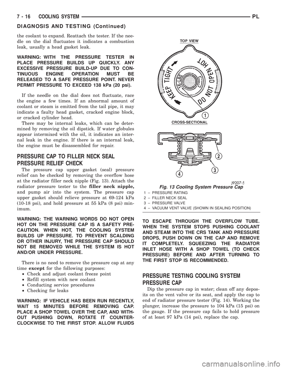
The pressure cap upper gasket (seal) pressure
relief can be checked by removing the overflow hose
at the radiator filler neck nipple (Fig. 13). Attach the
radiator pressure tester to thefiller neck nipple,
and pump air into the system. The pressure cap
upper gasket should relieve pressure at 69-124 kPa
(10-18 psi), and hold pressure at 55 kPa (8 psi) min-
imum.
WARNING: THE WARNING WORDS DO NOT OPEN
HOT ON THE PRESSURE CAP IS A SAFETY PRE-
CAUTION. WHEN HOT, THE COOLING SYSTEM
BUILDS UP PRESSURE. TO PREVENT SCALDING
OR OTHER INJURY, THE PRESSURE CAP SHOULD
NOT BE REMOVED WHILE THE SYSTEM IS HOT
AND/OR UNDER PRESSURE.
There is no need to remove the pressure cap at any
timeexceptfor the following purposes:
²Check and adjust coolant freeze point
²Refill system with new coolant
²Conducting service procedures
²Checking for leaks
WARNING: IF VEHICLE HAS BEEN RUN RECENTLY,
WAIT 15 MINUTES BEFORE REMOVING CAP.
PLACE A SHOP TOWEL OVER THE CAP, AND WITH-
OUT PUSHING DOWN, ROTATE IT COUNTER-
CLOCKWISE TO THE FIRST STOP. ALLOW FLUIDSTO ESCAPE THROUGH THE OVERFLOW TUBE.
WHEN THE SYSTEM STOPS PUSHING COOLANT
AND STEAM INTO THE CRS TANK AND PRESSURE
DROPS, PUSH DOWN ON THE CAP AND REMOVE
IT COMPLETELY. SQUEEZING THE RADIATOR
INLET HOSE WITH A SHOP TOWEL (TO CHECK
PRESSURE) BEFORE AND AFTER TURNING TO
THE FIRST STOP IS RECOMMENDED.
PRESSURE TESTING COOLING SYSTEM
PRESSURE CAP
Dip the pressure cap in water; clean off any depos-
its on the vent valve or its seat, and apply the cap to
end of radiator pressure tester (Fig. 14). Working the
plunger, increase the pressure to 104 kPa (15 psi) on
the gauge. If the pressure cap fails to hold pressure
of at least 97 kPa (14 psi), replace the cap.
Fig. 13 Cooling System Pressure Cap
1 ± PRESSURE RATING
2 ± FILLER NECK SEAL
3 ± PRESSURE VALVE
4 ± VACUUM VENT VALVE (SHOWN IN SEALING POSITION)
7 - 16 COOLING SYSTEMPL
DIAGNOSIS AND TESTING (Continued)
Page 198 of 1285
COOLING SYSTEMÐDRAINING
NOTE: Drain, flush, and fill the cooling system at
the mileage or time intervals specified in Group 0,
Lubrication and Maintenance. If the solution is dirty,
rusty, or contains a considerable amount of sedi-
ment; clean and flush with a reliable cooling system
cleaner. Care should be taken in disposing of the
used engine coolant from your vehicle. Check gov-
ernmental regulations for disposal of used engine
coolant.
Without removing radiator pressure cap and
with system not under pressure:
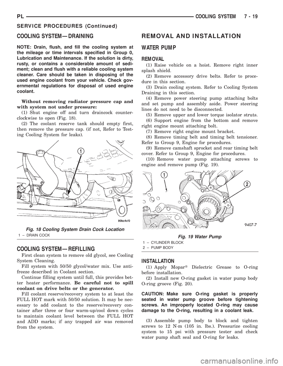
(1) Shut engine off and turn draincock counter-
clockwise to open (Fig. 18).
(2) The coolant reserve tank should empty first,
then remove the pressure cap. (if not, Refer to Test-
ing Cooling System for leaks).
COOLING SYSTEMÐREFILLING
First clean system to remove old glycol, see Cooling
System Cleaning.
Fill system with 50/50 glycol/water mix. Use anti-
freeze described in Coolant section.
Continue filling system until full, this provides bet-
ter heater performance.Be careful not to spill
coolant on drive belts or the generator.
Fill coolant reserve/recovery system to at least the
FULL HOT mark with 50/50 solution. It may be nec-
essary to add coolant to the reserve/recovery con-
tainer after three or four warm-up/cool down cycles
to maintain coolant level between the FULL HOT
and ADD marks; if any trapped air was removed
from the system.
REMOVAL AND INSTALLATION
WATER PUMP
REMOVAL
(1) Raise vehicle on a hoist. Remove right inner
splash shield.
(2) Remove accessory drive belts. Refer to proce-
dure in this section.
(3) Drain cooling system. Refer to Cooling System
Draining in this section.
(4) Remove power steering pump attaching bolts
and set pump and assembly aside. Power steering
lines do not need to be disconnected.
(5) Remove upper and lower torque isolator struts.
(6) Support engine from the bottom and remove
right engine mount attaching bolt.
(7) Remove right engine mount bracket.
(8) Remove timing belt and timing belt tensioner.
Refer to Group 9, Engine for procedures.
(9) Remove camshaft sprocket and rear timing belt
cover. Refer to Group 9, Engine for procedures.
(10) Remove water pump attaching screws to
engine and remove pump (Fig. 19).
INSTALLATION
(1) Apply MopartDielectric Grease to O-ring
before installation.
(2) Install new O-ring gasket in water pump body
O-ring groove (Fig. 20).
CAUTION: Make sure O-ring gasket is properly
seated in water pump groove before tightening
screws. An improperly located O-ring may cause
damage to the O-ring, resulting in a coolant leak.
(3) Assemble pump body to block and tighten
screws to 12 N´m (105 in. lbs.). Pressurize cooling
system to 15 psi with pressure tester and check
water pump shaft seal and O-ring for leaks.
Fig. 18 Cooling System Drain Cock Location
1 ± DRAIN COCKFig. 19 Water Pump
1 ± CYLINDER BLOCK
2 ± PUMP BODY
PLCOOLING SYSTEM 7 - 19
SERVICE PROCEDURES (Continued)
Page 200 of 1285
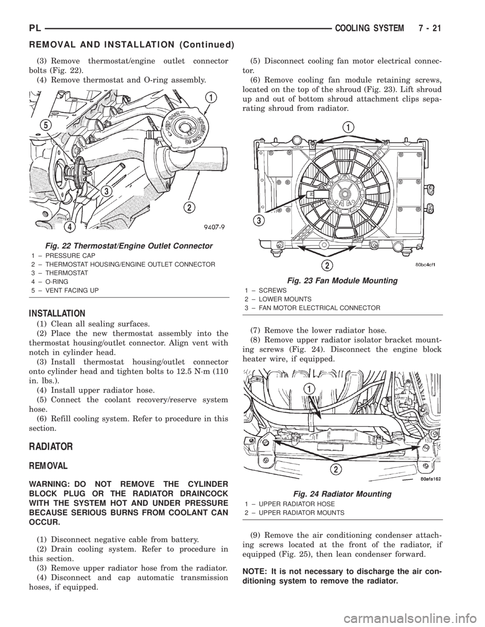
(3) Remove thermostat/engine outlet connector
bolts (Fig. 22).
(4) Remove thermostat and O-ring assembly.
INSTALLATION
(1) Clean all sealing surfaces.
(2) Place the new thermostat assembly into the
thermostat housing/outlet connector. Align vent with
notch in cylinder head.
(3) Install thermostat housing/outlet connector
onto cylinder head and tighten bolts to 12.5 N´m (110
in. lbs.).
(4) Install upper radiator hose.
(5) Connect the coolant recovery/reserve system
hose.
(6) Refill cooling system. Refer to procedure in this
section.
RADIATOR
REMOVAL
WARNING: DO NOT REMOVE THE CYLINDER
BLOCK PLUG OR THE RADIATOR DRAINCOCK
WITH THE SYSTEM HOT AND UNDER PRESSURE
BECAUSE SERIOUS BURNS FROM COOLANT CAN
OCCUR.
(1) Disconnect negative cable from battery.
(2) Drain cooling system. Refer to procedure in
this section.
(3) Remove upper radiator hose from the radiator.
(4) Disconnect and cap automatic transmission
hoses, if equipped.(5) Disconnect cooling fan motor electrical connec-
tor.
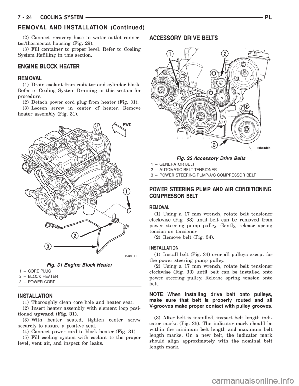
(6) Remove cooling fan module retaining screws,
located on the top of the shroud (Fig. 23). Lift shroud
up and out of bottom shroud attachment clips sepa-
rating shroud from radiator.
(7) Remove the lower radiator hose.
(8) Remove upper radiator isolator bracket mount-
ing screws (Fig. 24). Disconnect the engine block
heater wire, if equipped.
(9) Remove the air conditioning condenser attach-
ing screws located at the front of the radiator, if
equipped (Fig. 25), then lean condenser forward.
NOTE: It is not necessary to discharge the air con-
ditioning system to remove the radiator.
Fig. 22 Thermostat/Engine Outlet Connector
1 ± PRESSURE CAP
2 ± THERMOSTAT HOUSING/ENGINE OUTLET CONNECTOR
3 ± THERMOSTAT
4 ± O-RING
5 ± VENT FACING UP
Fig. 23 Fan Module Mounting
1 ± SCREWS
2 ± LOWER MOUNTS
3 ± FAN MOTOR ELECTRICAL CONNECTOR
Fig. 24 Radiator Mounting
1 ± UPPER RADIATOR HOSE
2 ± UPPER RADIATOR MOUNTS
PLCOOLING SYSTEM 7 - 21
REMOVAL AND INSTALLATION (Continued)
Page 203 of 1285
(2) Connect recovery hose to water outlet connec-
tor/thermostat housing (Fig. 29).
(3) Fill container to proper level. Refer to Cooling
System Refilling in this section.
ENGINE BLOCK HEATER
REMOVAL
(1) Drain coolant from radiator and cylinder block.
Refer to Cooling System Draining in this section for
procedure.
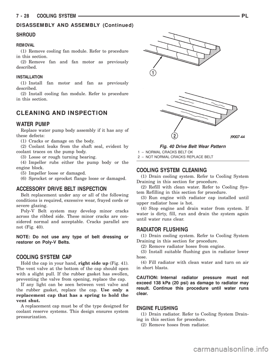
(2) Detach power cord plug from heater (Fig. 31).
(3) Loosen screw in center of heater. Remove
heater assembly (Fig. 31).
INSTALLATION
(1) Thoroughly clean core hole and heater seat.
(2) Insert heater assembly with element loop posi-
tionedupward (Fig. 31).
(3) With heater seated, tighten center screw
securely to assure a positive seal.
(4) Connect power cord to block heater (Fig. 31).
(5) Fill cooling system with coolant to the proper
level, vent air, and inspect for leaks.
ACCESSORY DRIVE BELTS
POWER STEERING PUMP AND AIR CONDITIONING
COMPRESSOR BELT
REMOVAL
(1) Using a 17 mm wrench, rotate belt tensioner
clockwise (Fig. 33) until belt can be removed from
power steering pump pulley. Gently, release spring
tension on tensioner.
(2) Remove belt (Fig. 34).
INSTALLATION
(1) Install belt (Fig. 34) over all pulleys except for
the power steering pump pulley.
(2) Using a 17 mm wrench, rotate belt tensioner
clockwise (Fig. 33) until belt can be installed onto
power steering pulley. Release spring tension onto
belt.
NOTE: When installing drive belt onto pulleys,
make sure that belt is properly routed and all
V-grooves make proper contact with pulley grooves.
(3) After belt is installed, inspect belt length indi-
cator marks (Fig. 35). The indicator mark should be
within the minimum belt length and maximum belt
length marks. On a new belt, the indicator mark
should align approximately with the nominal belt
length mark.
Fig. 31 Engine Block Heater
1 ± CORE PLUG
2 ± BLOCK HEATER
3 ± POWER CORD
Fig. 32 Accessory Drive Belts
1 ± GENERATOR BELT
2 ± AUTOMATIC BELT TENSIONER
3 ± POWER STEERING PUMP/A/C COMPRESSOR BELT
7 - 24 COOLING SYSTEMPL
REMOVAL AND INSTALLATION (Continued)
Page 207 of 1285
SHROUD
REMOVAL
(1) Remove cooling fan module. Refer to procedure
in this section.
(2) Remove fan and fan motor as previously
described.
INSTALLATION
(1) Install fan motor and fan as previously
described.
(2) Install cooling fan module. Refer to procedure
in this section.
CLEANING AND INSPECTION
WATER PUMP
Replace water pump body assembly if it has any of
these defects:
(1) Cracks or damage on the body.
(2) Coolant leaks from the shaft seal, evident by
coolant traces on the pump body.
(3) Loose or rough turning bearing.
(4) Impeller rubs either the pump body or the
engine block.
(5) Impeller loose or damaged.
(6) Sprocket or sprocket flange loose or damaged.
ACCESSORY DRIVE BELT INSPECTION
Belt replacement under any or all of the following
conditions is required, excessive wear, frayed cords or
severe glazing.
Poly-V Belt system may develop minor cracks
across the ribbed side. These minor cracks are con-
sidered normal and acceptable. Cracks parallel are
not (Fig. 40).
NOTE: Do not use any type of belt dressing or
restorer on Poly-V Belts.
COOLING SYSTEM CAP
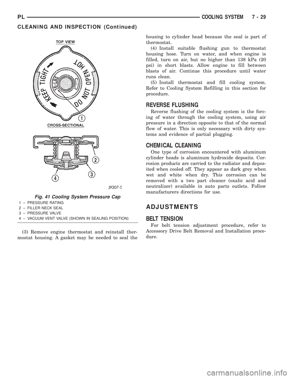
Hold the cap in your hand,right side up(Fig. 41).
The vent valve at the bottom of the cap should open
with a slight pull. If the rubber gasket has swollen,
preventing the valve from opening, replace the cap.
If any light can be seen between vent valve and
the rubber gasket, replace the cap.Use only a
replacement cap that has a spring to hold the
vent shut.
A replacement cap must be of the type designed for
coolant reserve systems. This design ensures system
pressurization.
COOLING SYSTEM CLEANING
(1) Drain cooling system. Refer to Cooling System
Draining in this section for procedure.
(2) Refill with clean water. Refer to Cooling Sys-
tem Refilling in this section for procedure.
(3) Run engine with radiator cap installed until
upper radiator hose is hot.
(4) Stop engine and drain water from system. If
water is dirty, fill, run and drain the system again
until water runs clear.
RADIATOR FLUSHING
(1) Drain cooling system. Refer to Cooling System
Draining in this section for procedure.
(2) Remove radiator hoses from engine.
(3) Install suitable flushing gun in radiator lower
hose.
(4) Fill radiator with clean water and turn on air
in short blasts.
CAUTION: Internal radiator pressure must not
exceed 138 kPa (20 psi) as damage to radiator may
result. Continue this procedure until water runs
clear.
ENGINE FLUSHING
(1) Drain radiator. Refer to Cooling System Drain-
ing in this section for procedure.
(2) Remove hoses from radiator.
Fig. 40 Drive Belt Wear Pattern
1 ± NORMAL CRACKS BELT OK
2 ± NOT NORMAL CRACKS REPLACE BELT
7 - 28 COOLING SYSTEMPL
DISASSEMBLY AND ASSEMBLY (Continued)
Page 208 of 1285
(3) Remove engine thermostat and reinstall ther-
mostat housing. A gasket may be needed to seal thehousing to cylinder head because the seal is part of
thermostat.
(4) Install suitable flushing gun to thermostat
housing hose. Turn on water, and when engine is
filled, turn on air, but no higher than 138 kPa (20
psi) in short blasts. Allow engine to fill between
blasts of air. Continue this procedure until water
runs clean.
(5) Install thermostat and fill cooling system.
Refer to Cooling System Refilling in this section for
procedure.
REVERSE FLUSHING
Reverse flushing of the cooling system is the forc-
ing of water through the cooling system, using air
pressure in a direction opposite to that of the normal
flow of water. This is only necessary with dirty sys-
tems and evidence of partial plugging.
CHEMICAL CLEANING
One type of corrosion encountered with aluminum
cylinder heads is aluminum hydroxide deposits. Cor-
rosion products are carried to the radiator and depos-
ited when cooled off. They appear as dark grey when
wet and white when dry. This corrosion can be
removed with a two part cleaner (oxalic acid and
neutralizer) available in auto parts outlets. Follow
manufacturers directions for use.
ADJUSTMENTS
BELT TENSION
For belt tension adjustment procedure, refer to
Accessory Drive Belt Removal and Installation proce-
dure.
Fig. 41 Cooling System Pressure Cap
1 ± PRESSURE RATING
2 ± FILLER NECK SEAL
3 ± PRESSURE VALVE
4 ± VACUUM VENT VALVE (SHOWN IN SEALING POSITION)
PLCOOLING SYSTEM 7 - 29
CLEANING AND INSPECTION (Continued)
Page 726 of 1285
CAUTION: Do not drive cup plug into the casting
as restricted cooling can result and cause serious
engine problems.
INSTALLATION
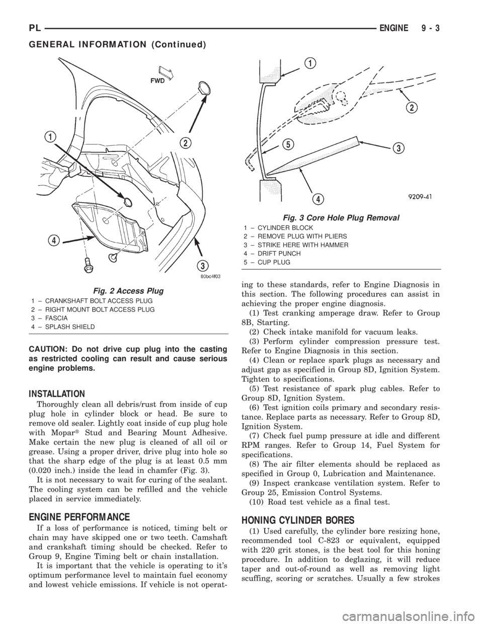
Thoroughly clean all debris/rust from inside of cup
plug hole in cylinder block or head. Be sure to
remove old sealer. Lightly coat inside of cup plug hole
with MopartStud and Bearing Mount Adhesive.
Make certain the new plug is cleaned of all oil or
grease. Using a proper driver, drive plug into hole so
that the sharp edge of the plug is at least 0.5 mm
(0.020 inch.) inside the lead in chamfer (Fig. 3).
It is not necessary to wait for curing of the sealant.
The cooling system can be refilled and the vehicle
placed in service immediately.
ENGINE PERFORMANCE
If a loss of performance is noticed, timing belt or
chain may have skipped one or two teeth. Camshaft
and crankshaft timing should be checked. Refer to
Group 9, Engine Timing belt or chain installation.
It is important that the vehicle is operating to it's
optimum performance level to maintain fuel economy
and lowest vehicle emissions. If vehicle is not operat-ing to these standards, refer to Engine Diagnosis in
this section. The following procedures can assist in
achieving the proper engine diagnosis.
(1) Test cranking amperage draw. Refer to Group
8B, Starting.
(2) Check intake manifold for vacuum leaks.
(3) Perform cylinder compression pressure test.
Refer to Engine Diagnosis in this section.
(4) Clean or replace spark plugs as necessary and
adjust gap as specified in Group 8D, Ignition System.
Tighten to specifications.
(5) Test resistance of spark plug cables. Refer to
Group 8D, Ignition System.
(6) Test ignition coils primary and secondary resis-
tance. Replace parts as necessary. Refer to Group 8D,
Ignition System.
(7) Check fuel pump pressure at idle and different
RPM ranges. Refer to Group 14, Fuel System for
specifications.
(8) The air filter elements should be replaced as
specified in Group 0, Lubrication and Maintenance.
(9) Inspect crankcase ventilation system. Refer to
Group 25, Emission Control Systems.
(10) Road test vehicle as a final test.HONING CYLINDER BORES
(1) Used carefully, the cylinder bore resizing hone,
recommended tool C-823 or equivalent, equipped
with 220 grit stones, is the best tool for this honing
procedure. In addition to deglazing, it will reduce
taper and out-of-round as well as removing light
scuffing, scoring or scratches. Usually a few strokes
Fig. 2 Access Plug
1 ± CRANKSHAFT BOLT ACCESS PLUG
2 ± RIGHT MOUNT BOLT ACCESS PLUG
3 ± FASCIA
4 ± SPLASH SHIELD
Fig. 3 Core Hole Plug Removal
1 ± CYLINDER BLOCK
2 ± REMOVE PLUG WITH PLIERS
3 ± STRIKE HERE WITH HAMMER
4 ± DRIFT PUNCH
5 ± CUP PLUG
PLENGINE 9 - 3
GENERAL INFORMATION (Continued)
Page 888 of 1285
reduces the power required to drive the pump and
holds down temperature build-up.
When steering conditions exceed maximum pres-
sure requirements, such as when the wheels are
turned against the stops, the pressure built up in the
steering gear exerts pressure on the spring end of the
flow control valve. The high pressure lifts the relief
valve ball from its seat and allows oil to flow through
a trigger orifice located in the outlet fitting. This
reduces pressure on the spring end of the flow con-
trol valve which then opens and allows the oil to
return to the intake side of the pump. This action
limits maximum pressure output of the pump to a
safe level.
Under normal power steering pump operating con-
ditions, pressure requirements of the pump are below
maximum, causing the pressure relief valve to
remain closed.
POWER STEERING FLUID RESERVOIR
The power steering fluid reservoir is mounted on
the power steering pump using 3 bolts (Fig. 1). It
stores fluid for the power steering system.
The power steering fluid reservoir is considered an
integral part of the power steering pump and is not
serviced separately.
SERVICE PROCEDURES
POWER STEERING PUMP INITIAL OPERATION
CAUTION: The fluid level should be checked with
engine off to prevent injury from moving compo-
nents. Use only MoparTPower Steering Fluid. Do
not use automatic transmission fluid. Do not over-
fill.
Wipe the filler cap clean, then check the fluid level.
The dipstick should indicateCOLDwhen the fluid is
at normal temperature, approximately 21ÉC to 27ÉC
(70ÉF to 80ÉF).
(1) Fill the power steering fluid reservoir to the
proper level and let the fluid settle for at least two
minutes.
(2) Start the engine and let run for a few seconds,
then turn the engine off.
(3) Add fluid if necessary. Repeat the above proce-
dure until the fluid level remains constant after run-
ning the engine.
(4) Raise the front wheels off the ground.
(5) Start the engine. Slowly turn the steering
wheel right and left, lightly contacting the wheel
stops.
(6) Add power steering fluid if necessary.
(7) Lower the vehicle and turn the steering wheel
slowly from lock to lock.(8) Stop the engine. Check the fluid level and refill
as required.
(9) If the fluid is extremely foamy, allow the vehi-
cle to stand a few minutes and repeat the above pro-
cedure.
REMOVAL AND INSTALLATION
SERVICE WARNINGS AND CAUTIONS
WARNING: POWER STEERING FLUID, ENGINE
PARTS AND EXHAUST SYSTEM MAY BE
EXTREMELY HOT IF ENGINE HAS BEEN RUNNING.
DO NOT START ENGINE WITH ANY LOOSE OR DIS-
CONNECTED HOSES. DO NOT ALLOW HOSES TO
TOUCH HOT EXHAUST MANIFOLD OR CATALYST.
WARNING: FLUID LEVEL SHOULD BE CHECKED
WITH THE ENGINE OFF TO PREVENT PERSONAL
INJURY FROM MOVING PARTS.
CAUTION: When the system is open, cap all open
ends of the hoses, power steering pump fittings or
power steering gear ports to prevent entry of for-
eign material into the components.
NOTE: Do not use any type of automatic transmis-
sion fluid in the power steering system.
POWER STEERING PUMP
NOTE: Before proceeding with this removal and
installation procedure, review SERVICE WARNINGS
AND CAUTIONS at the beginning of REMOVAL AND
INSTALLATION in this section.
REMOVAL
(1) Remove battery cable from the negative post on
the battery.
(2) Siphon as much fluid as possible from the
power steering fluid reservoir.
(3) Remove the power steering pump drive belt
from the power steering pump pulley. Refer to
ACCESSORY DRIVE BELTS in the COOLING SYS-
TEM service manual group for the required removal
and installation procedure.
(4) Remove the hose clamp securing the return
hose to the power steering fluid reservoir. Slide the
hose off the end of the reservoir fitting. (Fig. 2).
(5) Back out the tube nut securing the power
steering fluid pressure hose to the power steering
pump and remove the hose from the pump (Fig. 2).
PLSTEERING 19 - 17
DESCRIPTION AND OPERATION (Continued)