length DODGE NEON 2000 Service Repair Manual
[x] Cancel search | Manufacturer: DODGE, Model Year: 2000, Model line: NEON, Model: DODGE NEON 2000Pages: 1285, PDF Size: 29.42 MB
Page 25 of 1285
CAUTION: No attempt should be made to service
the headless grease fitting on the ball joint. It has
been purposely snapped off by the manufacturer to
avoid over-greasing.
STABILIZER BAR (FRONT)
Inspect for broken, cracked or distorted stabilizer
bar cushions and retainers. Inspect for worn or dam-
aged stabilizer bar links (Fig. 1).
SERVICE PROCEDURES
LUBRICATION
There are no serviceable lubrication points on the
front suspension. The front lower ball joints have
grease fittings which have had the head snapped off
by the manufacturer after they have been filled. This
has been done to eliminate the possibility of damag-
ing the non-vented seals. Grease will not leak from
the broken grease fittings. The ball joints are sealed
for life and require no maintenance.
CAUTION: No attempt should be made to replace
the ball joint grease fitting with a new fitting, then
filling the ball joint with grease. Damage to the
grease seal can result.
REMOVAL AND INSTALLATION
SERVICE WARNINGS AND CAUTIONS
WARNING: DO NOT REMOVE THE STRUT SHAFT
NUT WHILE STRUT ASSEMBLY IS INSTALLED IN
VEHICLE, OR BEFORE THE COIL SPRING IS COM-
PRESSED WITH A COMPRESSION TOOL. THE
SPRING IS HELD UNDER HIGH PRESSURE.
CAUTION: Only frame contact hoisting equipment
can be used on this vehicle. All vehicles have a
fully independent rear suspension. The vehicles
cannot be hoisted using equipment designed to lift
a vehicle by the rear axle. If this type of hoisting
equipment is used, damage to rear suspension
components will occur.
CAUTION: At no time when servicing a vehicle can
a sheet metal screw, bolt, or other metal fastener be
installed in the shock tower to take the place of an
original plastic clip. It may come into contact with
the strut or coil spring.CAUTION: Wheel bearing damage will result if after
loosening the hub nut, the vehicle is rolled on the
ground or the weight of the vehicle is allowed to be
supported by the tires for a length of time.
STRUT ASSEMBLY (FRONT)
NOTE: Before proceeding with this procedure,
review SERVICE WARNINGS AND CAUTIONS at the
beginning of REMOVAL AND INSTALLATION in this
section.
REMOVAL
(1) Raise the vehicle. Refer to HOISTING in the
LUBRICATION AND MAINTENANCE group for the
proper lifting procedure.
(2) Remove tire and wheel assembly from location
on front of vehicle requiring strut removal.
(3) If both strut assemblies are to be removed,
mark the strut assemblies right or left according to
which side of the vehicle they were removed from.
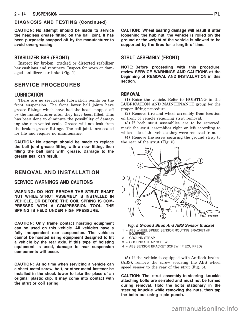
(4) Remove the screw securing the ground strap to
the rear of the strut (Fig. 5).
(5) If the vehicle is equipped with Antilock brakes
(ABS), remove the screw securing the ABS wheel
speed sensor to the rear of the strut (Fig. 5).
CAUTION: The strut assembly-to-steering knuckle
attaching bolts are serrated and must not be turned
during removal. Hold the bolts stationary in the
steering knuckle while removing the nuts, then tap
the bolts out using a pin punch.
Fig. 5 Ground Strap And ABS Sensor Bracket
1 ± ABS WHEEL SPEED SENSOR ROUTING BRACKET (IF
EQUIPPED)
2 ± GROUND STRAP
3 ± GROUND STRAP SCREW
4 ± ABS SENSOR BRACKET SCREW (IF EQUIPPED)
2 - 14 SUSPENSIONPL
DIAGNOSIS AND TESTING (Continued)
Page 56 of 1285
LATERAL ARMS
NOTE: Before proceeding with this procedure,
review SERVICE WARNINGS AND CAUTIONS at the
beginning of REMOVAL AND INSTALLATION in this
section.
Use the following procedure for removal and instal-
lation of one or both lateral arms on one side of the
vehicle's rear suspension.
REMOVAL
(1) Raise the vehicle. Refer to HOISTING in the
LUBRICATION AND MAINTENANCE group for the
proper lifting procedure.
(2) Remove the rear tire and wheel assembly.
(3) Remove the nut, bolt and washers attaching
both lateral arms to the knuckle (Fig. 1).
(4) Remove nut, washer, bolt and wheel alignment
cam attaching the lateral arms to the rear crossmem-
ber (Fig. 1).
(5) Remove the lateral arms from vehicle.
INSTALLATION
NOTE: Both lateral arms when being installed,
must be specifically positioned and orientated on
the vehicle. The lateral arm that has the same size
bushing sleeves on both ends must be mounted on
the forward side of the crossmember and knuckle
with the trimmed outer edge facing rearward. This
front arm is also marked with the word ªFOR-
WARDº. The side of the arm displaying this must
face forward.
The lateral arm with two different size bushing
sleeves must be mounted on the rearward side of
the crossmember and knuckle. Position the smaller
bushing sleeve end at the knuckle and the larger
bushing sleeve end at the rear crossmember (the
larger bushing sleeve is necessary to accommodate
the rear wheel alignment adjustment cam). If the
rear arm is to be mounted on the right side, the
trimmed outer edge must face rearward. If the rear
arm is to be mounted on the left side, the trimmed
outer edge must face forward.
(1) Following the note above, place the forward lat-
eral arm against the leading end of the knuckle, and
then install the short lateral arm mounting bolt with
a washer through the lateral arm and knuckle and
out the trailing end of the knuckle (Fig. 1).
(2) Following the note above, install the small
bushing sleeved end of the rear lateral arm onto the
end of the bolt just installed through the knuckle
(Fig. 1). Install a washer and nut onto the end of the
mounting bolt, but do not completely tighten the bolt
at this time.(3) Install a wheel alignment adjustment cam on
the long arm mounting bolt.
(4) Hold the rear lateral arm up against the cross-
member and install the long mounting bolt with the
adjustment cam through the lateral arm bushing and
rear crossmember (Fig. 1). The bolt must be installed
with the notch in the adjustment cam pointing
straight up.
(5) Position the forward lateral arm against the
rear crossmember hole. Pass the long mounting bolt
through the lateral arm bushing sleeve.
(6) Install a washer and nut onto the end of lateral
arm mounting bolt at the rear crossmember, but do
not completely tighten the bolt at this time.
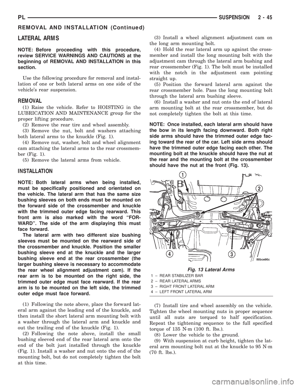
NOTE: Once installed, each lateral arm should have
the bow in its length facing downward. Both right
side arms should have the trimmed outer edge fac-
ing toward the rear of the car. Left side arms should
have the trimmed outer edge facing each other. The
mounting bolt at the knuckle should have the nut at
the rear and the mounting bolt at the crossmember
should have the nut at the front (Fig. 13).
(7) Install tire and wheel assembly on the vehicle.
Tighten the wheel mounting nuts in proper sequence
until all nuts are torqued to half specification.
Repeat the tightening sequence to the full specified
torque of 135 N´m (100 ft. lbs.).
(8) Lower the vehicle to the ground.
(9) With suspension at curb height, tighten the lat-
eral arm mounting bolt nut at the knuckle to 95 N´m
(70 ft. lbs.).
Fig. 13 Lateral Arms
1 ± REAR STABILIZER BAR
2 ± REAR LATERAL ARMS
3 ± RIGHT FRONT LATERAL ARM
4 ± LEFT FRONT LATERAL ARM
PLSUSPENSION 2 - 45
REMOVAL AND INSTALLATION (Continued)
Page 62 of 1285
DIFFERENTIAL AND DRIVELINE
TABLE OF CONTENTS
page page
DESCRIPTION AND OPERATION
FRONT DRIVESHAFTS.....................1
DIAGNOSIS AND TESTING
DRIVESHAFT DIAGNOSIS...................2
REMOVAL AND INSTALLATION
DRIVESHAFTS...........................3
DISASSEMBLY AND ASSEMBLY
DRIVESHAFT RECONDITION................7INNER TRIPOD JOINT SEAL BOOT...........7
OUTER C/V JOINT SEAL BOOT.............13
SPECIFICATIONS
TORQUE...............................17
SPECIAL TOOLS
DRIVESHAFT............................17
DESCRIPTION AND OPERATION
FRONT DRIVESHAFTS
Vehicles equipped with either an automatic or
manual transmission use an unequal±length drive-
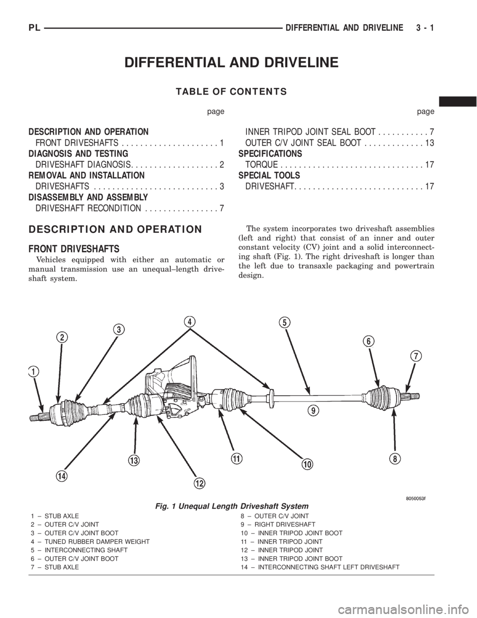
shaft system.The system incorporates two driveshaft assemblies
(left and right) that consist of an inner and outer
constant velocity (CV) joint and a solid interconnect-
ing shaft (Fig. 1). The right driveshaft is longer than
the left due to transaxle packaging and powertrain
design.
Fig. 1 Unequal Length Driveshaft System
1 ± STUB AXLE
2 ± OUTER C/V JOINT
3 ± OUTER C/V JOINT BOOT
4 ± TUNED RUBBER DAMPER WEIGHT
5 ± INTERCONNECTING SHAFT
6 ± OUTER C/V JOINT BOOT
7 ± STUB AXLE8 ± OUTER C/V JOINT
9 ± RIGHT DRIVESHAFT
10 ± INNER TRIPOD JOINT BOOT
11 ± INNER TRIPOD JOINT
12 ± INNER TRIPOD JOINT
13 ± INNER TRIPOD JOINT BOOT
14 ± INTERCONNECTING SHAFT LEFT DRIVESHAFT
PLDIFFERENTIAL AND DRIVELINE 3 - 1
Page 63 of 1285
Driveshafts used on both the right and left sides of
the vehicle use a tuned rubber damper weight
mounted to the interconnecting shaft (Fig. 1). The
damper weight applications vary by which side of the
vehicle the driveshaft is located on and the transmis-
sion application of the vehicle. When replacing a
driveshaft, be sure the replacement driveshaft has
the same damper weight as the original.
Both driveshaft assemblies use the same type of
inner and outer joints. The inner joint of both drive-
shaft assemblies is a tripod joint, and the outer joint
of both driveshaft assemblies is a Rzeppa joint. Both
tripod joints and Rzeppa joints are true constant
velocity (C/V) joint assemblies. The inner tripod joint
allows for the changes in driveshaft length through
the jounce and rebound travel of the front suspen-
sion.
On vehicles equipped with ABS brakes, the outer
C/V joint is equipped with a tone wheel used to
determine vehicle speed for ABS brake operation.
The inner tripod joint of both driveshafts is splined
into the transaxle side gears. The inner tripod joints
are retained in the side gears of the transaxle using
a snap ring located in the stub shaft of the tripod
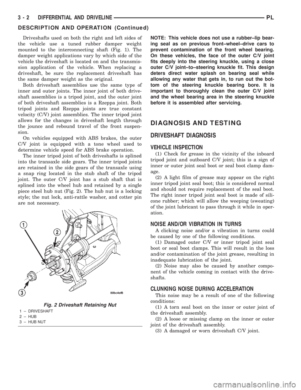
joint. The outer C/V joint has a stub shaft that is
splined into the wheel hub and retained by a single
piece steel hub nut (Fig. 2). The hub nut is a locking
style; the nut lock, anti-rattle washer, and cotter pin
are not necessary.NOTE: This vehicle does not use a rubber±lip bear-
ing seal as on previous front±wheel±drive cars to
prevent contamination of the front wheel bearing.
On these vehicles, the face of the outer C/V joint
fits deeply into the steering knuckle, using a close
outer C/V joint±to±steering knuckle fit. This design
deters direct water splash on bearing seal while
allowing any water that gets in, to run out the bot-
tom of the steering knuckle bearing bore. It is
important to thoroughly clean the outer C/V joint
and the wheel bearing area in the steering knuckle
before it is assembled after servicing.
DIAGNOSIS AND TESTING
DRIVESHAFT DIAGNOSIS
VEHICLE INSPECTION
(1) Check for grease in the vicinity of the inboard
tripod joint and outboard C/V joint; this is a sign of
inner or outer joint seal boot or seal boot clamp dam-
age.
(2) A light film of grease may appear on the right
inner tripod joint seal boot; this is considered normal
and should not require replacement of the seal boot.
The right inner tripod joint seal boot is made of sili-
cone rubber; which will allow the weeping (sweating)
of the joint lubricant to pass through it while in oper-
ation.
NOISE AND/OR VIBRATION IN TURNS
A clicking noise and/or a vibration in turns could
be caused by one of the following conditions.
(1) Damaged outer C/V or inner tripod joint seal
boot or seal boot clamps. This will result in the loss
and/or contamination of the joint grease, resulting in
inadequate lubrication of the joint.
(2) Noise may also be caused by another compo-
nent of the vehicle coming in contact with the drive-
shafts.
CLUNKING NOISE DURING ACCELERATION
This noise may be a result of one of the following
conditions:
(1) A torn seal boot on the inner or outer joint of
the driveshaft assembly.
(2) A loose or missing clamp on the inner or outer
joint of the driveshaft assembly.
(3) A damaged or worn driveshaft C/V joint.
Fig. 2 Driveshaft Retaining Nut
1 ± DRIVESHAFT
2 ± HUB
3 ± HUB NUT
3 - 2 DIFFERENTIAL AND DRIVELINEPL
DESCRIPTION AND OPERATION (Continued)
Page 73 of 1285
CAUTION: When venting the inner tripod joint
assembly, use care so inner tripod sealing boot
does not get punctured or, in any other way, dam-
aged. If sealing boot is punctured or damaged while
being vented, the sealing boot can not be used.
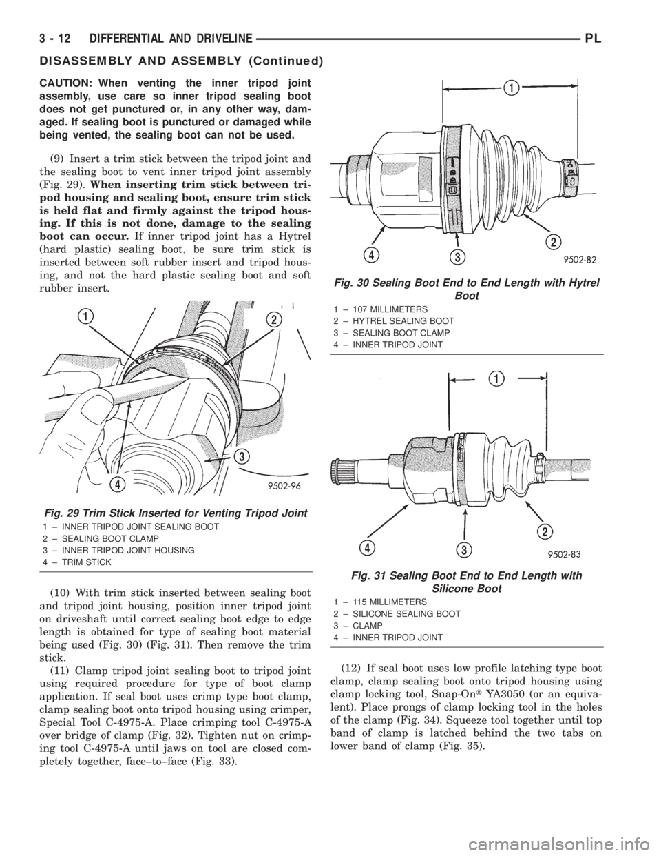
(9) Insert a trim stick between the tripod joint and
the sealing boot to vent inner tripod joint assembly
(Fig. 29).When inserting trim stick between tri-
pod housing and sealing boot, ensure trim stick
is held flat and firmly against the tripod hous-
ing. If this is not done, damage to the sealing
boot can occur.If inner tripod joint has a Hytrel
(hard plastic) sealing boot, be sure trim stick is
inserted between soft rubber insert and tripod hous-
ing, and not the hard plastic sealing boot and soft
rubber insert.
(10) With trim stick inserted between sealing boot
and tripod joint housing, position inner tripod joint
on driveshaft until correct sealing boot edge to edge
length is obtained for type of sealing boot material
being used (Fig. 30) (Fig. 31). Then remove the trim
stick.
(11) Clamp tripod joint sealing boot to tripod joint
using required procedure for type of boot clamp
application. If seal boot uses crimp type boot clamp,
clamp sealing boot onto tripod housing using crimper,
Special Tool C-4975-A. Place crimping tool C-4975-A
over bridge of clamp (Fig. 32). Tighten nut on crimp-
ing tool C-4975-A until jaws on tool are closed com-
pletely together, face±to±face (Fig. 33).(12) If seal boot uses low profile latching type boot
clamp, clamp sealing boot onto tripod housing using
clamp locking tool, Snap-OntYA3050 (or an equiva-
lent). Place prongs of clamp locking tool in the holes
of the clamp (Fig. 34). Squeeze tool together until top
band of clamp is latched behind the two tabs on
lower band of clamp (Fig. 35).
Fig. 29 Trim Stick Inserted for Venting Tripod Joint
1 ± INNER TRIPOD JOINT SEALING BOOT
2 ± SEALING BOOT CLAMP
3 ± INNER TRIPOD JOINT HOUSING
4 ± TRIM STICK
Fig. 30 Sealing Boot End to End Length with Hytrel
Boot
1 ± 107 MILLIMETERS
2 ± HYTREL SEALING BOOT
3 ± SEALING BOOT CLAMP
4 ± INNER TRIPOD JOINT
Fig. 31 Sealing Boot End to End Length with
Silicone Boot
1 ± 115 MILLIMETERS
2 ± SILICONE SEALING BOOT
3 ± CLAMP
4 ± INNER TRIPOD JOINT
3 - 12 DIFFERENTIAL AND DRIVELINEPL
DISASSEMBLY AND ASSEMBLY (Continued)
Page 98 of 1285
(2) Attach Bleeder Tank, Special Tool C-3496-B, or
an equivalent, to the adapter on the master cylinder.
(3) Attach a clear plastic hose to the bleeder screw
and feed the hose into a clear jar containing enough
fresh brake fluid to submerge the end of the hose
(Fig. 26).
(4) Open the bleeder screw at least one full turn or
more to obtain a steady stream of brake fluid.
(5) After approximately 4±8 ounces of fluid have
been bled through the brake circuit and an air-free
flow is maintained in the clear plastic hose and jar,
close the bleeder screw.
(6) Repeat this procedure at all the remaining
bleeder screws.
(7) Check the brake pedal travel. If pedal travel is
excessive or has not been improved, some air may
still be trapped in the system. Rebleed the brakes as
necessary.
(8) Test drive the vehicle to verify the brakes are
operating properly and pedal feel is correct.
MASTER CYLINDER BLEEDING
(1) Clamp the master cylinder in a vise.
(2) Attach four Master Cylinder Bleed Tubes, Spe-
cial Tool 8358-1, to the four ports of the master cyl-
inder and tighten each in place (Fig. 28). The bleed
tubes for the ports pertaining to the rear brakes are
made to attach to the proportioning valves screwed
into the master cylinder. Position the other end of
the tubes into the master cylinder reservoir so their
outlets are below the surface of the brake fluid in the
reservoir when filled.
(3) Fill the brake fluid reservoir with Mopart
brake fluid, or an equivalent conforming to DOT 3
specifications.
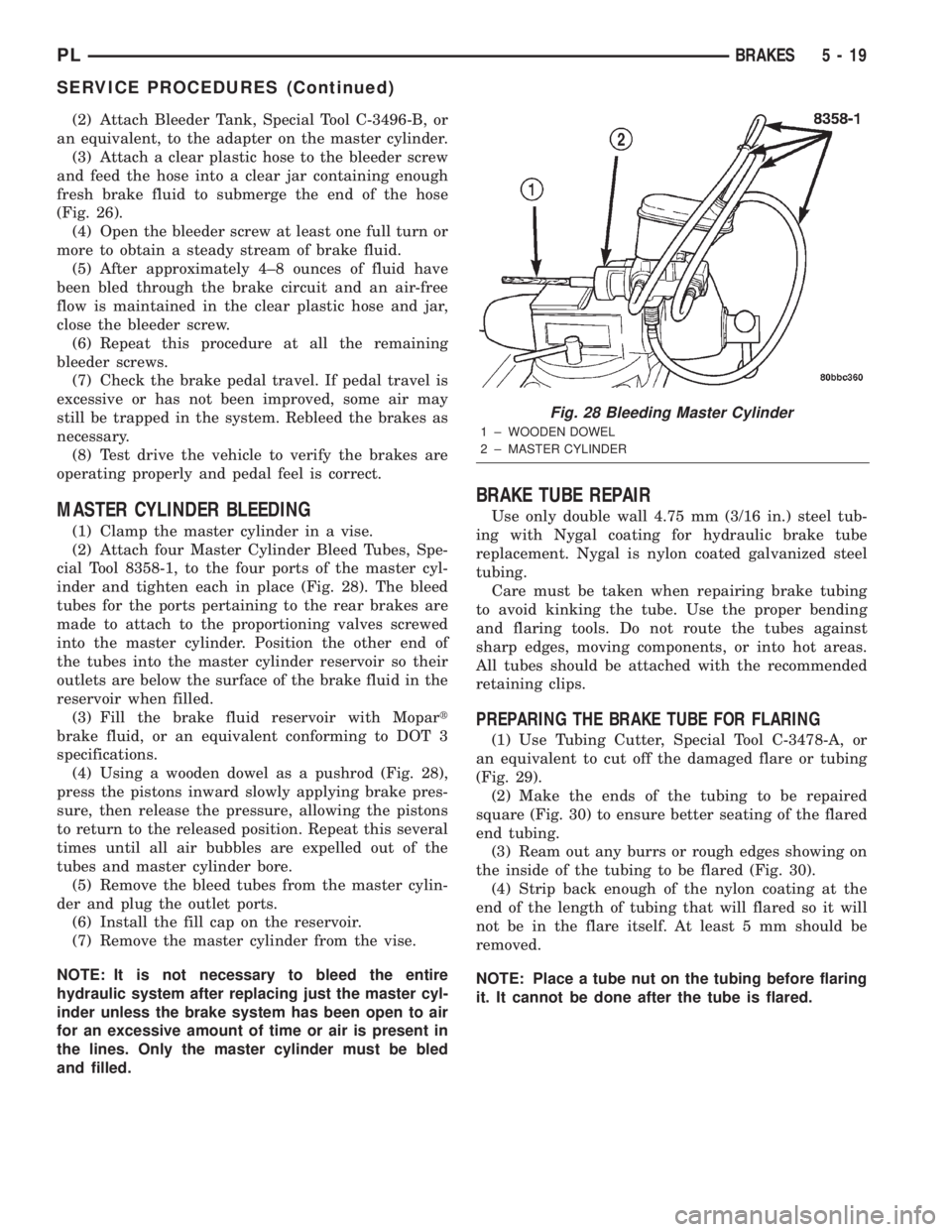
(4) Using a wooden dowel as a pushrod (Fig. 28),
press the pistons inward slowly applying brake pres-
sure, then release the pressure, allowing the pistons
to return to the released position. Repeat this several
times until all air bubbles are expelled out of the
tubes and master cylinder bore.
(5) Remove the bleed tubes from the master cylin-
der and plug the outlet ports.
(6) Install the fill cap on the reservoir.
(7) Remove the master cylinder from the vise.
NOTE: It is not necessary to bleed the entire
hydraulic system after replacing just the master cyl-
inder unless the brake system has been open to air
for an excessive amount of time or air is present in
the lines. Only the master cylinder must be bled
and filled.
BRAKE TUBE REPAIR
Use only double wall 4.75 mm (3/16 in.) steel tub-
ing with Nygal coating for hydraulic brake tube
replacement. Nygal is nylon coated galvanized steel
tubing.
Care must be taken when repairing brake tubing
to avoid kinking the tube. Use the proper bending
and flaring tools. Do not route the tubes against
sharp edges, moving components, or into hot areas.
All tubes should be attached with the recommended
retaining clips.
PREPARING THE BRAKE TUBE FOR FLARING
(1) Use Tubing Cutter, Special Tool C-3478-A, or
an equivalent to cut off the damaged flare or tubing
(Fig. 29).
(2) Make the ends of the tubing to be repaired
square (Fig. 30) to ensure better seating of the flared
end tubing.
(3) Ream out any burrs or rough edges showing on
the inside of the tubing to be flared (Fig. 30).
(4) Strip back enough of the nylon coating at the
end of the length of tubing that will flared so it will
not be in the flare itself. At least 5 mm should be
removed.
NOTE: Place a tube nut on the tubing before flaring
it. It cannot be done after the tube is flared.
Fig. 28 Bleeding Master Cylinder
1 ± WOODEN DOWEL
2 ± MASTER CYLINDER
PLBRAKES 5 - 19
SERVICE PROCEDURES (Continued)
Page 112 of 1285
INSTALLATION
(1) Lubricate the O-ring on the proportioning
valve. Make sure the O-ring on the proportioning
valve is new.
(2) Install the proportioning valve in its master
cylinder port. Tighten the proportioning valve to a
torque of 40 N´m (30 ft. lbs.).
(3) Connect the brake tube to the proportioning
valve (Fig. 54). Tighten the tube nut to a torque of 17
N´m (145 in. lbs.).
(4) Remove the brake pedal holder (Fig. 53).
(5) Bleed the affected brake line. See BASE
BRAKE BLEEDING in the SERVICE PROCE-
DURES section in this service manual group.
(6) Road test the vehicle to ensure proper opera-
tion of the brakes.
BRAKES TUBES AND HOSES
NOTE: Brake hoses for each brake are unique and
are not interchangeable.
Always use Mopartreplacement brake hoses to
ensure quality, correct length and superior fatigue
life. Care should be taken to make sure that the tube
and hose mating surfaces are clean and free from
nicks and burrs.
Use new copper seal washers on all connections
using banjo bolts and tighten all the fittings to their
specified torques.
Follow the procedures in the next three paragraphs
to reduce the potential for twisting the brake hose
during installation.
The flexible front hydraulic brake hose should
always be installed on the vehicle by first attaching
the banjo fitting to the disc brake caliper. Attach the
hose to the brake tubing before attaching it to the
front frame rail. Tighten all brake line fittings to the
specified torque.
On vehicles equipped with rear drum brakes,
loosely install the rear brake hose to the wheel cylin-
der first, then bolt the intermediate routing bracket
to the strut. Next, loosely install the hose to the steel
tube coming from the master cylinder. Attach the
hose bracket to the body. Finally, tighten the tube
nuts at each end of the brake hose.
On vehicles equipped with rear disc brakes, attach
the brake hose banjo fitting to the caliper first, then
loosely install the hose to the steel tube coming from
the master cylinder. Next, attach the brake hose
bracket to the body. Finally, tighten the tube nut at
the each of the end of the brake hose connecting to
the steel tube coming from the master cylinder.Only double wall 4.75 mm (3/16 in.) steel brake
line tubing with Nygal coating should be used for
replacement along with its special tube nuts. Care
must be taken when replacing brake tubing; to be
sure, use the proper bending and flaring tools, and
procedures to avoid kinking. Do not route the tubes
against sharp edges, moving components, or into hot
areas. All tubes should be properly attached with the
recommended retaining clips.
DISC BRAKE CALIPER (FRONT)
NOTE: Before proceeding with this procedure,
review SERVICE WARNINGS AND CAUTIONS at the
beginning of REMOVAL AND INSTALLATION in this
section.
REMOVAL
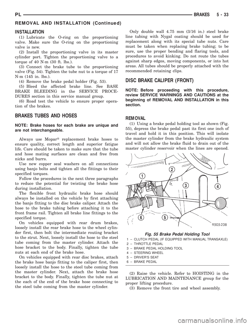
(1) Using a brake pedal holding tool as shown (Fig.
55), depress the brake pedal past its first one inch of
travel and hold it in this position. This will isolate
the master cylinder from the brake hydraulic system
and will not allow the brake fluid to drain out of the
master cylinder reservoir when the lines are opened.
(2) Raise the vehicle. Refer to HOISTING in the
LUBRICATION AND MAINTENANCE group for the
proper lifting procedure.
(3) Remove the front tire and wheel assembly.
Fig. 55 Brake Pedal Holding Tool
1 ± CLUTCH PEDAL (IF EQUIPPED WITH MANUAL TRANSAXLE)
2 ± THROTTLE PEDAL
3 ± BRAKE PEDAL HOLDING TOOL
4 ± STEERING WHEEL
5 ± DRIVER'S SEAT
6 ± BRAKE PEDAL
PLBRAKES 5 - 33
REMOVAL AND INSTALLATION (Continued)
Page 132 of 1285
(22) Install the center console and its mounting
screws.
(23) Remove the blocks from the tires and wheels.
PARKING BRAKE SHOES (REAR DISC BRAKE)
NOTE: Before proceeding with this procedure,
review SERVICE WARNINGS AND CAUTIONS at the
beginning of REMOVAL AND INSTALLATION in this
section.
REMOVAL
(1) Raise the vehicle. Refer to HOISTING in the
LUBRICATION AND MAINTENANCE group for the
proper lifting procedure.
(2) Remove the rear tire and wheel assembly.
(3) Remove the rear disc brake caliper assembly
from the brake rotor and store it out of the way.
Refer to DISC BRAKE SHOES (REAR) in this
REMOVAL AND INSTALLATION section of this ser-
vice manual group.
(4) Remove rear brake rotor.
(5) Remove the dust cap from the rear hub and
bearing.
(6) Remove the rear hub and bearing assembly
retaining nut and washer.
(7) Remove the rear hub and bearing assembly
from the rear spindle.
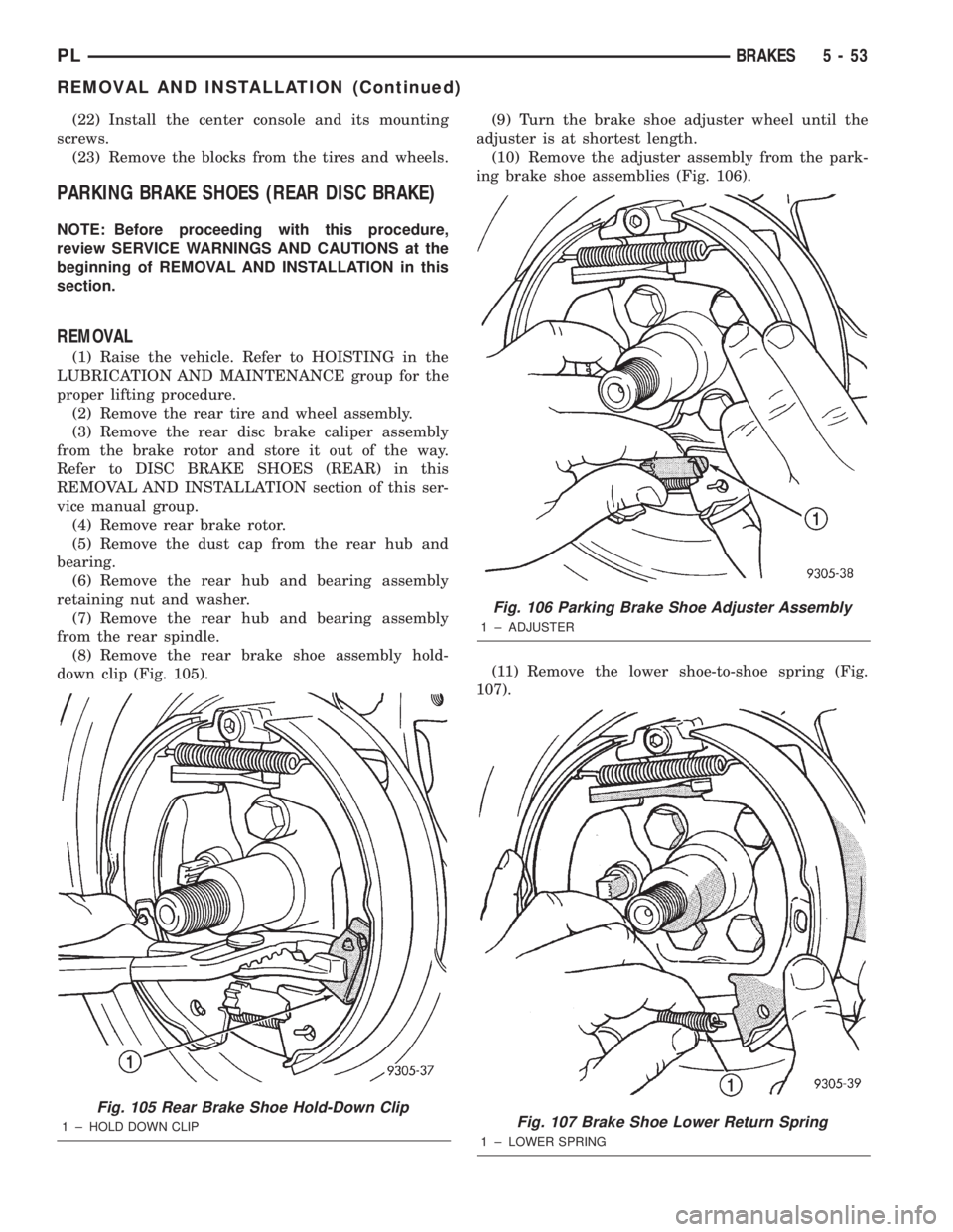
(8) Remove the rear brake shoe assembly hold-
down clip (Fig. 105).(9) Turn the brake shoe adjuster wheel until the
adjuster is at shortest length.
(10) Remove the adjuster assembly from the park-
ing brake shoe assemblies (Fig. 106).
(11) Remove the lower shoe-to-shoe spring (Fig.
107).
Fig. 105 Rear Brake Shoe Hold-Down Clip
1 ± HOLD DOWN CLIP
Fig. 106 Parking Brake Shoe Adjuster Assembly
1 ± ADJUSTER
Fig. 107 Brake Shoe Lower Return Spring
1 ± LOWER SPRING
PLBRAKES 5 - 53
REMOVAL AND INSTALLATION (Continued)
Page 134 of 1285
(14) Adjust the parking brake shoes as necessary.
Refer to ADJUSTMENTS in this section of this ser-
vice manual group.
(15) Lower the vehicle.
DISASSEMBLY AND ASSEMBLY
DISC BRAKE CALIPER (FRONT AND REAR)
Before disassembling the brake caliper, clean and
inspect it. Refer to CLEANING AND INSPECTION
in this section of this service manual group.
CALIPER GUIDE PIN BUSHING
REMOVAL
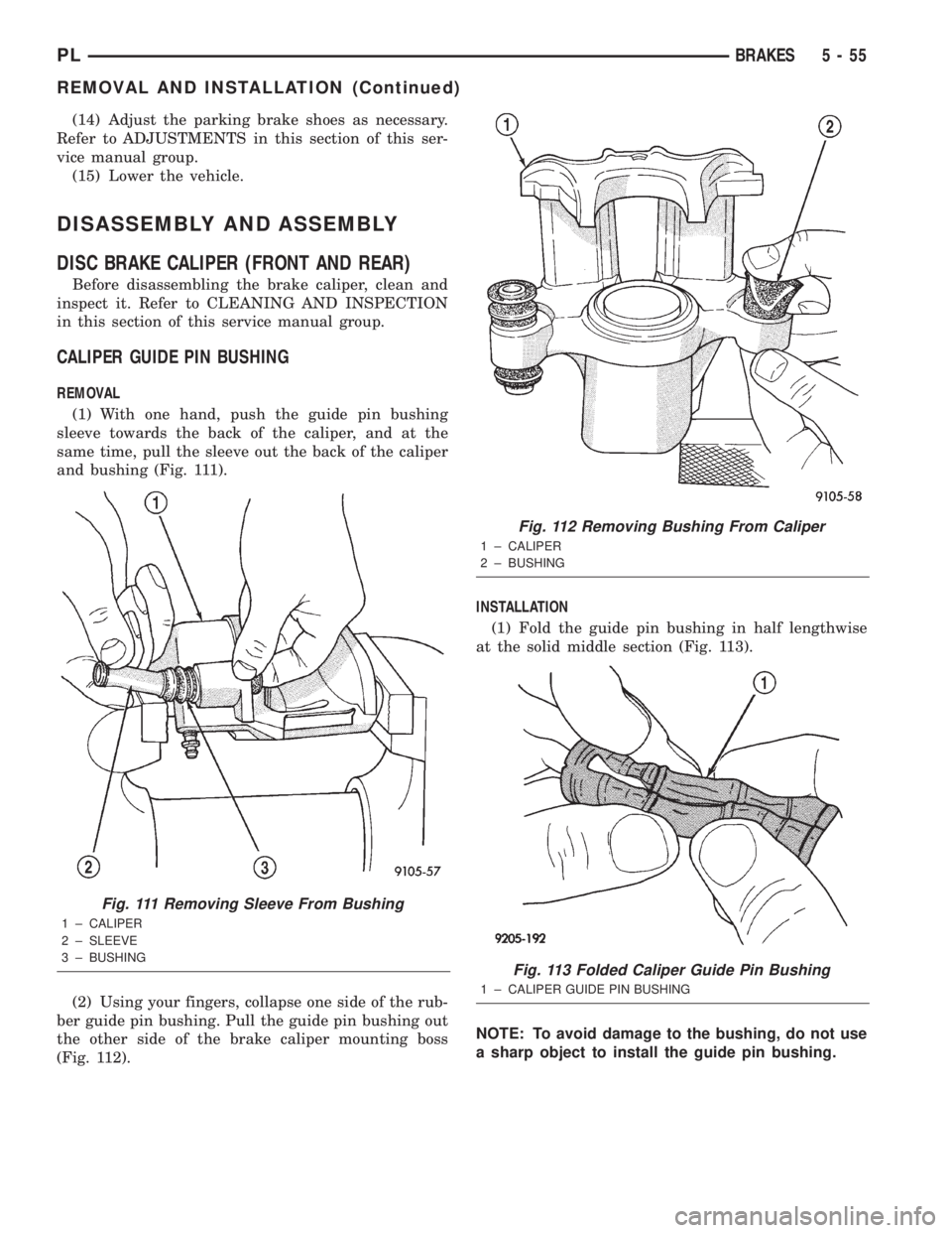
(1) With one hand, push the guide pin bushing
sleeve towards the back of the caliper, and at the
same time, pull the sleeve out the back of the caliper
and bushing (Fig. 111).
(2) Using your fingers, collapse one side of the rub-
ber guide pin bushing. Pull the guide pin bushing out
the other side of the brake caliper mounting boss
(Fig. 112).INSTALLATION
(1) Fold the guide pin bushing in half lengthwise
at the solid middle section (Fig. 113).
NOTE: To avoid damage to the bushing, do not use
a sharp object to install the guide pin bushing.
Fig. 111 Removing Sleeve From Bushing
1 ± CALIPER
2 ± SLEEVE
3 ± BUSHING
Fig. 112 Removing Bushing From Caliper
1 ± CALIPER
2 ± BUSHING
Fig. 113 Folded Caliper Guide Pin Bushing
1 ± CALIPER GUIDE PIN BUSHING
PLBRAKES 5 - 55
REMOVAL AND INSTALLATION (Continued)
Page 181 of 1285
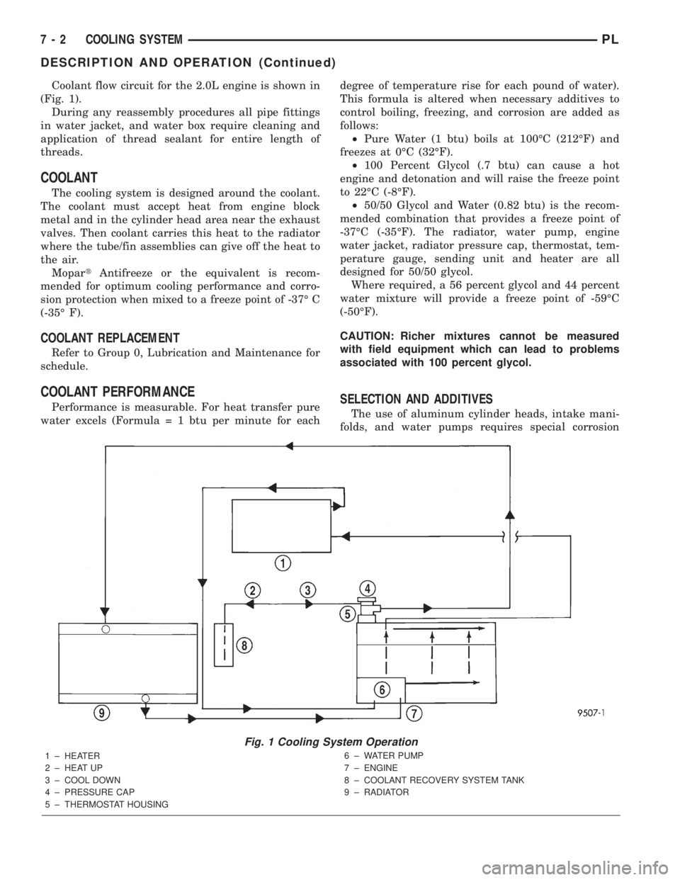
Coolant flow circuit for the 2.0L engine is shown in
(Fig. 1).
During any reassembly procedures all pipe fittings
in water jacket, and water box require cleaning and
application of thread sealant for entire length of
threads.
COOLANT
The cooling system is designed around the coolant.
The coolant must accept heat from engine block
metal and in the cylinder head area near the exhaust
valves. Then coolant carries this heat to the radiator
where the tube/fin assemblies can give off the heat to
the air.
MopartAntifreeze or the equivalent is recom-
mended for optimum cooling performance and corro-
sion protection when mixed to a freeze point of -37É C
(-35É F).
COOLANT REPLACEMENT
Refer to Group 0, Lubrication and Maintenance for
schedule.
COOLANT PERFORMANCE
Performance is measurable. For heat transfer pure
water excels (Formula = 1 btu per minute for eachdegree of temperature rise for each pound of water).
This formula is altered when necessary additives to
control boiling, freezing, and corrosion are added as
follows:
²Pure Water (1 btu) boils at 100ÉC (212ÉF) and
freezes at 0ÉC (32ÉF).
²100 Percent Glycol (.7 btu) can cause a hot
engine and detonation and will raise the freeze point
to 22ÉC (-8ÉF).
²50/50 Glycol and Water (0.82 btu) is the recom-
mended combination that provides a freeze point of
-37ÉC (-35ÉF). The radiator, water pump, engine
water jacket, radiator pressure cap, thermostat, tem-
perature gauge, sending unit and heater are all
designed for 50/50 glycol.
Where required, a 56 percent glycol and 44 percent
water mixture will provide a freeze point of -59ÉC
(-50ÉF).
CAUTION: Richer mixtures cannot be measured
with field equipment which can lead to problems
associated with 100 percent glycol.SELECTION AND ADDITIVES
The use of aluminum cylinder heads, intake mani-
folds, and water pumps requires special corrosion
Fig. 1 Cooling System Operation
1 ± HEATER
2 ± HEAT UP
3 ± COOL DOWN
4 ± PRESSURE CAP
5 ± THERMOSTAT HOUSING6 ± WATER PUMP
7 ± ENGINE
8 ± COOLANT RECOVERY SYSTEM TANK
9 ± RADIATOR
7 - 2 COOLING SYSTEMPL
DESCRIPTION AND OPERATION (Continued)