transmission fluid DODGE NEON 2000 Service Repair Manual
[x] Cancel search | Manufacturer: DODGE, Model Year: 2000, Model line: NEON, Model: DODGE NEON 2000Pages: 1285, PDF Size: 29.42 MB
Page 4 of 1285
MAINTENANCE SCHEDULES
TABLE OF CONTENTS
page page
DESCRIPTION AND OPERATION
MAINTENANCE SCHEDULES................3
SPECIFICATIONS
UNSCHEDULED INSPECTION................3SCHEDULE ± A...........................3
SCHEDULE ± B...........................4
DESCRIPTION AND OPERATION
MAINTENANCE SCHEDULES
There are two maintenance schedules that show
proper service for your vehicle.
First is Schedule ±A. It lists all the scheduled
maintenance to be performed under ªnormalº operat-
ing conditions.
Second is Schedule ±B. It is a schedule for vehi-
cles that are operated under the following conditions:
²Frequent short trip driving less than 5 miles (8
km)
²Frequent driving in dusty conditions
²Extensive idling
²More than 50% of the driving is at sustained
high speeds during hot weather, above 90É F (32É C)
SPECIFICATIONS
UNSCHEDULED INSPECTION
At Each Stop For Fuel
²Check engine oil level and add as required.
²Check windshield washer solvent and add as
required.
Once A Month
²Check tire pressure and look for unusual wear
or damage.
²Inspect the battery and clean and tighten termi-
nals as required.
²Check fluid levels of coolant reservoir, brake
master cylinder, power steering and transmission.
Add fluid as required.
²Check all lights and all other electrical items for
correct operation.
At Each Oil Change
²Inspect the exhaust system.
²Inspect brake hoses.
²Inspect the CV joints and front suspension com-
ponent boots and seals.²Rotate the tires at each oil change interval
shown on Schedule ± A (7,500 miles - 12 000 km) or
every other interval on Schedule ± B (6,000 miles -
10 000 km).
²Check the engine coolant level, hoses, and
clamps.
If mileage is less than 7,500 miles (12 000 km)
yearly, replace the engine oil filter at each oil change.
EMISSION CONTROL SYSTEM MAINTENANCE
The scheduled emission maintenance listed inbold
typeon the Maintenance Schedules, must be done at
the mileage specified to assure the continued proper
functioning of the emission control system. These,
and all other maintenance services included in this
manual, should be done to provide the best vehicle
performance and reliability. More frequent mainte-
nance may be needed for vehicles in severe operating
conditions such as dusty areas and very short trip
driving.
FLUID FILL POINTS AND LUBRICATION
LOCATIONS
The fluid fill/check locations and lubrication loca-
tions are located in each applicable group.
SCHEDULE ± A
7,500 Miles (12 000 km) or at 6 months
²Change the engine oil.
²Replace the engine oil filter.
15,000 Miles (24 000 km) or at 12 months
²Change the engine oil.
²Replace the engine oil filter.
²Adjust the drive belt tension.
22,500 Miles (36 000 km) or at 18 months
²Change the engine oil.
²Replace the engine oil filter.
²Inspect the front brake pads and rear brake lin-
ings.
PLLUBRICATION AND MAINTENANCE 0 - 3
Page 8 of 1285
JUMP STARTING, TOWING, AND HOISTING
TABLE OF CONTENTS
page page
DESCRIPTION AND OPERATION
JUMP STARTING PROCEDURE...............7
TOWING RECOMMENDATIONS...............7
HOISTING RECOMMENDATIONS.............7SERVICE PROCEDURES
JUMP STARTING PROCEDURE...............7
TOWING RECOMMENDATIONS...............8
HOISTING RECOMMENDATIONS.............9
DESCRIPTION AND OPERATION
JUMP STARTING PROCEDURE
Describes the procedure for starting a disable vehi-
cle.
TOWING RECOMMENDATIONS
Describes the recommended towing procedures.
HOISTING RECOMMENDATIONS
Describes the location of hoisting and jacking
points so that the vehicle can be lifted by a floor jack
or hoist.
SERVICE PROCEDURES
JUMP STARTING PROCEDURE
WARNING: REVIEW ALL SAFETY PRECAUTIONS
AND WARNINGS IN GROUP 8A, BATTERY/START-
ING/CHARGING SYSTEMS DIAGNOSTICS. DO NOT
JUMP START A FROZEN BATTERY, PERSONAL
INJURY CAN RESULT. DO NOT JUMP START WHEN
MAINTENANCE FREE BATTERY INDICATOR DOT IS
YELLOW OR BRIGHT COLOR. DO NOT JUMP
START A VEHICLE WHEN THE BATTERY FLUID IS
BELOW THE TOP OF LEAD PLATES. DO NOT
ALLOW JUMPER CABLE CLAMPS TO TOUCH
EACH OTHER WHEN CONNECTED TO A BOOSTER
SOURCE. DO NOT USE OPEN FLAME NEAR BAT-
TERY. REMOVE METALLIC JEWELRY WORN ON
HANDS OR WRISTS TO AVOID INJURY BY ACCI-
DENTAL ARCING OF BATTERY CURRENT. WHEN
USING A HIGH OUTPUT BOOSTING DEVICE, DO
NOT ALLOW BATTERY VOLTAGE TO EXCEED 16
VOLTS. REFER TO INSTRUCTIONS PROVIDED
WITH DEVICE BEING USED.
CAUTION: When using another vehicle as a
booster, do not allow vehicles to touch. Electrical
systems can be damaged on either vehicle.
TO JUMP START A DISABLED VEHICLE:
(1) Raise hood on disabled vehicle and visually
inspect engine compartment for:
²Battery cable clamp condition, clean if necessary.
²Frozen battery.
²Yellow or bright color test indicator, if equipped.
²Low battery fluid level.
²Generator drive belt condition and tension.
²Fuel fumes or leakage, correct if necessary.
CAUTION: If the cause of starting problem on dis-
abled vehicle is severe, damage to booster vehicle
charging system can result.
(2) When using another vehicle as a booster
source, park the booster vehicle within cable reach.
Turn off all accessories, set the parking brake, place
the automatic transmission in PARK or the manual
transmission in NEUTRAL and turn the ignition
OFF.
(3) On disabled vehicle, place gear selector in park
or neutral and set park brake. Turn off all accesso-
ries.
(4) Connect jumper cables to booster battery. RED
clamp to positive terminal (+). BLACK clamp to neg-
ative terminal (-). DO NOT allow clamps at opposite
end of cables to touch, electrical arc will result.
Review all warnings in this procedure.
(5) On disabled vehicle, connect RED jumper cable
clamp to positive (+) terminal. Connect BLACK
jumper cable clamp to engine ground as close to the
ground cable attaching point as possible (Fig. 1).
(6) Start the engine in the vehicle which has the
booster battery, let the engine idle a few minutes,
then start the engine in the vehicle with the dis-
charged battery.
CAUTION: Do not crank starter motor on disabled
vehicle for more than 15 seconds, starter will over-
heat and could fail.
(7) Allow battery in disabled vehicle to charge to
at least 12.4 volts (75% charge) before attempting to
start engine. If engine does not start within 15 sec-
PLLUBRICATION AND MAINTENANCE 0 - 7
Page 142 of 1285
SPECIFICATIONS
BRAKE FLUID
The brake fluid used in this vehicle must conform
to DOT 3 specifications and SAE J1703 standards.
No other type of brake fluid is recommended or
approved for usage in the vehicle brake system. Use
only Mopar brake fluid or an equivalent from a
tightly sealed container.
CAUTION: Never use reclaimed brake fluid or fluid
from an container which has been left open. An
open container will absorb moisture from the air
and contaminate the fluid.
CAUTION: Never use any type of a petroleum-
based fluid in the brake hydraulic system. Use of
such type fluids will result in seal damage of the
vehicle brake hydraulic system causing a failure of
the vehicle brake system. Petroleum based fluids
would be items such as engine oil, transmission
fluid, power steering fluid, etc.
BRAKE ACTUATION SYSTEM
ACTUATION:
Vacuum Operated Power Brakes.....Standard
Hydraulic System.......Dual-Diagonally Split
BRAKE PEDAL:
Pedal Ratio..........................3.41
POWER BRAKE BOOSTER:
Make/Type..................Bosch/Vacuum
Mounting Studs.................. M8x1.25
Diaphragm Size/Type........ 205mmTandem
MASTER CYLINDER ASSEMBLY:
Type ........................Dual Tandem
Body Material...........Anodized Aluminum
Reservoir Material.............Polypropelene
MASTER CYLINDER BORE STROKE AND
SPLIT:
NonABS ..............22.23 mm x 34.0 mm
(0.875 in. x 1.34 in.)
ABS . . 23.82 mm x 34.0 mm (0.937 in. x 1.34 in.)
Displacement Split.................. 50/50MASTER CYLINDER FLUID OUTLET PORTS:
Tube Fitting Type...... SAE45ÉInverted Flare
W/ABS - Primary Tube Nut
Thread........................7/16 in.±24
W/ABS - Secondary Tube Nut
Thread........................ 3/8in.±24
W/O ABS - All Tube Nut Threads....7/16 in.±24
ABS HYDRAULIC CONTROL UNIT:
Hydraulic Tube Fitting
Type................ SAE45ÉInverted Flare
All Tube Nut Threads............7/16 in.±24
PROPORTIONING VALVE:
Material.......................Aluminum
Function.....Hydraulic Pressure Proportioning
BRAKE FASTENER TORQUE SPECIFICATIONS
DESCRIPTION TORQUE
BRAKE TUBES:
Tube Nuts............... 17N´m(145 in. lbs.)
MASTER CYLINDER:
Mounting Nuts.......... 28N´m(250 in. lbs.)
POWER BRAKE BOOSTER:
Mounting Nuts.......... 34N´m(300 in. lbs.)
DISC BRAKE CALIPER:
Caliper Banjo Bolt......... 48N´m(35ft.lbs.)
Guide Pin Bolts.......... 22N´m(192 in. lbs.)
Bleeder Screw........... 15N´m(125 in. lbs.)
WHEEL CYLINDER (REAR):
Mounting Bolts.......... 13N´m(115in.lbs.)
Bleeder Screw............ 10N´m(80in.lbs.)
DRUM BRAKE SHOE SUPPORT PLATE
(REAR):
Mounting Bolts........... 75N´m(55ft.lbs.)
DISC BRAKE ADAPTER (REAR):
Mounting Bolts........... 75N´m(55ft.lbs.)
HUB AND BEARING (REAR):
Retaining Nut.......... 217N´m(160 ft. lbs.)
PARKING BRAKE:
Lever Mounting Nuts..... 28N´m(250 in. lbs.)
TIRE AND WHEEL:
Wheel Mounting Nut...........109±150 N´m
(80±110 ft. lbs.)
INTEGRATED CONTROL UNIT:
Mounting Bolts........... 11N´m(97in.lbs.)
CAB Mounting bolts........ 2N´m(17in.lbs.)
Bracket-to-Frame Rail Bolts.......... 23N´m
(200 in. lbs.)
WHEEL SPEED SENSOR:
Head Mounting bolt...... 12N´m(105 in. lbs.)
PLBRAKES 5 - 63
Page 201 of 1285
(10) Radiator can now be lifted free from engine
compartment.Care should be taken not to dam-
age radiator cooling fins or water tubes during
removal.
INSTALLATION
(1) Slide radiator down into position behind radia-
tor support (yoke).
(2) Attach air conditioning condenser to radiator, if
equipped (Fig. 25), with four mounting screws.
Tighten screws to 5.4 N´m (50 in. lbs.). Then seat the
radiator assembly lower rubber isolators into the
mounting holes provided in the lower crossmember.
(3) Install and tighten radiator isolator mounting
bracket screws to 10 N´m (90 in. lbs.) (Fig. 24). The
radiator should have clearance to move up, approxi-
mately 5±8 mm (0.20±0.31 in.) after assembled.
(4) Install lower radiator hose. Align the hose and
position the clamp so it will not interfere with engine
components.
(5) Connect automatic transmission hoses, if
equipped. Tighten hose clamps to 2 N´m (18 in. lbs.).
(6) Slide fan module down into clip(s) on lower
radiator flange (Fig. 23). Install retaining screws and
tighten to 7.5 N´m (65 in. lbs.).
(7) Connect the cooling fan motor electrical connec-
tor.
(8) Install upper radiator hose. Align the hose and
position the clamp so they will not interfere with the
engine or the hood.
(9) Connect negative cable to battery.
(10) Fill cooling system with coolant. Refer to pro-
cedure in this section.
(11) Operate engine until it reaches normal operat-
ing temperature. Check cooling system and auto-
matic transmission for correct fluid levels.
RADIATOR DRAINCOCK
REMOVAL
(1) Turn the drain cock stem counterclockwise to
unscrew the stem. When the stem is unscrewed to
the end of the threads, pull the stem (Fig. 26) from
the radiator tank.
INSTALLATION
(1) Push the draincock assembly body into the
tank opening.
(2) Tighten the draincock stem by turning clock-
wise to 2.0-2.7 N´m (18-25 in. lbs.).
COOLING FAN MODULE
All models use a single speed electric motor driven
cooling system fan. The fan module includes a motor,
fan blade, and support shroud. The module is fas-
tened to the radiator by screws.
REMOVAL
WARNING: DO NOT REMOVE THE CYLINDER
BLOCK PLUG OR THE RADIATOR DRAINCOCK
WITH THE SYSTEM HOT AND UNDER PRESSURE
BECAUSE SERIOUS BURNS FROM COOLANT CAN
OCCUR.
(1) Disconnect negative cable from battery.
(2) Drain cooling system below upper radiator hose
level. Refer to procedure in this section.
(3) Remove upper radiator hose from radiator (Fig.
27).
(4) Disconnect fan module electrical connector.
(5) Remove fan module screws from radiator (Fig.
28).
(6) Lift fan shroud up and out of lower shroud
attachment clips.
(7) Refer to Disassembly and Assembly in this sec-
tion for fan module sub-component service proce-
dures.
Fig. 25 A/C Condenser to Radiator Mounting Screws
1 ± AIR CONDITIONING CONDENSER TO RADIATOR
MOUNTING SCREWS
2 ± LOWER ISOLATOR MOUNTS
Fig. 26 Draincock
1 ± DRAIN COCK BODY
2 ± DRAIN COCK HOUSING
7 - 22 COOLING SYSTEMPL
REMOVAL AND INSTALLATION (Continued)
Page 724 of 1285
ENGINE
TABLE OF CONTENTS
page page
STANDARD SERVICE PROCEDURES........... 1
ENGINE DIAGNOSIS........................ 82.0L SOHC ENGINE....................... 15
STANDARD SERVICE PROCEDURES
TABLE OF CONTENTS
page page
GENERAL INFORMATION
FORM-IN-PLACE GASKETS & SEALERS........1
ENGINE GASKET SURFACE PREPARATION.....2
CRANKSHAFT DAMPER BOLT ACCESS PLUG . . . 2
ENGINE CORE PLUGS.....................2
ENGINE PERFORMANCE...................3HONING CYLINDER BORES.................3
MEASURING WITH PLASTIGAGE.............4
REPAIR OF DAMAGED OR WORN THREADS....5
HYDROSTATIC LOCKED ENGINE.............5
CHECKING ENGINE OIL LEVEL..............6
ENGINE OIL SERVICE......................7
GENERAL INFORMATION
FORM-IN-PLACE GASKETS & SEALERS
There are numerous places where form-in-place
gaskets are used on the engine. Care must be taken
when applying form-in-place gaskets to assure
obtaining the desired results.Do not use form-in-
place gasket material unless specified.Bead size,
continuity, and location are of great importance. Too
thin a bead can result in leakage while too much can
result in spill-over which can break off and obstruct
fluid feed lines. A continuous bead of the proper
width is essential to obtain a leak-free gasket.
There are numerous types of form-in-place gasket
materials that are used in the engine area. Mopart
Engine RTV GEN II, MopartATF-RTV, and Mopart
Gasket Maker gasket materials, each have different
properties and can not be used in place of the other.
MOPARtENGINE RTV GEN II
MopartEngine RTV GEN II is used to seal com-
ponents exposed to engine oil. This material is a spe-
cially designed black silicone rubber RTV that
retains adhesion and sealing properties when
exposed to engine oil. Moisture in the air causes the
material to cure. This material is available in three
ounce tubes and has a shelf life of one year. After one
year this material will not properly cure. Alwaysinspect the package for the expiration date before
use.
MOPARtATF RTV
MopartATF RTV is a specifically designed black
silicone rubber RTV that retains adhesion and seal-
ing properties to seal components exposed to auto-
matic transmission fluid, engine coolants, and
moisture. This material is available in three ounce
tubes and has a shelf life of one year. After one year
this material will not properly cure. Always inspect
the package for the expiration date before use.
MOPARtGASKET MAKER
MopartGasket Maker is an anaerobic type gasket
material. The material cures in the absence of air
when squeezed between two metallic surfaces. It will
not cure if left in the uncovered tube. The anaerobic
material is for use between two machined surfaces.
Do not use on flexible metal flanges.
MOPARtBED PLATE SEALANT
MopartBed Plate Sealant is a unique (green-in-
color) anaerobic type gasket material that is specially
made to seal the area between the bedplate and cyl-
inder block without disturbing the bearing clearance
or alignment of these components. The material
cures slowly in the absence of air when torqued
between two metallic surfaces, and will rapidly cure
when heat is applied.
PLENGINE 9 - 1
Page 811 of 1285
CAUTION: After removing the steering knuckle from
the ball joint stud, do not pull outward on the knuckle.
Pulling the steering knuckle outward at this point can
separate the inner C/V joint on the driveshaft. Refer to
FRONT DRIVESHAFTS in the DIFFERENTIAL AND
DRIVELINE group for further information.
NOTE: Use caution when separating the ball joint
stud from the steering knuckle, so the ball joint seal
does not get cut.
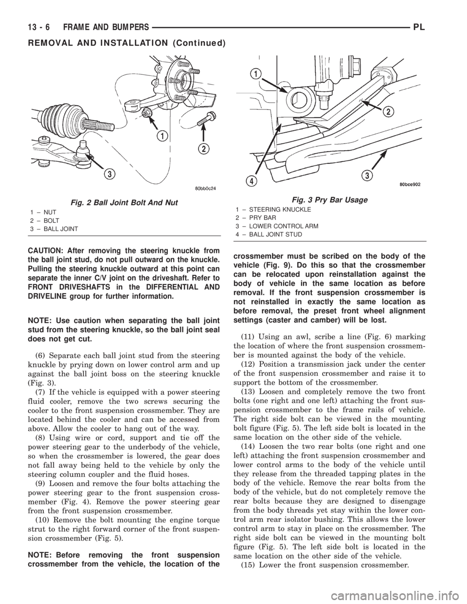
(6) Separate each ball joint stud from the steering
knuckle by prying down on lower control arm and up
against the ball joint boss on the steering knuckle
(Fig. 3).
(7) If the vehicle is equipped with a power steering
fluid cooler, remove the two screws securing the
cooler to the front suspension crossmember. They are
located behind the cooler and can be accessed from
above. Allow the cooler to hang out of the way.
(8) Using wire or cord, support and tie off the
power steering gear to the underbody of the vehicle,
so when the crossmember is lowered, the gear does
not fall away being held to the vehicle by only the
steering column coupler and the fluid hoses.
(9) Loosen and remove the four bolts attaching the
power steering gear to the front suspension cross-
member (Fig. 4). Remove the power steering gear
from the front suspension crossmember.
(10) Remove the bolt mounting the engine torque
strut to the right forward corner of the front suspen-
sion crossmember (Fig. 5).
NOTE: Before removing the front suspension
crossmember from the vehicle, the location of thecrossmember must be scribed on the body of the
vehicle (Fig. 9). Do this so that the crossmember
can be relocated upon reinstallation against the
body of vehicle in the same location as before
removal. If the front suspension crossmember is
not reinstalled in exactly the same location as
before removal, the preset front wheel alignment
settings (caster and camber) will be lost.
(11) Using an awl, scribe a line (Fig. 6) marking
the location of where the front suspension crossmem-
ber is mounted against the body of the vehicle.
(12) Position a transmission jack under the center
of the front suspension crossmember and raise it to
support the bottom of the crossmember.
(13) Loosen and completely remove the two front
bolts (one right and one left) attaching the front sus-
pension crossmember to the frame rails of vehicle.
The right side bolt can be viewed in the mounting
bolt figure (Fig. 5). The left side bolt is located in the
same location on the other side of the vehicle.
(14) Loosen the two rear bolts (one right and one
left) attaching the front suspension crossmember and
lower control arms to the body of the vehicle until
they release from the threaded tapping plates in the
body of the vehicle. Remove the rear bolts from the
body of the vehicle, but do not completely remove the
rear bolts because they are designed to disengage
from the body threads yet stay within the lower con-
trol arm rear isolator bushing. This allows the lower
control arm to stay in place on the crossmember. The
right side bolt can be viewed in the mounting bolt
figure (Fig. 5). The left side bolt is located in the
same location on the other side of the vehicle.
(15) Lower the front suspension crossmember.
Fig. 2 Ball Joint Bolt And Nut
1 ± NUT
2 ± BOLT
3 ± BALL JOINT
Fig. 3 Pry Bar Usage
1 ± STEERING KNUCKLE
2±PRYBAR
3 ± LOWER CONTROL ARM
4 ± BALL JOINT STUD
13 - 6 FRAME AND BUMPERSPL
REMOVAL AND INSTALLATION (Continued)
Page 888 of 1285
reduces the power required to drive the pump and
holds down temperature build-up.
When steering conditions exceed maximum pres-
sure requirements, such as when the wheels are
turned against the stops, the pressure built up in the
steering gear exerts pressure on the spring end of the
flow control valve. The high pressure lifts the relief
valve ball from its seat and allows oil to flow through
a trigger orifice located in the outlet fitting. This
reduces pressure on the spring end of the flow con-
trol valve which then opens and allows the oil to
return to the intake side of the pump. This action
limits maximum pressure output of the pump to a
safe level.
Under normal power steering pump operating con-
ditions, pressure requirements of the pump are below
maximum, causing the pressure relief valve to
remain closed.
POWER STEERING FLUID RESERVOIR
The power steering fluid reservoir is mounted on
the power steering pump using 3 bolts (Fig. 1). It
stores fluid for the power steering system.
The power steering fluid reservoir is considered an
integral part of the power steering pump and is not
serviced separately.
SERVICE PROCEDURES
POWER STEERING PUMP INITIAL OPERATION
CAUTION: The fluid level should be checked with
engine off to prevent injury from moving compo-
nents. Use only MoparTPower Steering Fluid. Do
not use automatic transmission fluid. Do not over-
fill.
Wipe the filler cap clean, then check the fluid level.
The dipstick should indicateCOLDwhen the fluid is
at normal temperature, approximately 21ÉC to 27ÉC
(70ÉF to 80ÉF).
(1) Fill the power steering fluid reservoir to the
proper level and let the fluid settle for at least two
minutes.
(2) Start the engine and let run for a few seconds,
then turn the engine off.
(3) Add fluid if necessary. Repeat the above proce-
dure until the fluid level remains constant after run-
ning the engine.
(4) Raise the front wheels off the ground.
(5) Start the engine. Slowly turn the steering
wheel right and left, lightly contacting the wheel
stops.
(6) Add power steering fluid if necessary.
(7) Lower the vehicle and turn the steering wheel
slowly from lock to lock.(8) Stop the engine. Check the fluid level and refill
as required.
(9) If the fluid is extremely foamy, allow the vehi-
cle to stand a few minutes and repeat the above pro-
cedure.
REMOVAL AND INSTALLATION
SERVICE WARNINGS AND CAUTIONS
WARNING: POWER STEERING FLUID, ENGINE
PARTS AND EXHAUST SYSTEM MAY BE
EXTREMELY HOT IF ENGINE HAS BEEN RUNNING.
DO NOT START ENGINE WITH ANY LOOSE OR DIS-
CONNECTED HOSES. DO NOT ALLOW HOSES TO
TOUCH HOT EXHAUST MANIFOLD OR CATALYST.
WARNING: FLUID LEVEL SHOULD BE CHECKED
WITH THE ENGINE OFF TO PREVENT PERSONAL
INJURY FROM MOVING PARTS.
CAUTION: When the system is open, cap all open
ends of the hoses, power steering pump fittings or
power steering gear ports to prevent entry of for-
eign material into the components.
NOTE: Do not use any type of automatic transmis-
sion fluid in the power steering system.
POWER STEERING PUMP
NOTE: Before proceeding with this removal and
installation procedure, review SERVICE WARNINGS
AND CAUTIONS at the beginning of REMOVAL AND
INSTALLATION in this section.
REMOVAL
(1) Remove battery cable from the negative post on
the battery.
(2) Siphon as much fluid as possible from the
power steering fluid reservoir.
(3) Remove the power steering pump drive belt
from the power steering pump pulley. Refer to
ACCESSORY DRIVE BELTS in the COOLING SYS-
TEM service manual group for the required removal
and installation procedure.
(4) Remove the hose clamp securing the return
hose to the power steering fluid reservoir. Slide the
hose off the end of the reservoir fitting. (Fig. 2).
(5) Back out the tube nut securing the power
steering fluid pressure hose to the power steering
pump and remove the hose from the pump (Fig. 2).
PLSTEERING 19 - 17
DESCRIPTION AND OPERATION (Continued)
Page 895 of 1285
(13) If the vehicle is equipped with a power steer-
ing fluid cooler, remove the two screws securing the
cooler to the front suspension crossmember. They are
located behind the cooler and can be accessed from
above. Allow the cooler to hang out of the way.
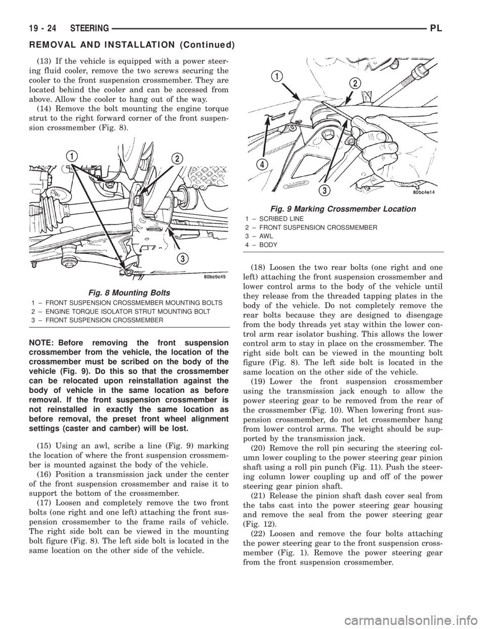
(14) Remove the bolt mounting the engine torque
strut to the right forward corner of the front suspen-
sion crossmember (Fig. 8).
NOTE: Before removing the front suspension
crossmember from the vehicle, the location of the
crossmember must be scribed on the body of the
vehicle (Fig. 9). Do this so that the crossmember
can be relocated upon reinstallation against the
body of vehicle in the same location as before
removal. If the front suspension crossmember is
not reinstalled in exactly the same location as
before removal, the preset front wheel alignment
settings (caster and camber) will be lost.
(15) Using an awl, scribe a line (Fig. 9) marking
the location of where the front suspension crossmem-
ber is mounted against the body of the vehicle.
(16) Position a transmission jack under the center
of the front suspension crossmember and raise it to
support the bottom of the crossmember.
(17) Loosen and completely remove the two front
bolts (one right and one left) attaching the front sus-
pension crossmember to the frame rails of vehicle.
The right side bolt can be viewed in the mounting
bolt figure (Fig. 8). The left side bolt is located in the
same location on the other side of the vehicle.(18) Loosen the two rear bolts (one right and one
left) attaching the front suspension crossmember and
lower control arms to the body of the vehicle until
they release from the threaded tapping plates in the
body of the vehicle. Do not completely remove the
rear bolts because they are designed to disengage
from the body threads yet stay within the lower con-
trol arm rear isolator bushing. This allows the lower
control arm to stay in place on the crossmember. The
right side bolt can be viewed in the mounting bolt
figure (Fig. 8). The left side bolt is located in the
same location on the other side of the vehicle.
(19) Lower the front suspension crossmember
using the transmission jack enough to allow the
power steering gear to be removed from the rear of
the crossmember (Fig. 10). When lowering front sus-
pension crossmember, do not let crossmember hang
from lower control arms. The weight should be sup-
ported by the transmission jack.
(20) Remove the roll pin securing the steering col-
umn lower coupling to the power steering gear pinion
shaft using a roll pin punch (Fig. 11). Push the steer-
ing column lower coupling up and off of the power
steering gear pinion shaft.
(21) Release the pinion shaft dash cover seal from
the tabs cast into the power steering gear housing
and remove the seal from the power steering gear
(Fig. 12).
(22) Loosen and remove the four bolts attaching
the power steering gear to the front suspension cross-
member (Fig. 1). Remove the power steering gear
from the front suspension crossmember.
Fig. 8 Mounting Bolts
1 ± FRONT SUSPENSION CROSSMEMBER MOUNTING BOLTS
2 ± ENGINE TORQUE ISOLATOR STRUT MOUNTING BOLT
3 ± FRONT SUSPENSION CROSSMEMBER
Fig. 9 Marking Crossmember Location
1 ± SCRIBED LINE
2 ± FRONT SUSPENSION CROSSMEMBER
3±AWL
4 ± BODY
19 - 24 STEERINGPL
REMOVAL AND INSTALLATION (Continued)
Page 910 of 1285
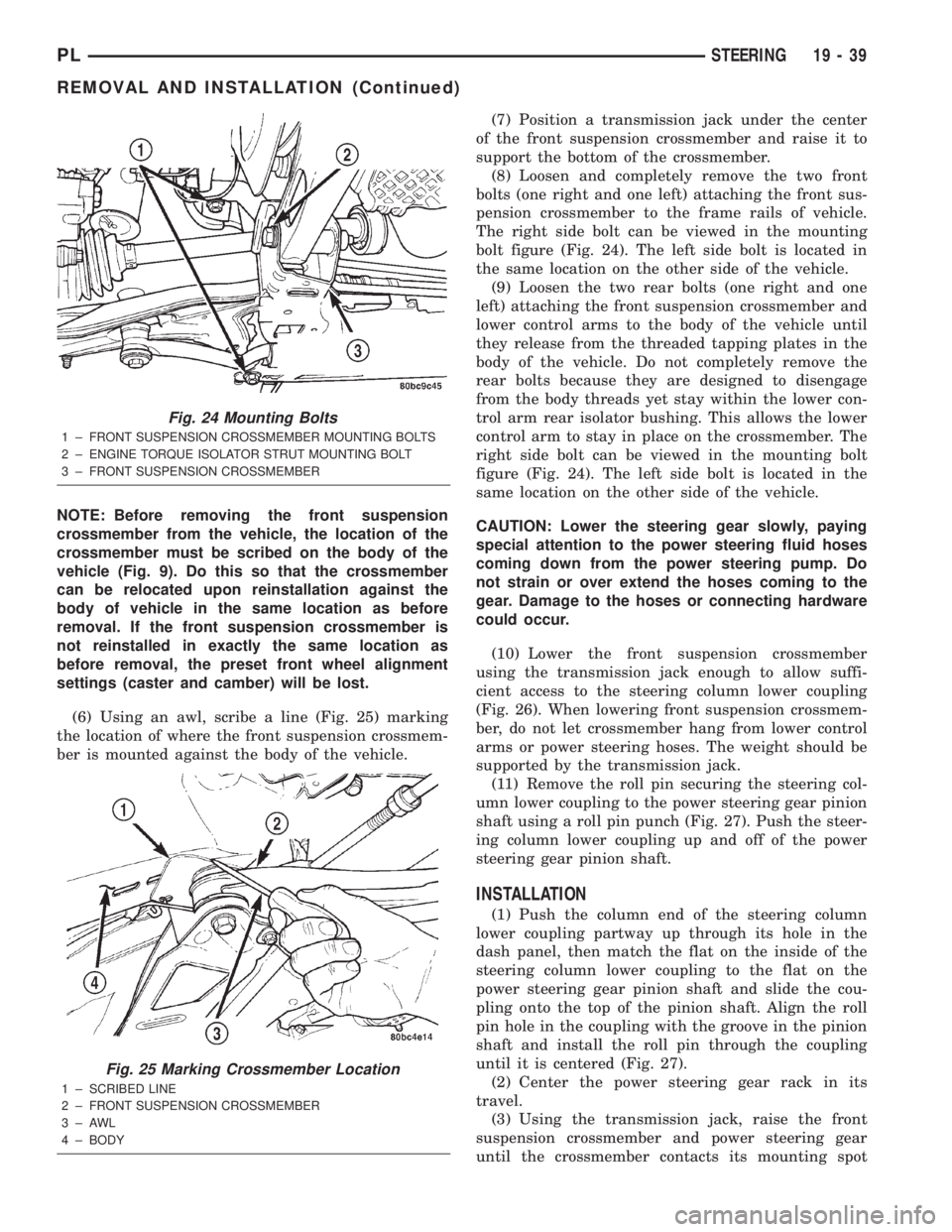
NOTE: Before removing the front suspension
crossmember from the vehicle, the location of the
crossmember must be scribed on the body of the
vehicle (Fig. 9). Do this so that the crossmember
can be relocated upon reinstallation against the
body of vehicle in the same location as before
removal. If the front suspension crossmember is
not reinstalled in exactly the same location as
before removal, the preset front wheel alignment
settings (caster and camber) will be lost.
(6) Using an awl, scribe a line (Fig. 25) marking
the location of where the front suspension crossmem-
ber is mounted against the body of the vehicle.(7) Position a transmission jack under the center
of the front suspension crossmember and raise it to
support the bottom of the crossmember.
(8) Loosen and completely remove the two front
bolts (one right and one left) attaching the front sus-
pension crossmember to the frame rails of vehicle.
The right side bolt can be viewed in the mounting
bolt figure (Fig. 24). The left side bolt is located in
the same location on the other side of the vehicle.
(9) Loosen the two rear bolts (one right and one
left) attaching the front suspension crossmember and
lower control arms to the body of the vehicle until
they release from the threaded tapping plates in the
body of the vehicle. Do not completely remove the
rear bolts because they are designed to disengage
from the body threads yet stay within the lower con-
trol arm rear isolator bushing. This allows the lower
control arm to stay in place on the crossmember. The
right side bolt can be viewed in the mounting bolt
figure (Fig. 24). The left side bolt is located in the
same location on the other side of the vehicle.
CAUTION: Lower the steering gear slowly, paying
special attention to the power steering fluid hoses
coming down from the power steering pump. Do
not strain or over extend the hoses coming to the
gear. Damage to the hoses or connecting hardware
could occur.
(10) Lower the front suspension crossmember
using the transmission jack enough to allow suffi-
cient access to the steering column lower coupling
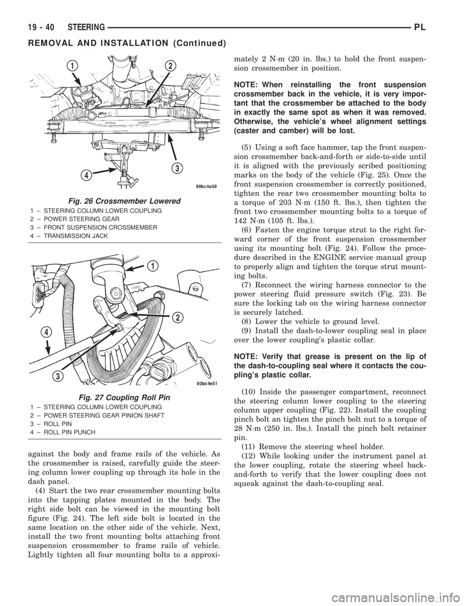
(Fig. 26). When lowering front suspension crossmem-
ber, do not let crossmember hang from lower control
arms or power steering hoses. The weight should be
supported by the transmission jack.
(11) Remove the roll pin securing the steering col-
umn lower coupling to the power steering gear pinion
shaft using a roll pin punch (Fig. 27). Push the steer-
ing column lower coupling up and off of the power
steering gear pinion shaft.
INSTALLATION
(1) Push the column end of the steering column
lower coupling partway up through its hole in the
dash panel, then match the flat on the inside of the
steering column lower coupling to the flat on the
power steering gear pinion shaft and slide the cou-
pling onto the top of the pinion shaft. Align the roll
pin hole in the coupling with the groove in the pinion
shaft and install the roll pin through the coupling
until it is centered (Fig. 27).
(2) Center the power steering gear rack in its
travel.
(3) Using the transmission jack, raise the front
suspension crossmember and power steering gear
until the crossmember contacts its mounting spot
Fig. 24 Mounting Bolts
1 ± FRONT SUSPENSION CROSSMEMBER MOUNTING BOLTS
2 ± ENGINE TORQUE ISOLATOR STRUT MOUNTING BOLT
3 ± FRONT SUSPENSION CROSSMEMBER
Fig. 25 Marking Crossmember Location
1 ± SCRIBED LINE
2 ± FRONT SUSPENSION CROSSMEMBER
3±AWL
4 ± BODY
PLSTEERING 19 - 39
REMOVAL AND INSTALLATION (Continued)
Page 911 of 1285
against the body and frame rails of the vehicle. As
the crossmember is raised, carefully guide the steer-
ing column lower coupling up through its hole in the
dash panel.
(4) Start the two rear crossmember mounting bolts
into the tapping plates mounted in the body. The
right side bolt can be viewed in the mounting bolt
figure (Fig. 24). The left side bolt is located in the
same location on the other side of the vehicle. Next,
install the two front mounting bolts attaching front
suspension crossmember to frame rails of vehicle.
Lightly tighten all four mounting bolts to a approxi-mately 2 N´m (20 in. lbs.) to hold the front suspen-
sion crossmember in position.
NOTE: When reinstalling the front suspension
crossmember back in the vehicle, it is very impor-
tant that the crossmember be attached to the body
in exactly the same spot as when it was removed.
Otherwise, the vehicle's wheel alignment settings
(caster and camber) will be lost.
(5) Using a soft face hammer, tap the front suspen-
sion crossmember back-and-forth or side-to-side until
it is aligned with the previously scribed positioning
marks on the body of the vehicle (Fig. 25). Once the
front suspension crossmember is correctly positioned,
tighten the rear two crossmember mounting bolts to
a torque of 203 N´m (150 ft. lbs.), then tighten the
front two crossmember mounting bolts to a torque of
142 N´m (105 ft. lbs.).
(6) Fasten the engine torque strut to the right for-
ward corner of the front suspension crossmember
using its mounting bolt (Fig. 24). Follow the proce-
dure described in the ENGINE service manual group
to properly align and tighten the torque strut mount-
ing bolts.
(7) Reconnect the wiring harness connector to the
power steering fluid pressure switch (Fig. 23). Be
sure the locking tab on the wiring harness connector
is securely latched.
(8) Lower the vehicle to ground level.
(9) Install the dash-to-lower coupling seal in place
over the lower coupling's plastic collar.
NOTE: Verify that grease is present on the lip of
the dash-to-coupling seal where it contacts the cou-
pling's plastic collar.
(10) Inside the passenger compartment, reconnect
the steering column lower coupling to the steering
column upper coupling (Fig. 22). Install the coupling
pinch bolt an tighten the pinch bolt nut to a torque of
28 N´m (250 in. lbs.). Install the pinch bolt retainer
pin.
(11) Remove the steering wheel holder.
(12) While looking under the instrument panel at
the lower coupling, rotate the steering wheel back-
and-forth to verify that the lower coupling does not
squeak against the dash-to-coupling seal.
Fig. 26 Crossmember Lowered
1 ± STEERING COLUMN LOWER COUPLING
2 ± POWER STEERING GEAR
3 ± FRONT SUSPENSION CROSSMEMBER
4 ± TRANSMISSION JACK
Fig. 27 Coupling Roll Pin
1 ± STEERING COLUMN LOWER COUPLING
2 ± POWER STEERING GEAR PINION SHAFT
3 ± ROLL PIN
4 ± ROLL PIN PUNCH
19 - 40 STEERINGPL
REMOVAL AND INSTALLATION (Continued)