wipers DODGE NEON 2000 Service Repair Manual
[x] Cancel search | Manufacturer: DODGE, Model Year: 2000, Model line: NEON, Model: DODGE NEON 2000Pages: 1285, PDF Size: 29.42 MB
Page 1 of 1285
GROUP TAB LOCATORINIntroductionINaIntroduction0Lubrication and Maintenance2Suspension3Differential and Driveline5Brakes6Clutch7Cooling8ABattery8BStarting8CCharging System8DIgnition System8EInstrument Panel and Systems8EaInstrument Panel and Systems8FAudio System8GHorns8HVehicle Speed Control System8JTurn Signal and Flashers8KWindshield Wipers and Washers8LLamps8LaLamps8MRestraint System8NElectrically Heated Systems8OPower Distribution Systems8PPower Door Locks8QImmobilizer System8SPower Windows8TPower Mirrors8TaPower Mirrors8UChime Warning/Reminder System8WWiring Diagrams - LHD and RHD9Engine11Exhaust System13Frame and Bumpers14Fuel System19Steering21Transaxle22Tires and Wheels23Body24Heating and Air Conditioning24aHeating and Air Conditioning25Emission Control Systems
Page 283 of 1285
REMOVAL AND INSTALLATION
HORN
REMOVAL
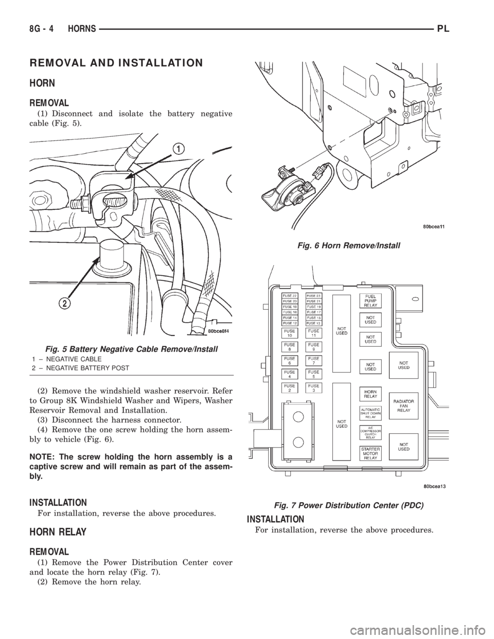
(1) Disconnect and isolate the battery negative
cable (Fig. 5).
(2) Remove the windshield washer reservoir. Refer
to Group 8K Windshield Washer and Wipers, Washer
Reservoir Removal and Installation.
(3) Disconnect the harness connector.
(4) Remove the one screw holding the horn assem-
bly to vehicle (Fig. 6).
NOTE: The screw holding the horn assembly is a
captive screw and will remain as part of the assem-
bly.
INSTALLATION
For installation, reverse the above procedures.
HORN RELAY
REMOVAL
(1) Remove the Power Distribution Center cover
and locate the horn relay (Fig. 7).
(2) Remove the horn relay.
INSTALLATION
For installation, reverse the above procedures.
Fig. 5 Battery Negative Cable Remove/Install
1 ± NEGATIVE CABLE
2 ± NEGATIVE BATTERY POST
Fig. 6 Horn Remove/Install
Fig. 7 Power Distribution Center (PDC)
8G - 4 HORNSPL
Page 298 of 1285
WINDSHIELD WIPER and WASHER SYSTEMS
TABLE OF CONTENTS
page page
WINDSHIELD WIPER SYSTEM................ 1WINDSHIELD WASHER SYSTEM.............. 8
WINDSHIELD WIPER SYSTEM
TABLE OF CONTENTS
page page
GENERAL INFORMATION
INTRODUCTION..........................1
DESCRIPTION AND OPERATION
WIPER BLADES...........................1
DIAGNOSIS AND TESTING
WINDSHIELD WIPER CONDITIONS............2
WINDSHIELD WIPER MOTOR................3
WINDSHIELD WIPER/WASHER SWITCH........5
REMOVAL AND INSTALLATION
WINDSHIELD WIPER ARM(S)................5WINDSHIELD WIPER BLADE(S)..............5
WINDSHIELD WIPER BLADE ELEMENT........5
WINDSHIELD WIPER LINKAGE...............5
WINDSHIELD WIPER MODULE...............6
WINDSHIELD WIPER MOTOR................6
WINDSHIELD WIPER/WASHER SWITCH........6
CLEANING AND INSPECTION
WINDSHIELD WIPER BLADE(S)..............6
ADJUSTMENTS
WINDSHIELD WIPER ARM(S)................6
GENERAL INFORMATION
INTRODUCTION
WARNING: ON VEHICLES EQUIPPED WITH AIR-
BAGS, REFER TO GROUP 8M, PASSIVE
RESTRAINT SYSTEMS FOR STEERING WHEEL
REMOVAL AND INSTALLATION.
The windshield wipers will only operate with the
ignition switch in the ACCESSORY or IGNITION
RUN position. The wiper circuit is protected against
over loads by a fuse in the fuse block and a circuit
breaker within the wiper motor. This protects the cir-
cuitry of the wiper system and the vehicle. The wiper
motor has permanent magnet fields.
The intermittent wiper system, in addition to low
and high speed, has a delay mode and a pulse wipe
mode. The delay mode has a range of 1 to 15 seconds.
Pulse wipe is accomplished by momentarily moving
the stalk lever into the WASH position while the
wiper switch is in either OFF or DELAY position.
The wiper blades then sweep once or twice and
return to the previous wiper switch mode, OFF or
DELAY.The intermittent wiper function is integral to the
wiper switch. All electronics and relay are inside the
switch assembly.
The wiper system completes the wipe cycle when
the switch is turned OFF. The blades park in the
lowest portion of the wipe pattern.
The wiper switch also includes the MIST feature
which provides a single wipe when actuated.
DESCRIPTION AND OPERATION
WIPER BLADES
Wiper blades, exposed to the weather for a long
period of time, tend to lose their wiping effectiveness.
Periodic cleaning of the wiper blade is suggested to
remove the accumulation of salt and road film. The
wiper blades, arms, and windshield should be
cleaned with a sponge or cloth and a mild detergent
or nonabrasive cleaner. If the blades continue to
streak or smear, they should be replaced. The right
and left wipers are different blade lengths. The
driver side length is 550 mm and the passenger side
length is 475 mm. The blades should not be inter-
changed.
PLWINDSHIELD WIPER and WASHER SYSTEMS 8K - 1
Page 300 of 1285
(a) If no voltage, repair wiring as necessary. If
OK, go to Step b.
(b) Check wiper switch low speed. Connect volt-
meter positive lead to terminal 6 of the wiper
switch connector. Move wiper stalk to LOW posi-
tion. If no voltage, replace switch.
(c) Check wiper switch high speed, connect volt-
meter positive lead to terminal 5 of the wiper
switch connector. Move wiper stalk to HIGH posi-
tion. If no voltage, replace switch.
(7) Disconnect motor connector and replace fuse 1
in fuse block.
(a) If fuse does not blow, replace motor.
(b) If fuse blows, disconnect wiper switch and
replace fuse.
(c) If fuse does not blow, replace switch.
(d) If fuse blows, repair wiring as necessary.
MOTOR OPERATES SLOWLY AT ALL SPEEDS
(1) Remove wiper arms and cowl screen. Discon-
nect motor linkage from motor. Connect an ammeter
between battery positive terminal and terminal 4 of
the motor connector. Turn wiper motor on and check
ampere reading.
If motor runs and ammeter reading is more than 6
amps, go to Step 2. If less than 6 amps, go to Step 3.
When replacing drive link nut tighten to 11 to 12
N´m (98 to 106 in. lbs.) torque.
(2) Using an ohmmeter, check the high and low
circuits for a short to ground. Refer to Group 8W,
Wiring Diagrams.
(3) Check to see if wiper linkage or pivots are
binding or caught.
WIPERS RUN AT HIGH SPEED WITH SWITCH IN
LOW SPEED POSITION OR WIPERS RUN AT LOW
SPEED WITH SWITCH IN HIGH SPEED POSITION.
(1) Check for crossed wires in the motor pigtail
wire connector. Refer to Group 8W, Wiring Diagrams.
(2) Check for crossed wires in harness connector
from wiper switch to motor.
(3) If OK, replace wiper switch.
WIPERS WILL OPERATE CONTINUOUSLY WITH
THE SWITCH IN THE INTERMITTENT POSITION -
WHEN WIPER SWITCH IS TURNED OFF, WIPERS
STOP WHEREVER THEY ARE WITHOUT
RETURNING TO PARK POSITION.
(1) Check at motor ground strap for a good ground.
(2) Turn ignition switch OFF. Disconnect the wiper
switch harness connector. Using an ohmmeter with
the motor in the park position, check for continuity
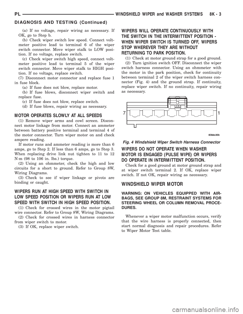
between terminal 2 of the wiper switch harness con-
nector (Fig. 4) and the ground strap. If continuity,
replace wiper switch. If no continuity, repair wiring
as necessary.
WIPERS DO NOT OPERATE WHEN WASHER
MOTOR IS ENGAGED (PULSE WIPE) OR WIPERS
DO OPERATE IN INTERMITTENT POSITION.
Check for a good ground at motor ground strap and
at wiper switch terminal 2. If OK, replace wiper
switch. If not OK, repair wiring as necessary.
WINDSHIELD WIPER MOTOR
WARNING: ON VEHICLES EQUIPPED WITH AIR-
BAGS, SEE GROUP 8M, RESTRAINT SYSTEMS FOR
STEERING WHEEL OR COLUMN REMOVAL PROCE-
DURES.
Whenever a wiper motor malfunction occurs, verify
that the wire harness is properly connected, then
start normal diagnosis and repair procedures. Refer
to Wiper Motor Test table.
Fig. 4 Windshield Wiper Switch Harness Connector
PLWINDSHIELD WIPER and WASHER SYSTEMS 8K - 3
DIAGNOSIS AND TESTING (Continued)
Page 303 of 1285
WINDSHIELD WIPER MODULE
REMOVAL
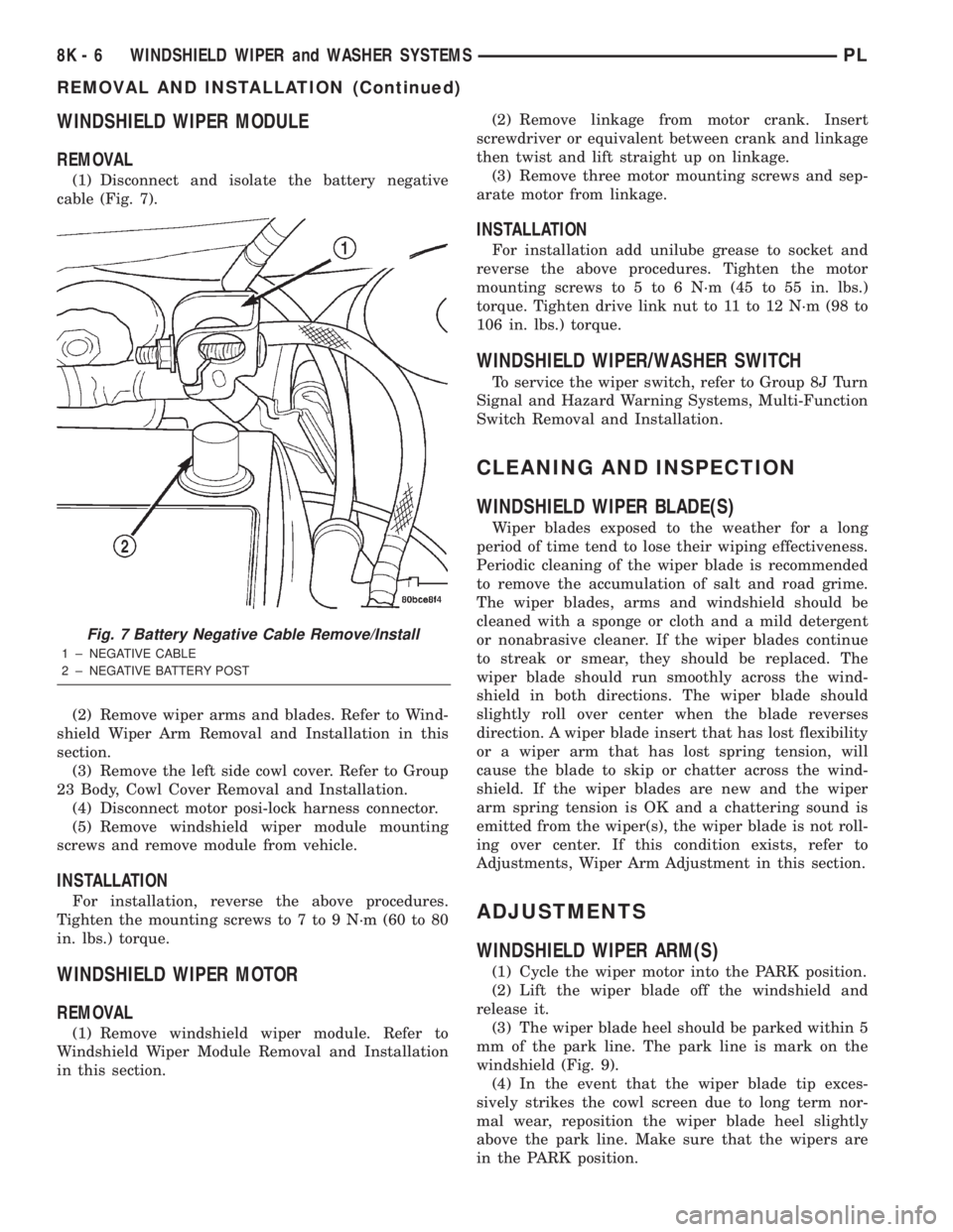
(1) Disconnect and isolate the battery negative
cable (Fig. 7).
(2) Remove wiper arms and blades. Refer to Wind-
shield Wiper Arm Removal and Installation in this
section.
(3) Remove the left side cowl cover. Refer to Group
23 Body, Cowl Cover Removal and Installation.
(4) Disconnect motor posi-lock harness connector.
(5) Remove windshield wiper module mounting
screws and remove module from vehicle.
INSTALLATION
For installation, reverse the above procedures.
Tighten the mounting screws to 7 to 9 N´m (60 to 80
in. lbs.) torque.
WINDSHIELD WIPER MOTOR
REMOVAL
(1) Remove windshield wiper module. Refer to
Windshield Wiper Module Removal and Installation
in this section.(2) Remove linkage from motor crank. Insert
screwdriver or equivalent between crank and linkage
then twist and lift straight up on linkage.
(3) Remove three motor mounting screws and sep-
arate motor from linkage.
INSTALLATION
For installation add unilube grease to socket and
reverse the above procedures. Tighten the motor
mounting screws to 5 to 6 N´m (45 to 55 in. lbs.)
torque. Tighten drive link nut to 11 to 12 N´m (98 to
106 in. lbs.) torque.
WINDSHIELD WIPER/WASHER SWITCH
To service the wiper switch, refer to Group 8J Turn
Signal and Hazard Warning Systems, Multi-Function
Switch Removal and Installation.
CLEANING AND INSPECTION
WINDSHIELD WIPER BLADE(S)
Wiper blades exposed to the weather for a long
period of time tend to lose their wiping effectiveness.
Periodic cleaning of the wiper blade is recommended
to remove the accumulation of salt and road grime.
The wiper blades, arms and windshield should be
cleaned with a sponge or cloth and a mild detergent
or nonabrasive cleaner. If the wiper blades continue
to streak or smear, they should be replaced. The
wiper blade should run smoothly across the wind-
shield in both directions. The wiper blade should
slightly roll over center when the blade reverses
direction. A wiper blade insert that has lost flexibility
or a wiper arm that has lost spring tension, will
cause the blade to skip or chatter across the wind-
shield. If the wiper blades are new and the wiper
arm spring tension is OK and a chattering sound is
emitted from the wiper(s), the wiper blade is not roll-
ing over center. If this condition exists, refer to
Adjustments, Wiper Arm Adjustment in this section.
ADJUSTMENTS
WINDSHIELD WIPER ARM(S)
(1) Cycle the wiper motor into the PARK position.
(2) Lift the wiper blade off the windshield and
release it.
(3) The wiper blade heel should be parked within 5
mm of the park line. The park line is mark on the
windshield (Fig. 9).
(4) In the event that the wiper blade tip exces-
sively strikes the cowl screen due to long term nor-
mal wear, reposition the wiper blade heel slightly
above the park line. Make sure that the wipers are
in the PARK position.
Fig. 7 Battery Negative Cable Remove/Install
1 ± NEGATIVE CABLE
2 ± NEGATIVE BATTERY POST
8K - 6 WINDSHIELD WIPER and WASHER SYSTEMSPL
REMOVAL AND INSTALLATION (Continued)
Page 305 of 1285
WINDSHIELD WASHER SYSTEM
TABLE OF CONTENTS
page page
DESCRIPTION AND OPERATION
WINDSHIELD WASHER NOZZLE(S)............8
WINDSHIELD WASHER SYSTEM.............8
DIAGNOSIS AND TESTING
WINDSHIELD WASHER SYSTEM.............9REMOVAL AND INSTALLATION
WINDSHIELD WASHER HOSE................9
WINDSHIELD WASHER NOZZLES.............9
WINDSHIELD WASHER RESERVOIR..........10
WINDSHIELD WASHER PUMP...............10
DESCRIPTION AND OPERATION
WINDSHIELD WASHER NOZZLE(S)
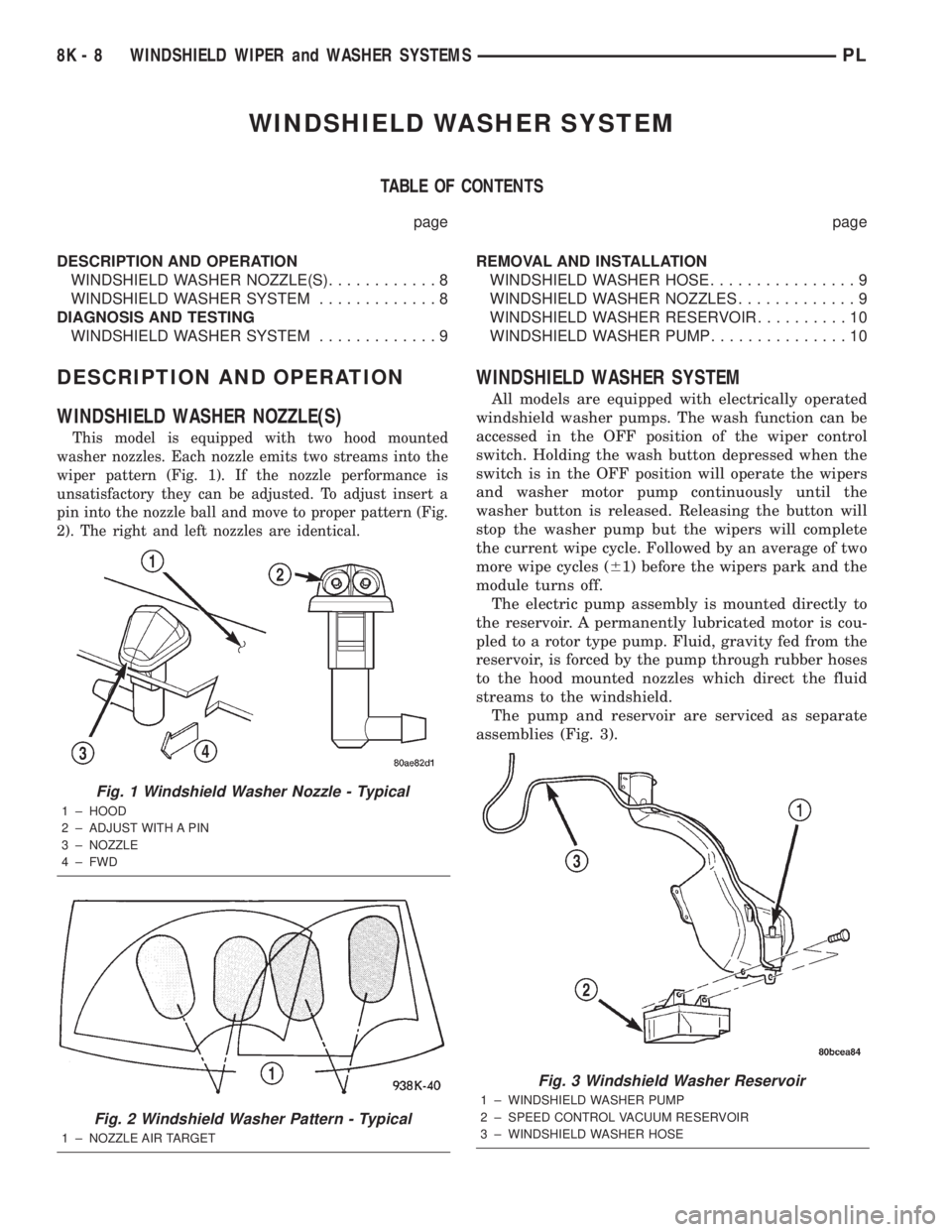
This model is equipped with two hood mounted
washer nozzles. Each nozzle emits two streams into the
wiper pattern (Fig. 1). If the nozzle performance is
unsatisfactory they can be adjusted. To adjust insert a
pin into the nozzle ball and move to proper pattern (Fig.
2). The right and left nozzles are identical.
WINDSHIELD WASHER SYSTEM
All models are equipped with electrically operated
windshield washer pumps. The wash function can be
accessed in the OFF position of the wiper control
switch. Holding the wash button depressed when the
switch is in the OFF position will operate the wipers
and washer motor pump continuously until the
washer button is released. Releasing the button will
stop the washer pump but the wipers will complete
the current wipe cycle. Followed by an average of two
more wipe cycles (61) before the wipers park and the
module turns off.
The electric pump assembly is mounted directly to
the reservoir. A permanently lubricated motor is cou-
pled to a rotor type pump. Fluid, gravity fed from the
reservoir, is forced by the pump through rubber hoses
to the hood mounted nozzles which direct the fluid
streams to the windshield.
The pump and reservoir are serviced as separate
assemblies (Fig. 3).
Fig. 1 Windshield Washer Nozzle - Typical
1 ± HOOD
2 ± ADJUST WITH A PIN
3 ± NOZZLE
4 ± FWD
Fig. 2 Windshield Washer Pattern - Typical
1 ± NOZZLE AIR TARGET
Fig. 3 Windshield Washer Reservoir
1 ± WINDSHIELD WASHER PUMP
2 ± SPEED CONTROL VACUUM RESERVOIR
3 ± WINDSHIELD WASHER HOSE
8K - 8 WINDSHIELD WIPER and WASHER SYSTEMSPL
Page 392 of 1285
WIRING DIAGRAMS
TABLE OF CONTENTS
page page
AIR CONDITIONING-HEATER........... 8W-42-1
AIRBAG SYSTEM.................... 8W-43-1
ANTI-LOCK BRAKES.................. 8W-35-1
AUDIO SYSTEM..................... 8W-47-1
CHARGING SYSTEM.................. 8W-20-1
COMPONENT INDEX.................. 8W-02-1
CONNECTOR PIN-OUTS............... 8W-80-1
CONNECTOR/GROUND LOCATIONS...... 8W-90-1
FRONT LIGHTING.................... 8W-50-1
FUEL/IGNITION SYSTEM.............. 8W-30-1
FUSE BLOCK........................ 8W-11-1
GENERAL INFORMATION.............. 8W-01-1
GROUND DISTRIBUTION.............. 8W-15-1
HORN/CIGAR LIGHTER/POWER OUTLET . . 8W-41-1
INSTRUMENT CLUSTER............... 8W-40-1INTERIOR LIGHTING.................. 8W-44-1
POWER DISTRIBUTION............... 8W-10-1
POWER DOOR LOCKS................ 8W-61-1
POWER MIRRORS................... 8W-62-1
POWER SUNROOF................... 8W-64-1
POWER WINDOWS................... 8W-60-1
REAR LIGHTING..................... 8W-51-1
REAR WINDOW DEFOGGER............ 8W-48-1
SPLICE INFORMATION................ 8W-70-1
SPLICE LOCATIONS.................. 8W-95-1
STARTING SYSTEM.................. 8W-21-1
TURN SIGNALS...................... 8W-52-1
VEHICLE THEFT SECURITY SYSTEM..... 8W-39-1
WIPERS............................ 8W-53-1
PLWIRING DIAGRAMS 8W - 1
Page 398 of 1285
SECTION IDENTIFICATION
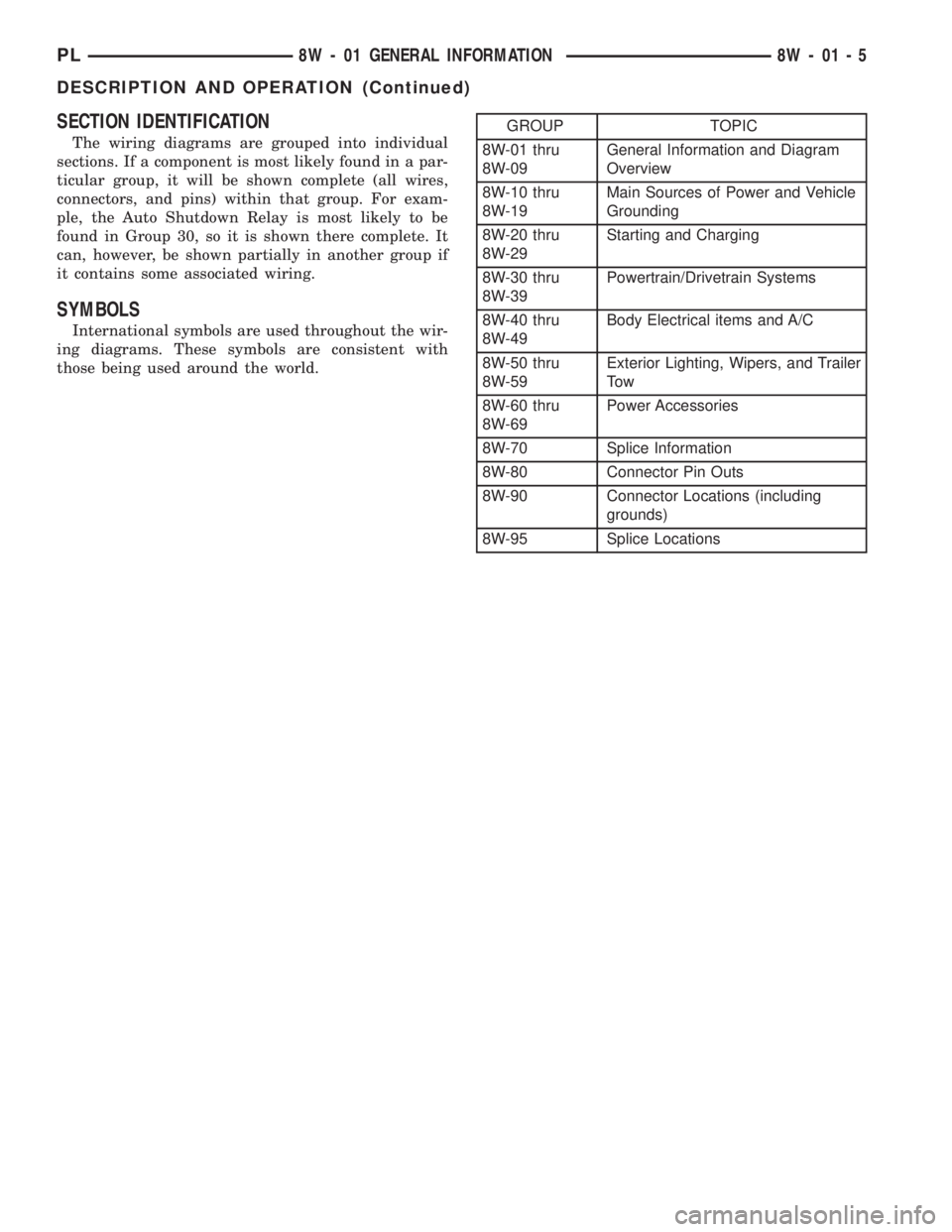
The wiring diagrams are grouped into individual
sections. If a component is most likely found in a par-
ticular group, it will be shown complete (all wires,
connectors, and pins) within that group. For exam-
ple, the Auto Shutdown Relay is most likely to be
found in Group 30, so it is shown there complete. It
can, however, be shown partially in another group if
it contains some associated wiring.
SYMBOLS
International symbols are used throughout the wir-
ing diagrams. These symbols are consistent with
those being used around the world.
GROUP TOPIC
8W-01 thru
8W-09General Information and Diagram
Overview
8W-10 thru
8W-19Main Sources of Power and Vehicle
Grounding
8W-20 thru
8W-29Starting and Charging
8W-30 thru
8W-39Powertrain/Drivetrain Systems
8W-40 thru
8W-49Body Electrical items and A/C
8W-50 thru
8W-59Exterior Lighting, Wipers, and Trailer
To w
8W-60 thru
8W-69Power Accessories
8W-70 Splice Information
8W-80 Connector Pin Outs
8W-90 Connector Locations (including
grounds)
8W-95 Splice Locations
PL8W - 01 GENERAL INFORMATION 8W - 01 - 5
DESCRIPTION AND OPERATION (Continued)
Page 580 of 1285
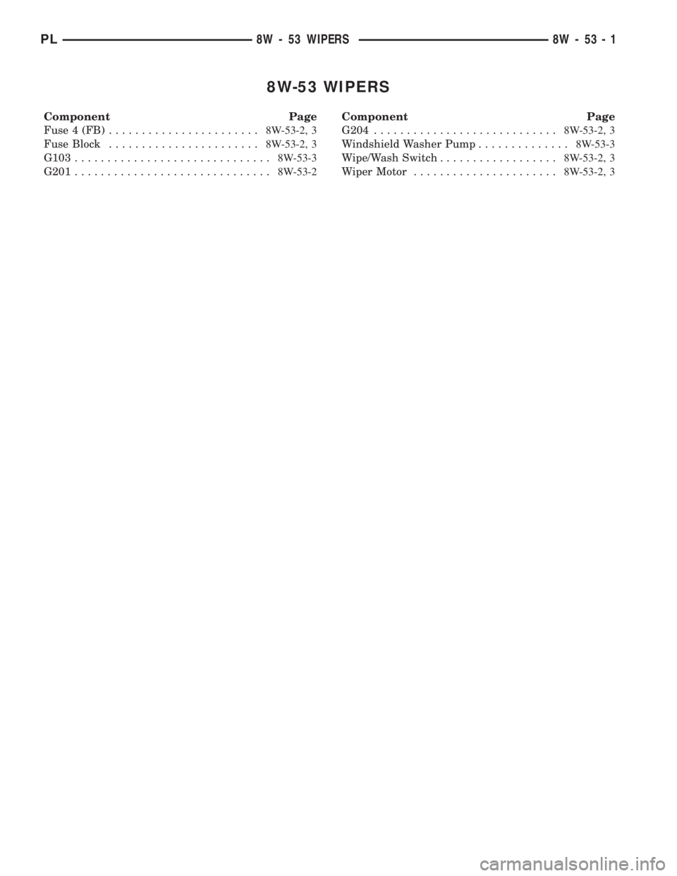
8W-53 WIPERS
Component Page
Fuse 4 (FB).......................8W-53-2, 3
Fuse Block.......................8W-53-2, 3
G103..............................8W-53-3
G201..............................8W-53-2Component Page
G204............................8W-53-2, 3
Windshield Washer Pump..............8W-53-3
Wipe/Wash Switch..................8W-53-2, 3
Wiper Motor......................8W-53-2, 3
PL8W - 53 WIPERS 8W - 53 - 1
Page 581 of 1285

FUSE
BLOCK
4FUSE10A
RUN-ACC A31
S202
C20251 3
2 4
4C202
G201G204
S207
Z2
22
BK/LG
Z2
20
BK/LGZ1
16
BK
Z1
16
BK
V6
16
DB
V6
16
DBV6
16
DB
FUSED
IGNITION
SWITCH
OUTPUT
(RUN-ACC)
GROUND 244
MOTOR WIPER
2
0
1 2 33
210
MITTENT
WIPER
CONTROL
1
INTER-
563
4
6
5
TIME
DELAYWASHER/
PULSE
WIPE
WIPER
RELAY6 MAXIMUM 5 MINIMUM
WIPE/
3 HIGH 2 LOW
1 DELAY
0 OFF
WASH
SWITCH
4 MIST
Z1
16
BK
(8W-11-2)
(8W-11-3)
(8W-11-6)(8W-10-10)
(8W-15-11)
(8W-15-8)(8W-15-11) (8W-15-8)(8W-53-3)
8W - 53 - 2 8W-53 WIPERSPL
008W-10PLI05302