DODGE POWER WAGON 2007 2.G Owners Manual
Manufacturer: DODGE, Model Year: 2007, Model line: POWER WAGON, Model: DODGE POWER WAGON 2007 2.GPages: 492, PDF Size: 8.25 MB
Page 171 of 492
NRadio Operation......................224
NTape Player.........................225
NCD Player..........................225
mCassette Tape And Player Maintenance.......225
mCompact Disc Maintenance................226
mRadio Operation And Cellular Phones........227
mClimate Controls.......................227NHeater Only Ð Fleet Vehicles.............228
NAir Conditioning And Heating Ð If Equipped . 230
NAir Conditioning With Dual Zone Temperature
Control Ð If Equipped.................233
NOperating Tips.......................237
NOperating Tips Chart...................240
170 UNDERSTANDING YOUR INSTRUMENT PANEL
Page 172 of 492
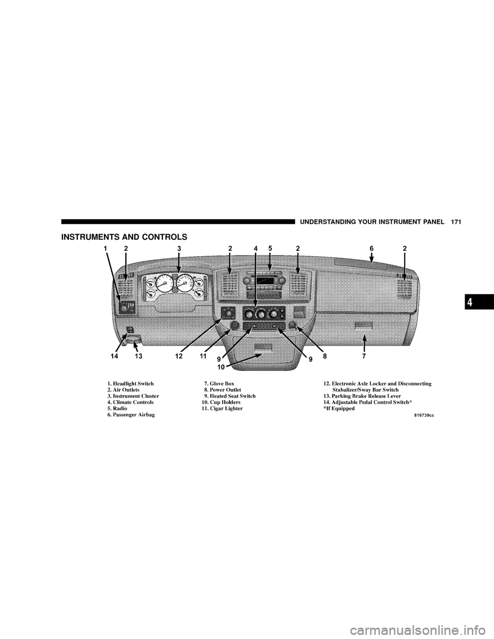
INSTRUMENTS AND CONTROLS
UNDERSTANDING YOUR INSTRUMENT PANEL 171
4
Page 173 of 492
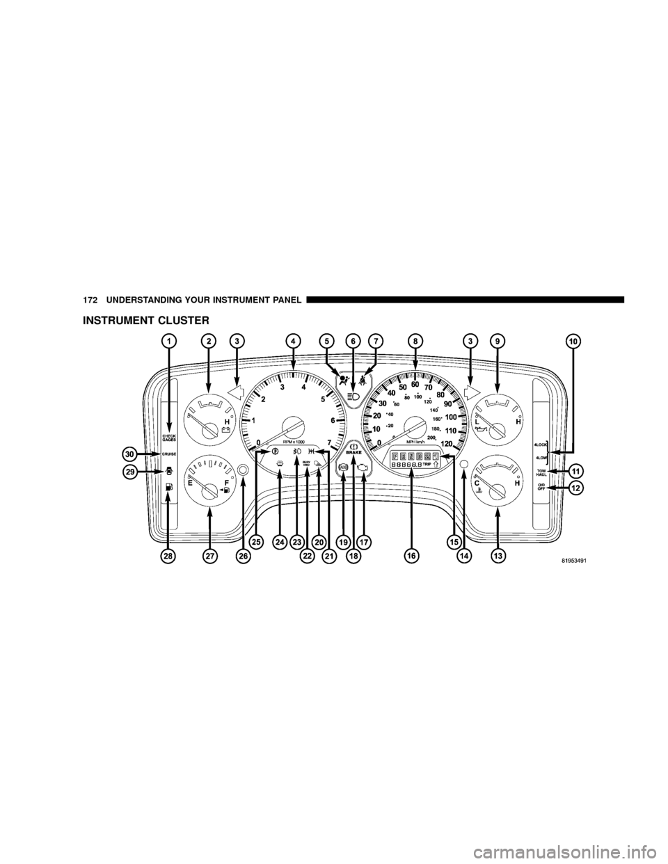
INSTRUMENT CLUSTER
172 UNDERSTANDING YOUR INSTRUMENT PANEL
Page 174 of 492
INSTRUMENT CLUSTER DESCRIPTION
1. Check Gages
This light illuminates when the Voltmeter, Engine
Oil Pressure or Engine Coolant Temperature
gages indicate a reading either too high or too low.
Examine the gages carefully, and follow the instructions
above for each indicated problem.
NOTE:When the ignition switch is turned to OFF, the
Fuel Gage, Voltmeter, Oil Pressure and Engine Coolant
Temperature gages may not show accurate readings.
When the engine is not running, turn the ignition switch
to ON to obtain accurate readings.
2. Voltage Gauge
When the engine is running, the gauge indicates
the electrical system voltage. The pointer should
stay within the normal range if the battery is charged. Ifthe pointer moves to either extreme left or right and
remains there during normal driving, the electrical sys-
tem should be serviced.
NOTE:If the gauge pointer moves to either extreme of
the gauge, the ªCheck Gagesº indicator will illuminate
and a single chime will sound. The ªCheck Gagesº
indicator may also illuminate prior to the voltage gauge
moving out of normal range. In either case, see you local
authorized Dealer for system service.
3. Turn Signal Indicators
Lights in instrument cluster flash when outside turn
signals are operating.
4. Tachometer
The tachometer indicates engine speed in revolutions per
minute.
UNDERSTANDING YOUR INSTRUMENT PANEL 173
4
Page 175 of 492
CAUTION!
Do not operate the engine with the tachometer
pointer at high rpm for extended periods. Engine
damage may occur.
5. Airbag Indicator Light
The indicator lights and remains lit for 6 to 8 seconds
when the ignition is first turned on. If the light stays on,
flickers or comes on while driving, have the airbag
system checked by an authorized dealer.
6. High Beam Indicator
This indicator shows that headlights are on high
beam.
7. Seat Belt Reminder Light
When the ignition switch is first turned ON, this
light will turn on for 5 to 8 seconds as a bulb check.
During the bulb check, if the driver's seat belt isunbuckled, a chime will sound. After the bulb check or
when driving, if the driver seat belt remains unbuckled,
the Seat Belt Warning Light will flash or remain on
continuously. Refer to9Enhanced Driver Seat Belt Re-
minder System (BeltAlertŸ)9in the Occupant Restraints
section for more information. (See page 43 for more
information.)
8. Speedometer
The speedometer shows the vehicle speed in miles per
hour and/or kilometers per hour.
9. Oil Pressure Gauge
The pointer should always indicate some oil pres-
sure when the engine is running. A continuous
high or low reading, under normal driving conditions,
may indicate a lubrication system malfunction. Immedi-
ate service should be obtained. (See page 389 for more
information.)
174 UNDERSTANDING YOUR INSTRUMENT PANEL
Page 176 of 492
NOTE:If the gauge pointer moves to either extreme of
the gauge, the ªCheck Gagesº indicator will illuminate
and a single chime will sound.
10. Transfer Case Position
(See page 258 for more information.)
11 .TOW HAUL
The TOW HAUL button is located at the end of the gear
shift lever. This light will illuminate when the TOW
HAUL OD/OFF button is pushed once. (See page 254 for
more information.)
12.OD/OFF
the OD/OFF button is located at the end of the gear shift
lever. This light will illuminate when the TOW HAUL
OD/OFF button is pushed twice. (See page 254 for more
information.)13. Temperature Gauge
The temperature gauge indicates engine coolant
temperature. Any reading within the normal
range indicates that the cooling system is operat-
ing satisfactorily. The gauge needle will likely indicate a
higher temperature when driving in hot weather, up
mountain grades, in heavy traffic, or when towing a
trailer. If the needle rises to the ª245ÉFº mark, stop the
vehicle, shift into N (Neutral), and increase the engine
idle speed for 2 to 3 minutes. If the temperature reading
does not return to normal, shut your engine OFF and
allow it to cool. Seek authorized service immediately. See
Cooling System information in the section on ªMaintain-
ing Your Vehicle.º
UNDERSTANDING YOUR INSTRUMENT PANEL 175
4
Page 177 of 492
CAUTION!
Do not leave your vehicle unattended with the
engine running as you would not be able to react to
the temperature indicator if the engine overheats.
NOTE:Engine idle speed will automatically increase to
1000 rpm at elevated coolant temperatures to improve
engine cooling.
NOTE:If the gauge pointer moves to either extreme of
the gauge, the ªCheck Gagesº indicator will illuminate
and a single chime will sound.
14. Security
The light will flash rapidly for approximately 16 seconds
when the vehicle theft alarm is arming. The light will
flash at a slower rate after the alarm is set. The security
light will also come on for about two seconds when the
ignition is first turned ON.15. Transmission Range Indicator (Automatic
Tranmissions Only)
When the gear selector lever is moved, this indicator
shows the automatic transmission gear range selected.
16. Odometer/Trip Odometer
The odometer shows the total distance the vehicle has
been driven.
If the odometer reading is changed during repair or
replacement, be sure to keep a record of the reading
before and after the service so that the correct mileage can
be determined.
The trip odometer shows individual trip mileage. To
toggle between the odometer and the trip odometer,
press the Odometer/Trip Odometer Button. To reset the
Trip Odometer, press and hold the button while in trip
mode, until the Trip Odometer resets.
176 UNDERSTANDING YOUR INSTRUMENT PANEL
Page 178 of 492
NOTE:The odometer/trip odometer Vacuum Fluores-
cent Display will also may display GASCAP, which
indicates that your gas cap is possibly loose or damaged.
The Vacuum Fluorescent Display will also display NO-
FUSE, which indicates that the IOD fuse is removed from
the Integrated Power Module. (See page 430 for more
information.)
NOTE:There is also an engine hour function. This
indicates the total number of hours the engine has been
running. To display the engine hours perform the follow-
ing: Place the ignition in RUN, but do not start the
engine. With the odometer value displayed, hold the trip
button down for a period of 6 seconds. The odometer will
change to trip value first, then it will display the engine
hour value. The engine hours will be displayed for a
period of 30 seconds until the ignition is turned off or the
engine is started.17. Check Gages Light
This light is part of an onboard diagnostic system
which monitors the emissions and engine control
system. If the vehicle is ready for emissions
testing the light will come on when the ignition is first
turned on and remain on, as a bulb check, until the
engine is started. If the vehicle is not ready for emissions
testing the light will come on when the ignition is first
turned on and remain on for 15 seconds, then blink for 5
seconds, and remain on until the vehicle is started. If the
bulb does not come on during starting, have the condi-
tion investigated promptly.
If this light comes on and remains on while driving, it
suggests a potential engine control problem and the need
for system service.
Although your vehicle will usually be drivable and not
need towing, see your dealer for service as soon as
possible.
UNDERSTANDING YOUR INSTRUMENT PANEL 177
4
Page 179 of 492
CAUTION!
Prolonged driving with the MIL on could cause
damage to the engine control system. It also could
affect fuel economy and driveability.
If the MIL is flashing, severe catalytic converter
damage and power loss will soon occur. Immediate
service is required.
18. Brake System Warning Light
This light illuminates when the ignition key is turned to
the ON position and remains on for a few seconds. If the
light stays on longer, it may be an indication that the
parking brake has not been released. This light will
illuminate if the brake fluid is low, especially when
braking or accelerating hard. This light will illuminate if
the ABS indicator light has a malfunction. This light will
flash if the engine is running and the parking brake is on.If the light remains on when the parking brake is
released, it indicates a possible brake hydraulic system
malfunction. In this case, the light will remain on until
the cause is corrected.
If brake failure is indicated, immediate repair is necessary
and continued operation of the vehicle in this condition is
dangerous.
Acceleration which causes the rear wheels to slip for a
period of time may result in the red brake light illumi-
nating and a brake switch code being set on ABS
equipped vehicles. Depressing the brake pedal should
extinguish the red brake light.
19. ABS Warning Light
This light monitors the Anti-Lock Brake System
which is described elsewhere in this manual. This
light will come on when the ignition key is turned to the
ON position and may stay on for five seconds. If the ABS
light remains on or comes on during driving, it indicates
178 UNDERSTANDING YOUR INSTRUMENT PANEL
Page 180 of 492
that the anti-lock portion of the brake system is not
functioning and that service is required. See your autho-
rized dealer immediately. The ABS light could also
illuminate during loss of traction and remain illuminated
until the brake pedal is pressed.
20. Cargo Light
The Cargo Lamp light will illuminate when the Cargo
Lamp is activated by pressing the Cargo Light Button on
the headlight switch.
21. Electronic Throttle Control (ETC)
This light informs you of a problem with the
Electronic Throttle Control system. If a prob-
lem is detected the light will come on while the
engine is running. If the light remains lit with
the engine running your vehicle will usually be drivable,
however, see your dealer for service as soon as possible.
If the light is flashing when the engine is running,
immediate service is required and you may experiencereduced performance, an elevated/rough idle or engine
stall and your vehicle may require towing. The light will
come on when the ignition is first turned on and remain
on for 15 seconds as a bulb check. If the light does not
come on during starting, have the system checked by an
authorized dealer.
22. SERV 4WD Indicator
The 4WD indicator will be illuminated whenever the
4WD mode is engaged for either the manual or electric
shift 4WD systems. The SERV 4WD indicator monitors
the electric shift 4WD system. If the SERV 4WD light
stays on or comes on during driving, it means that the
4WD system is not functioning properly and that service
is required.
23. Front Fog Light Indicator Ð If Equipped
This light shows when the front fog lights are ON.
UNDERSTANDING YOUR INSTRUMENT PANEL 179
4