Fig DODGE RAM 1500 1998 2.G Workshop Manual
[x] Cancel search | Manufacturer: DODGE, Model Year: 1998, Model line: RAM 1500, Model: DODGE RAM 1500 1998 2.GPages: 2627
Page 1748 of 2627
(5) Remove shift tower and isolator plate from
transmission shift cover.
(6) Raise and support vehicle.
(7) Remove skid plate, if equipped.
(8) Mark propeller shaft and axle yokes for instal-
lation reference and remove shaft/shafts.
(9) Remove exhaust system Y-pipe.
(10) Disconnect speed sensor and backup light
switch connectors.
(11) Support engine with safety stand and a wood
block.
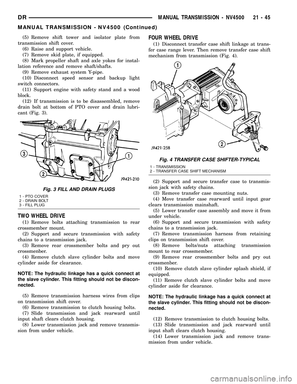
(12) If transmission is to be disassembled, remove
drain bolt at bottom of PTO cover and drain lubri-
cant (Fig. 3).
TWO WHEEL DRIVE
(1) Remove bolts attaching transmission to rear
crossmember mount.
(2) Support and secure transmission with safety
chains to a transmission jack.
(3) Remove rear crossmember bolts and pry out
crossmenber.
(4) Remove clutch slave cylinder bolts and move
cylinder aside for clearance.
NOTE: The hydraulic linkage has a quick connect at
the slave cylinder. This fitting should not be discon-
nected.
(5) Remove transmission harness wires from clips
on transmission shift cover.
(6) Remove transmission to clutch housing bolts.
(7) Slide transmission and jack rearward until
input shaft clears clutch housing.
(8) Lower transmission jack and remove transmis-
sion from under vehicle.
FOUR WHEEL DRIVE
(1) Disconnect transfer case shift linkage at trans-
fer case range lever. Then remove transfer case shift
mechanism from transmission (Fig. 4).
(2) Support and secure transfer case to transmis-
sion jack with safety chains.
(3) Remove transfer case mounting nuts.
(4) Move transfer case rearward until input gear
clears transmission mainshaft.
(5) Lower transfer case assembly and move it from
under vehicle.
(6) Support and secure transmission with safety
chains to a transmission jack.
(7) Remove transmission harness from retaining
clips on transmission shift cover.
(8) Remove bolts/nuts attaching transmission
mount to rear crossmember.
(9) Remove rear crossmember bolts and pry out
crossmenber.
(10) Remove clutch slave cylinder splash shield, if
equipped.
(11) Remove clutch slave cylinder bolts and move
cylinder aside for clearance.
NOTE: The hydraulic linkage has a quick connect at
the slave cylinder. This fitting should not be discon-
nected.
(12) Remove transmission to clutch housing bolts.
(13) Slide transmission and jack rearward until
input shaft clears clutch housing.
(14) Lower transmission jack and remove trans-
mission from under vehicle.
Fig. 3 FILL AND DRAIN PLUGS
1 - PTO COVER
2 - DRAIN BOLT
3 - FILL PLUG
Fig. 4 TRANSFER CASE SHIFTER-TYPICAL
1 - TRANSMISSION
2 - TRANSFER CASE SHIFT MECHANISM
DRMANUAL TRANSMISSION - NV4500 21 - 45
MANUAL TRANSMISSION - NV4500 (Continued)
Page 1749 of 2627
DISASSEMBLY
SHIFT MECHANISM
(1) Remove bolts holding shift tower to shift mech-
anism cover and remove tower.
(2) Remove bolts holding shift mechanism cover to
transmission.
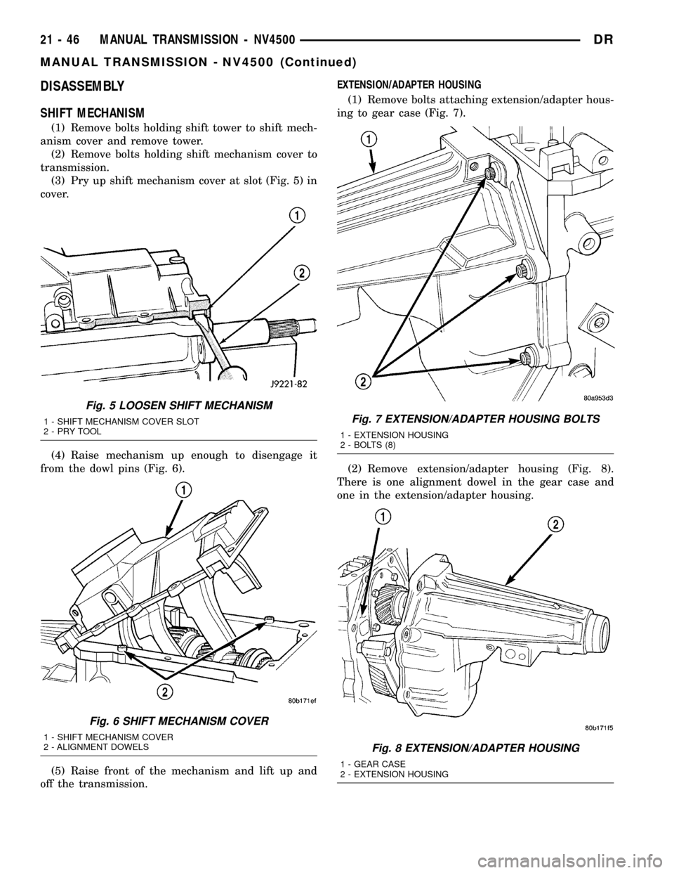
(3) Pry up shift mechanism cover at slot (Fig. 5) in
cover.
(4) Raise mechanism up enough to disengage it
from the dowl pins (Fig. 6).
(5) Raise front of the mechanism and lift up and
off the transmission.EXTENSION/ADAPTER HOUSING
(1) Remove bolts attaching extension/adapter hous-
ing to gear case (Fig. 7).
(2) Remove extension/adapter housing (Fig. 8).
There is one alignment dowel in the gear case and
one in the extension/adapter housing.
Fig. 5 LOOSEN SHIFT MECHANISM
1 - SHIFT MECHANISM COVER SLOT
2-PRYTOOL
Fig. 6 SHIFT MECHANISM COVER
1 - SHIFT MECHANISM COVER
2 - ALIGNMENT DOWELS
Fig. 7 EXTENSION/ADAPTER HOUSING BOLTS
1 - EXTENSION HOUSING
2 - BOLTS (8)
Fig. 8 EXTENSION/ADAPTER HOUSING
1 - GEAR CASE
2 - EXTENSION HOUSING
21 - 46 MANUAL TRANSMISSION - NV4500DR
MANUAL TRANSMISSION - NV4500 (Continued)
Page 1750 of 2627
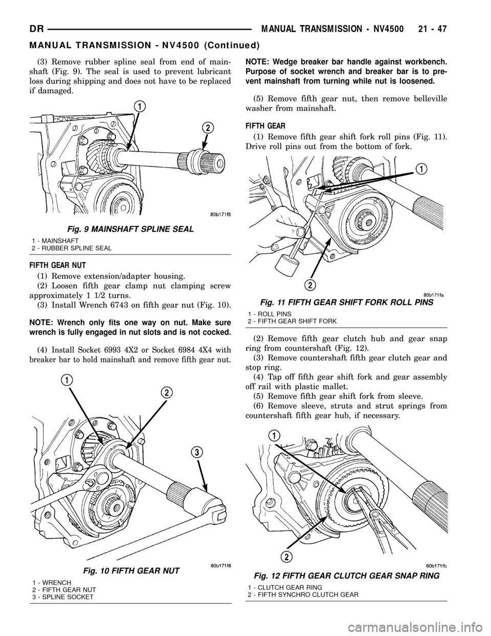
(3) Remove rubber spline seal from end of main-
shaft (Fig. 9). The seal is used to prevent lubricant
loss during shipping and does not have to be replaced
if damaged.
FIFTH GEAR NUT
(1) Remove extension/adapter housing.
(2) Loosen fifth gear clamp nut clamping screw
approximately 1 1/2 turns.
(3) Install Wrench 6743 on fifth gear nut (Fig. 10).
NOTE: Wrench only fits one way on nut. Make sure
wrench is fully engaged in nut slots and is not cocked.
(4)Install Socket 6993 4X2 or Socket 6984 4X4 with
breaker bar to hold mainshaft and remove fifth gear nut.
NOTE: Wedge breaker bar handle against workbench.
Purpose of socket wrench and breaker bar is to pre-
vent mainshaft from turning while nut is loosened.
(5) Remove fifth gear nut, then remove belleville
washer from mainshaft.
FIFTH GEAR
(1) Remove fifth gear shift fork roll pins (Fig. 11).
Drive roll pins out from the bottom of fork.
(2) Remove fifth gear clutch hub and gear snap
ring from countershaft (Fig. 12).
(3) Remove countershaft fifth gear clutch gear and
stop ring.
(4) Tap off fifth gear shift fork and gear assembly
off rail with plastic mallet.
(5) Remove fifth gear shift fork from sleeve.
(6) Remove sleeve, struts and strut springs from
countershaft fifth gear hub, if necessary.
Fig. 10 FIFTH GEAR NUT
1 - WRENCH
2 - FIFTH GEAR NUT
3 - SPLINE SOCKET
Fig. 9 MAINSHAFT SPLINE SEAL
1 - MAINSHAFT
2 - RUBBER SPLINE SEAL
Fig. 11 FIFTH GEAR SHIFT FORK ROLL PINS
1 - ROLL PINS
2 - FIFTH GEAR SHIFT FORK
Fig. 12 FIFTH GEAR CLUTCH GEAR SNAP RING
1 - CLUTCH GEAR RING
2 - FIFTH SYNCHRO CLUTCH GEAR
DRMANUAL TRANSMISSION - NV4500 21 - 47
MANUAL TRANSMISSION - NV4500 (Continued)
Page 1751 of 2627
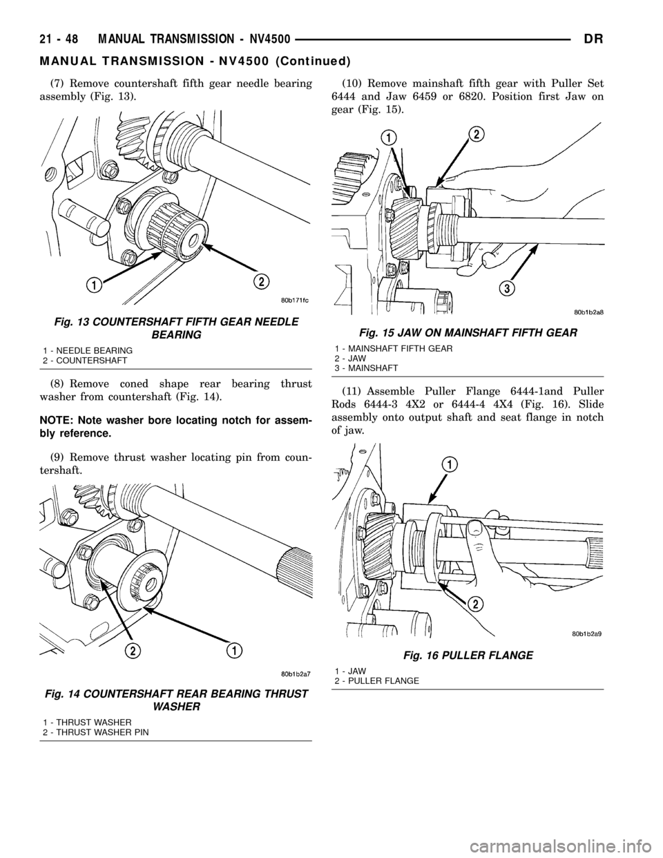
(7) Remove countershaft fifth gear needle bearing
assembly (Fig. 13).
(8) Remove coned shape rear bearing thrust
washer from countershaft (Fig. 14).
NOTE: Note washer bore locating notch for assem-
bly reference.
(9) Remove thrust washer locating pin from coun-
tershaft.(10) Remove mainshaft fifth gear with Puller Set
6444 and Jaw 6459 or 6820. Position first Jaw on
gear (Fig. 15).
(11) Assemble Puller Flange 6444-1and Puller
Rods 6444-3 4X2 or 6444-4 4X4 (Fig. 16). Slide
assembly onto output shaft and seat flange in notch
of jaw.
Fig. 13 COUNTERSHAFT FIFTH GEAR NEEDLE
BEARING
1 - NEEDLE BEARING
2 - COUNTERSHAFT
Fig. 14 COUNTERSHAFT REAR BEARING THRUST
WASHER
1 - THRUST WASHER
2 - THRUST WASHER PIN
Fig. 15 JAW ON MAINSHAFT FIFTH GEAR
1 - MAINSHAFT FIFTH GEAR
2-JAW
3 - MAINSHAFT
Fig. 16 PULLER FLANGE
1-JAW
2 - PULLER FLANGE
21 - 48 MANUAL TRANSMISSION - NV4500DR
MANUAL TRANSMISSION - NV4500 (Continued)
Page 1752 of 2627
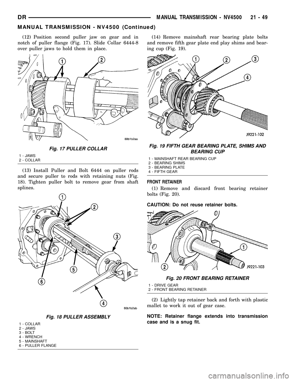
(12) Position second puller jaw on gear and in
notch of puller flange (Fig. 17). Slide Collar 6444-8
over puller jaws to hold them in place.
(13) Install Puller and Bolt 6444 on puller rods
and secure puller to rods with retaining nuts (Fig.
18). Tighten puller bolt to remove gear from shaft
splines.(14) Remove mainshaft rear bearing plate bolts
and remove fifth gear plate end play shims and bear-
ing cup (Fig. 19).
FRONT RETAINER
(1) Remove and discard front bearing retainer
bolts (Fig. 20).
CAUTION: Do not reuse retainer bolts.
(2) Lightly tap retainer back and forth with plastic
mallet to work it out of gear case.
NOTE: Retainer flange extends into transmission
case and is a snug fit.
Fig. 17 PULLER COLLAR
1-JAWS
2 - COLLAR
Fig. 18 PULLER ASSEMBLY
1 - COLLAR
2-JAWS
3 - BOLT
4 - WRENCH
5 - MAINSHAFT
6 - PULLER FLANGE
Fig. 19 FIFTH GEAR BEARING PLATE, SHIMS AND
BEARING CUP
1 - MAINSHAFT REAR BEARING CUP
2 - BEARING SHIMS
3 - BEARING PLATE
4 - FIFTH GEAR
Fig. 20 FRONT BEARING RETAINER
1 - DRIVE GEAR
2 - FRONT BEARING RETAINER
DRMANUAL TRANSMISSION - NV4500 21 - 49
MANUAL TRANSMISSION - NV4500 (Continued)
Page 1753 of 2627
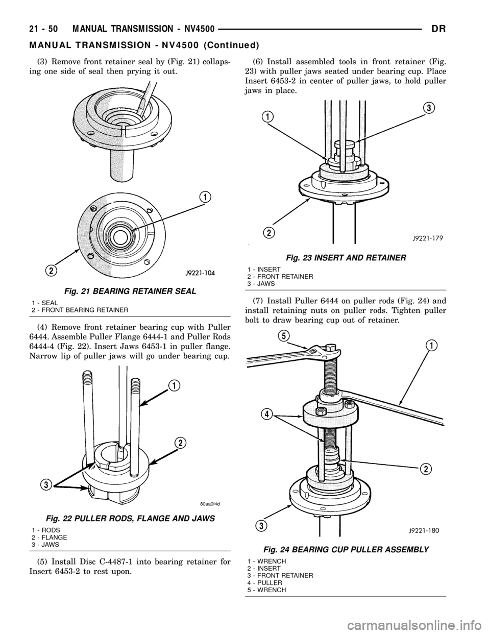
(3) Remove front retainer seal by (Fig. 21) collaps-
ing one side of seal then prying it out.
(4) Remove front retainer bearing cup with Puller
6444. Assemble Puller Flange 6444-1 and Puller Rods
6444-4 (Fig. 22). Insert Jaws 6453-1 in puller flange.
Narrow lip of puller jaws will go under bearing cup.
(5) Install Disc C-4487-1 into bearing retainer for
Insert 6453-2 to rest upon.(6) Install assembled tools in front retainer (Fig.
23) with puller jaws seated under bearing cup. Place
Insert 6453-2 in center of puller jaws, to hold puller
jaws in place.
(7) Install Puller 6444 on puller rods (Fig. 24) and
install retaining nuts on puller rods. Tighten puller
bolt to draw bearing cup out of retainer.
Fig. 21 BEARING RETAINER SEAL
1 - SEAL
2 - FRONT BEARING RETAINER
Fig. 22 PULLER RODS, FLANGE AND JAWS
1 - RODS
2 - FLANGE
3-JAWS
Fig. 23 INSERT AND RETAINER
1 - INSERT
2 - FRONT RETAINER
3-JAWS
Fig. 24 BEARING CUP PULLER ASSEMBLY
1 - WRENCH
2 - INSERT
3 - FRONT RETAINER
4 - PULLER
5 - WRENCH
21 - 50 MANUAL TRANSMISSION - NV4500DR
MANUAL TRANSMISSION - NV4500 (Continued)
Page 1754 of 2627
DRIVE GEAR
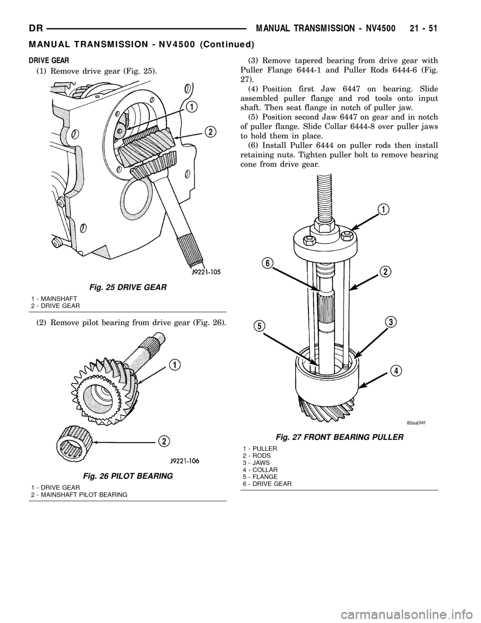
(1) Remove drive gear (Fig. 25).
(2) Remove pilot bearing from drive gear (Fig. 26).(3) Remove tapered bearing from drive gear with
Puller Flange 6444-1 and Puller Rods 6444-6 (Fig.
27).
(4) Position first Jaw 6447 on bearing. Slide
assembled puller flange and rod tools onto input
shaft. Then seat flange in notch of puller jaw.
(5) Position second Jaw 6447 on gear and in notch
of puller flange. Slide Collar 6444-8 over puller jaws
to hold them in place.
(6) Install Puller 6444 on puller rods then install
retaining nuts. Tighten puller bolt to remove bearing
cone from drive gear.
Fig. 25 DRIVE GEAR
1 - MAINSHAFT
2 - DRIVE GEAR
Fig. 26 PILOT BEARING
1 - DRIVE GEAR
2 - MAINSHAFT PILOT BEARING
Fig. 27 FRONT BEARING PULLER
1 - PULLER
2 - RODS
3-JAWS
4 - COLLAR
5 - FLANGE
6 - DRIVE GEAR
DRMANUAL TRANSMISSION - NV4500 21 - 51
MANUAL TRANSMISSION - NV4500 (Continued)
Page 1755 of 2627
MAINSHAFT AND GEARTRAIN
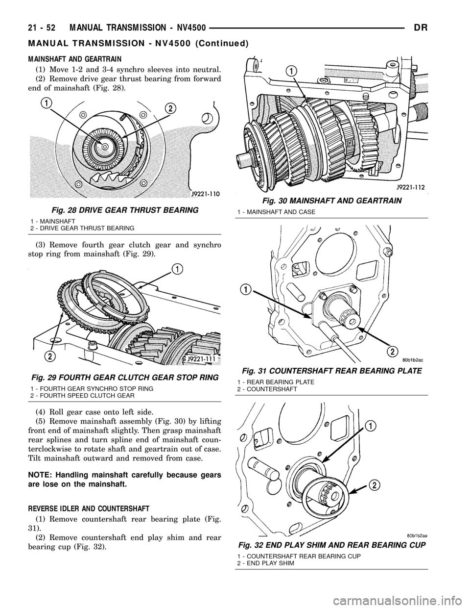
(1) Move 1-2 and 3-4 synchro sleeves into neutral.
(2) Remove drive gear thrust bearing from forward
end of mainshaft (Fig. 28).
(3) Remove fourth gear clutch gear and synchro
stop ring from mainshaft (Fig. 29).
(4) Roll gear case onto left side.
(5) Remove mainshaft assembly (Fig. 30) by lifting
front end of mainshaft slightly. Then grasp mainshaft
rear splines and turn spline end of mainshaft coun-
terclockwise to rotate shaft and geartrain out of case.
Tilt mainshaft outward and removed from case.
NOTE: Handling mainshaft carefully because gears
are lose on the mainshaft.
REVERSE IDLER AND COUNTERSHAFT
(1) Remove countershaft rear bearing plate (Fig.
31).
(2) Remove countershaft end play shim and rear
bearing cup (Fig. 32).
Fig. 28 DRIVE GEAR THRUST BEARING
1 - MAINSHAFT
2 - DRIVE GEAR THRUST BEARING
Fig. 29 FOURTH GEAR CLUTCH GEAR STOP RING
1 - FOURTH GEAR SYNCHRO STOP RING
2 - FOURTH SPEED CLUTCH GEAR
Fig. 30 MAINSHAFT AND GEARTRAIN
1 - MAINSHAFT AND CASE
Fig. 31 COUNTERSHAFT REAR BEARING PLATE
1 - REAR BEARING PLATE
2 - COUNTERSHAFT
Fig. 32 END PLAY SHIM AND REAR BEARING CUP
1 - COUNTERSHAFT REAR BEARING CUP
2 - END PLAY SHIM
21 - 52 MANUAL TRANSMISSION - NV4500DR
MANUAL TRANSMISSION - NV4500 (Continued)
Page 1756 of 2627
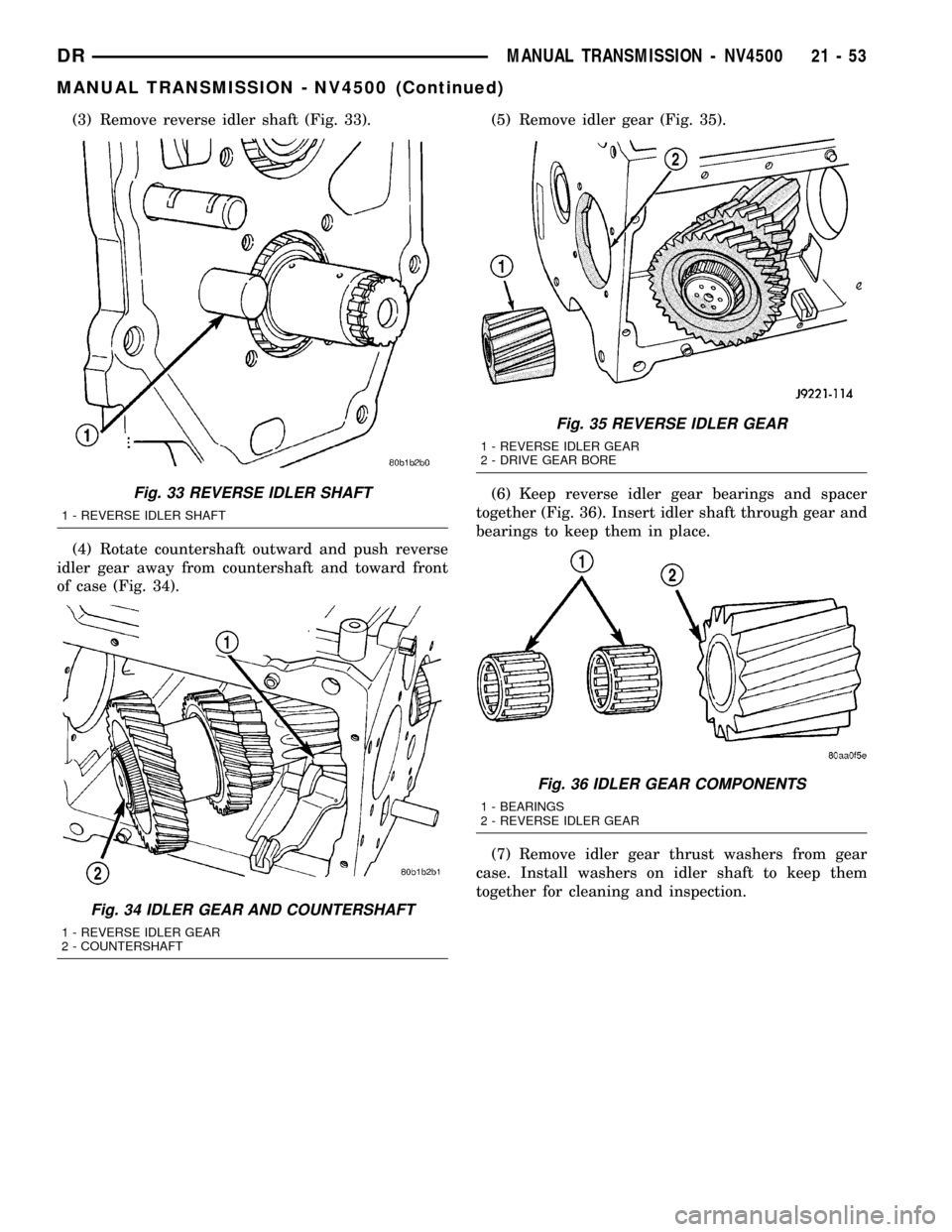
(3) Remove reverse idler shaft (Fig. 33).
(4) Rotate countershaft outward and push reverse
idler gear away from countershaft and toward front
of case (Fig. 34).(5) Remove idler gear (Fig. 35).
(6) Keep reverse idler gear bearings and spacer
together (Fig. 36). Insert idler shaft through gear and
bearings to keep them in place.
(7) Remove idler gear thrust washers from gear
case. Install washers on idler shaft to keep them
together for cleaning and inspection.
Fig. 33 REVERSE IDLER SHAFT
1 - REVERSE IDLER SHAFT
Fig. 34 IDLER GEAR AND COUNTERSHAFT
1 - REVERSE IDLER GEAR
2 - COUNTERSHAFT
Fig. 35 REVERSE IDLER GEAR
1 - REVERSE IDLER GEAR
2 - DRIVE GEAR BORE
Fig. 36 IDLER GEAR COMPONENTS
1 - BEARINGS
2 - REVERSE IDLER GEAR
DRMANUAL TRANSMISSION - NV4500 21 - 53
MANUAL TRANSMISSION - NV4500 (Continued)
Page 1757 of 2627
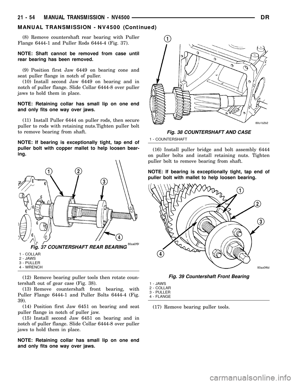
(8) Remove countershaft rear bearing with Puller
Flange 6444-1 and Puller Rods 6444-4 (Fig. 37).
NOTE: Shaft cannot be removed from case until
rear bearing has been removed.
(9) Position first Jaw 6449 on bearing cone and
seat puller flange in notch of puller.
(10) Install second Jaw 6449 on bearing and in
notch of puller flange. Slide Collar 6444-8 over puller
jaws to hold them in place.
NOTE: Retaining collar has small lip on one end
and only fits one way over jaws.
(11) Install Puller 6444 on puller rods, then secure
puller to rods with retaining nuts.Tighten puller bolt
to remove bearing from shaft.
NOTE: If bearing is exceptionally tight, tap end of
puller bolt with copper mallet to help loosen bear-
ing.
(12) Remove bearing puller tools then rotate coun-
tershaft out of gear case (Fig. 38).
(13) Remove countershaft front bearing, with
Puller Flange 6444-1 and Puller Bolts 6444-4 (Fig.
39).
(14) Position first Jaw 6451 on bearing and seat
puller flange in notch of puller jaw.
(15) Install second Jaw 6451 on bearing and in
notch of puller flange. Slide Collar 6444-8 over puller
jaws to hold them in place.
NOTE: Retaining collar has small lip on one end
and only fits one way over jaws.(16) Install puller bridge and bolt assembly 6444
on puller bolts and install retaining nuts. Tighten
puller bolt to remove bearing from shaft.
NOTE: If bearing is exceptionally tight, tap end of
puller bolt with mallet to help loosen bearing.
(17) Remove bearing puller tools.
Fig. 37 COUNTERSHAFT REAR BEARING
1 - COLLAR
2-JAWS
3 - PULLER
4 - WRENCH
Fig. 38 COUNTERSHAFT AND CASE
1 - COUNTERSHAFT
Fig. 39 Countershaft Front Bearing
1-JAWS
2 - COLLAR
3 - PULLER
4 - FLANGE
21 - 54 MANUAL TRANSMISSION - NV4500DR
MANUAL TRANSMISSION - NV4500 (Continued)