relay DODGE RAM 1500 1998 2.G Workshop Manual
[x] Cancel search | Manufacturer: DODGE, Model Year: 1998, Model line: RAM 1500, Model: DODGE RAM 1500 1998 2.GPages: 2627
Page 1139 of 2627
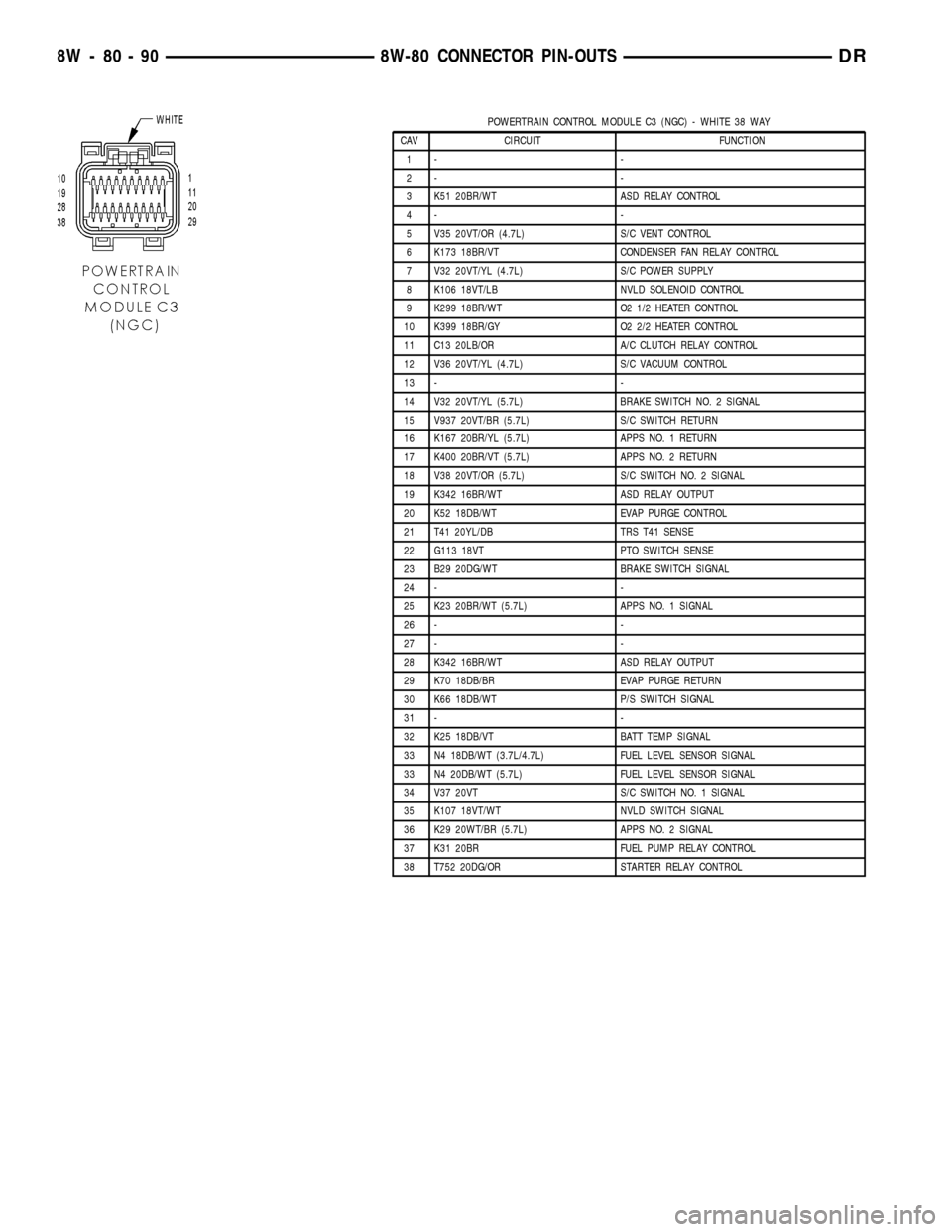
POWERTRAIN CONTROL MODULE C3 (NGC) - WHITE 38 WAY
CAV CIRCUIT FUNCTION
1- -
2- -
3 K51 20BR/WT ASD RELAY CONTROL
4- -
5 V35 20VT/OR (4.7L) S/C VENT CONTROL
6 K173 18BR/VT CONDENSER FAN RELAY CONTROL
7 V32 20VT/YL (4.7L) S/C POWER SUPPLY
8 K106 18VT/LB NVLD SOLENOID CONTROL
9 K299 18BR/WT O2 1/2 HEATER CONTROL
10 K399 18BR/GY O2 2/2 HEATER CONTROL
11 C13 20LB/OR A/C CLUTCH RELAY CONTROL
12 V36 20VT/YL (4.7L) S/C VACUUM CONTROL
13 - -
14 V32 20VT/YL (5.7L) BRAKE SWITCH NO. 2 SIGNAL
15 V937 20VT/BR (5.7L) S/C SWITCH RETURN
16 K167 20BR/YL (5.7L) APPS NO. 1 RETURN
17 K400 20BR/VT (5.7L) APPS NO. 2 RETURN
18 V38 20VT/OR (5.7L) S/C SWITCH NO. 2 SIGNAL
19 K342 16BR/WT ASD RELAY OUTPUT
20 K52 18DB/WT EVAP PURGE CONTROL
21 T41 20YL/DB TRS T41 SENSE
22 G113 18VT PTO SWITCH SENSE
23 B29 20DG/WT BRAKE SWITCH SIGNAL
24 - -
25 K23 20BR/WT (5.7L) APPS NO. 1 SIGNAL
26 - -
27 - -
28 K342 16BR/WT ASD RELAY OUTPUT
29 K70 18DB/BR EVAP PURGE RETURN
30 K66 18DB/WT P/S SWITCH SIGNAL
31 - -
32 K25 18DB/VT BATT TEMP SIGNAL
33 N4 18DB/WT (3.7L/4.7L) FUEL LEVEL SENSOR SIGNAL
33 N4 20DB/WT (5.7L) FUEL LEVEL SENSOR SIGNAL
34 V37 20VT S/C SWITCH NO. 1 SIGNAL
35 K107 18VT/WT NVLD SWITCH SIGNAL
36 K29 20WT/BR (5.7L) APPS NO. 2 SIGNAL
37 K31 20BR FUEL PUMP RELAY CONTROL
38 T752 20DG/OR STARTER RELAY CONTROL
8W - 80 - 90 8W-80 CONNECTOR PIN-OUTSDR
Page 1140 of 2627

POWERTRAIN CONTROL MODULE C4 (NGC) - GREEN 38 WAY
CAV CIRCUIT FUNCTION
1 T60 18YL/GY OVERDRIVE SOLENOID CONTROL
2 T259 18YL/DG 4C SOLENOID CONTROL
3- -
4 T118 18DG MS SOLENOID CONTROL
5- -
6 T219 18YL/LG 2C SOLENOID CONTROL
7- -
8 T59 18YL/LB UNDERDRIVE SOLENOID CONTROL
9- -
10 T20 18DG/WT L/R SOLENOID CONTROL
11 T140 18YL/GY PRESSURE CONTROL SOLENOID CONTROL
12 Z908 18BK GROUND
13 Z977 18BK GROUND
14 Z904 18BK (A/T) GROUND
15 T1 18DG/LB TRS T1 SENSE
16 T3 18DG/DB TRS T3 SENSE
17 T6 18DG TOW/HAUL OVERDRIVE OFF SWITCH SENSE
18 T515 20YL/DB TRANSMISSION CONTROL RELAY CONTROL
19 T16 18YL/OR TRANSMISSION CONTROL RELAY OUTPUT
20 T48 18BR/YL 4C PRESSURE SWITCH SENSE
21 T29 18YL/WT UNDERDRIVE PRESSURE SWITCH SENSE
22 T9 18DG/TN OVERDRIVE PRESSURE SWITCH SENSE
23 - -
24 - -
25 - -
26 T4 18DG/LB TRS T2 SENSE
27 - -
28 T16 18YL/OR TRANSMISSION CONTROL RELAY OUTPUT
29 T50 18YL/TN LOW/REVERSE PRESSURE SWITCH SENSE
30 T147 18DG/YL 2C PRESSURE SWITCH SENSE
31 T38 18YL/BR LINE PRESSURE SENSOR SIGNAL
32 T14 18DG/BR OUTPUT SPEED SENSOR SIGNAL
33 T52 18DG/OR INPUT SPEED SENSOR SIGNAL
34 T13 18DG/VT SPEED SENSOR GROUND
35 T54 18DG/OR TRANSMISSION TEMPERATURE SENSOR SIGNAL
36 - -
37 T42 18DG/YL TRS T42 SENSE
38 T16 18YL/OR TRANSMISSION CONTROL RELAY OUTPUT
DR8W-80 CONNECTOR PIN-OUTS 8W - 80 - 91
Page 1147 of 2627
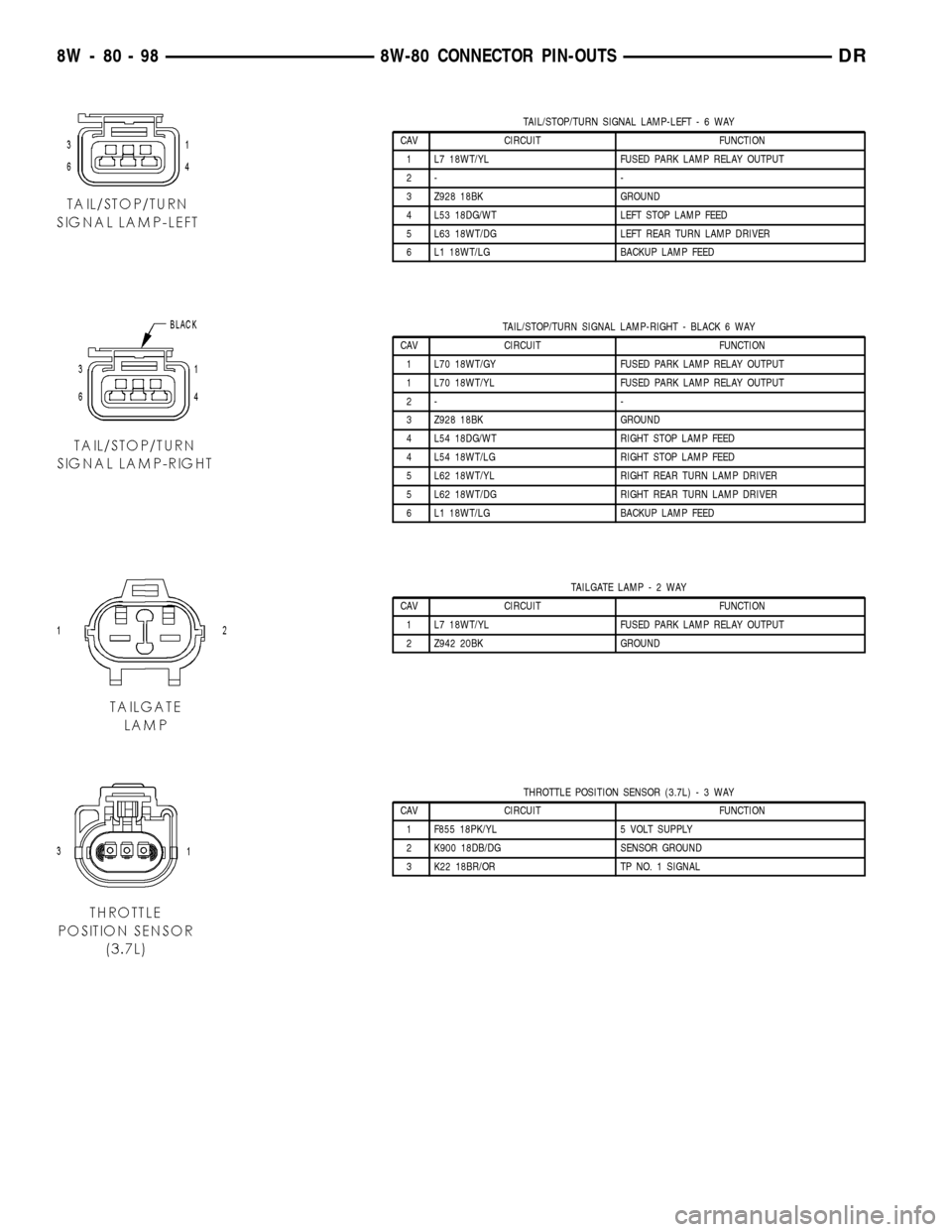
TAIL/STOP/TURN SIGNAL LAMP-LEFT-6WAY
CAV CIRCUIT FUNCTION
1 L7 18WT/YL FUSED PARK LAMP RELAY OUTPUT
2- -
3 Z928 18BK GROUND
4 L53 18DG/WT LEFT STOP LAMP FEED
5 L63 18WT/DG LEFT REAR TURN LAMP DRIVER
6 L1 18WT/LG BACKUP LAMP FEED
TAIL/STOP/TURN SIGNAL LAMP-RIGHT - BLACK 6 WAY
CAV CIRCUIT FUNCTION
1 L70 18WT/GY FUSED PARK LAMP RELAY OUTPUT
1 L70 18WT/YL FUSED PARK LAMP RELAY OUTPUT
2- -
3 Z928 18BK GROUND
4 L54 18DG/WT RIGHT STOP LAMP FEED
4 L54 18WT/LG RIGHT STOP LAMP FEED
5 L62 18WT/YL RIGHT REAR TURN LAMP DRIVER
5 L62 18WT/DG RIGHT REAR TURN LAMP DRIVER
6 L1 18WT/LG BACKUP LAMP FEED
TAILGATE LAMP-2WAY
CAV CIRCUIT FUNCTION
1 L7 18WT/YL FUSED PARK LAMP RELAY OUTPUT
2 Z942 20BK GROUND
THROTTLE POSITION SENSOR (3.7L)-3WAY
CAV CIRCUIT FUNCTION
1 F855 18PK/YL 5 VOLT SUPPLY
2 K900 18DB/DG SENSOR GROUND
3 K22 18BR/OR TP NO. 1 SIGNAL
8W - 80 - 98 8W-80 CONNECTOR PIN-OUTSDR
Page 1148 of 2627
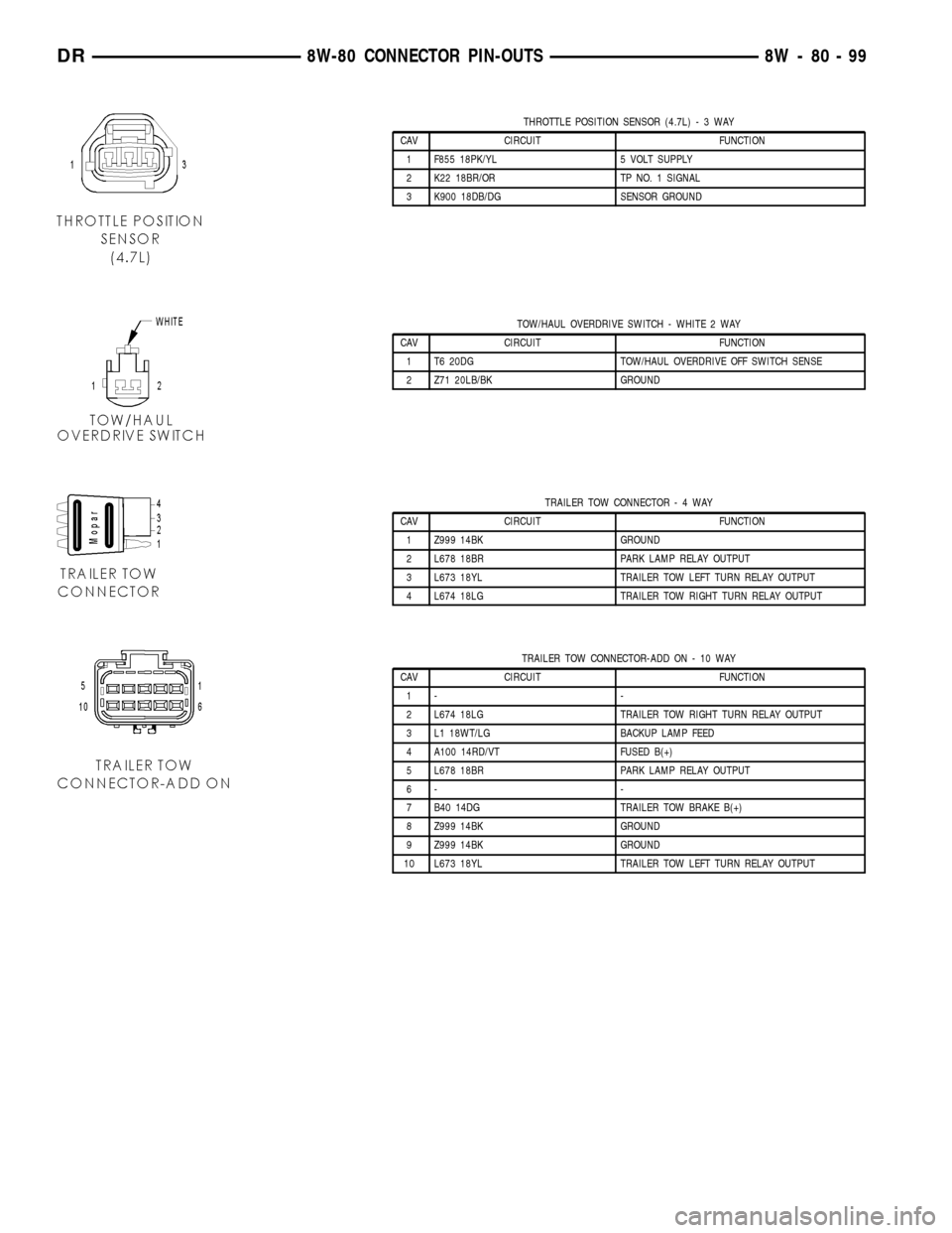
THROTTLE POSITION SENSOR (4.7L)-3WAY
CAV CIRCUIT FUNCTION
1 F855 18PK/YL 5 VOLT SUPPLY
2 K22 18BR/OR TP NO. 1 SIGNAL
3 K900 18DB/DG SENSOR GROUND
TOW/HAUL OVERDRIVE SWITCH - WHITE 2 WAY
CAV CIRCUIT FUNCTION
1 T6 20DG TOW/HAUL OVERDRIVE OFF SWITCH SENSE
2 Z71 20LB/BK GROUND
TRAILER TOW CONNECTOR-4WAY
CAV CIRCUIT FUNCTION
1 Z999 14BK GROUND
2 L678 18BR PARK LAMP RELAY OUTPUT
3 L673 18YL TRAILER TOW LEFT TURN RELAY OUTPUT
4 L674 18LG TRAILER TOW RIGHT TURN RELAY OUTPUT
TRAILER TOW CONNECTOR-ADD ON - 10 WAY
CAV CIRCUIT FUNCTION
1- -
2 L674 18LG TRAILER TOW RIGHT TURN RELAY OUTPUT
3 L1 18WT/LG BACKUP LAMP FEED
4 A100 14RD/VT FUSED B(+)
5 L678 18BR PARK LAMP RELAY OUTPUT
6- -
7 B40 14DG TRAILER TOW BRAKE B(+)
8 Z999 14BK GROUND
9 Z999 14BK GROUND
10 L673 18YL TRAILER TOW LEFT TURN RELAY OUTPUT
DR8W-80 CONNECTOR PIN-OUTS 8W - 80 - 99
Page 1151 of 2627
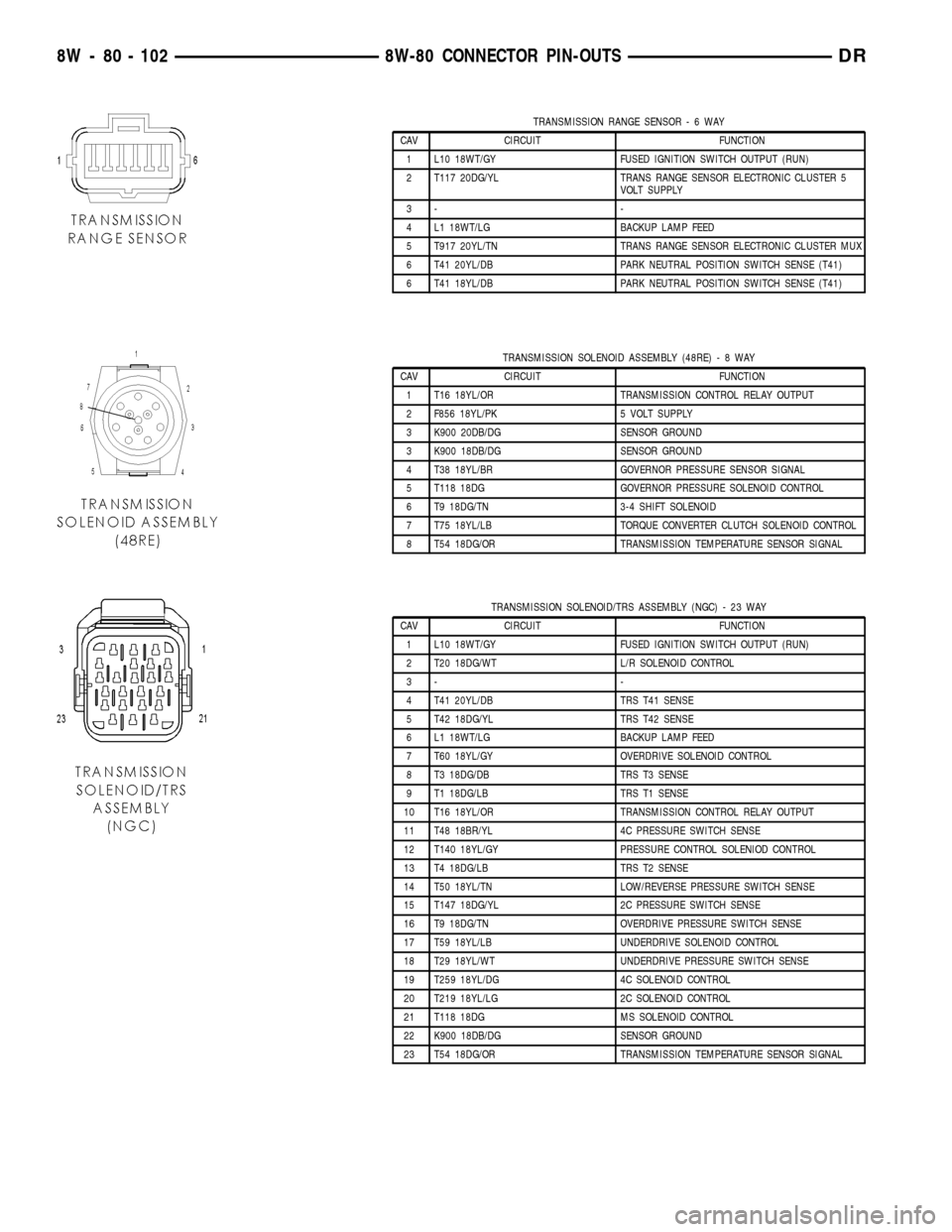
TRANSMISSION RANGE SENSOR-6WAY
CAV CIRCUIT FUNCTION
1 L10 18WT/GY FUSED IGNITION SWITCH OUTPUT (RUN)
2 T117 20DG/YL TRANS RANGE SENSOR ELECTRONIC CLUSTER 5
VOLT SUPPLY
3- -
4 L1 18WT/LG BACKUP LAMP FEED
5 T917 20YL/TN TRANS RANGE SENSOR ELECTRONIC CLUSTER MUX
6 T41 20YL/DB PARK NEUTRAL POSITION SWITCH SENSE (T41)
6 T41 18YL/DB PARK NEUTRAL POSITION SWITCH SENSE (T41)
TRANSMISSION SOLENOID ASSEMBLY (48RE)-8WAY
CAV CIRCUIT FUNCTION
1 T16 18YL/OR TRANSMISSION CONTROL RELAY OUTPUT
2 F856 18YL/PK 5 VOLT SUPPLY
3 K900 20DB/DG SENSOR GROUND
3 K900 18DB/DG SENSOR GROUND
4 T38 18YL/BR GOVERNOR PRESSURE SENSOR SIGNAL
5 T118 18DG GOVERNOR PRESSURE SOLENOID CONTROL
6 T9 18DG/TN 3-4 SHIFT SOLENOID
7 T75 18YL/LB TORQUE CONVERTER CLUTCH SOLENOID CONTROL
8 T54 18DG/OR TRANSMISSION TEMPERATURE SENSOR SIGNAL
TRANSMISSION SOLENOID/TRS ASSEMBLY (NGC) - 23 WAY
CAV CIRCUIT FUNCTION
1 L10 18WT/GY FUSED IGNITION SWITCH OUTPUT (RUN)
2 T20 18DG/WT L/R SOLENOID CONTROL
3- -
4 T41 20YL/DB TRS T41 SENSE
5 T42 18DG/YL TRS T42 SENSE
6 L1 18WT/LG BACKUP LAMP FEED
7 T60 18YL/GY OVERDRIVE SOLENOID CONTROL
8 T3 18DG/DB TRS T3 SENSE
9 T1 18DG/LB TRS T1 SENSE
10 T16 18YL/OR TRANSMISSION CONTROL RELAY OUTPUT
11 T48 18BR/YL 4C PRESSURE SWITCH SENSE
12 T140 18YL/GY PRESSURE CONTROL SOLENIOD CONTROL
13 T4 18DG/LB TRS T2 SENSE
14 T50 18YL/TN LOW/REVERSE PRESSURE SWITCH SENSE
15 T147 18DG/YL 2C PRESSURE SWITCH SENSE
16 T9 18DG/TN OVERDRIVE PRESSURE SWITCH SENSE
17 T59 18YL/LB UNDERDRIVE SOLENOID CONTROL
18 T29 18YL/WT UNDERDRIVE PRESSURE SWITCH SENSE
19 T259 18YL/DG 4C SOLENOID CONTROL
20 T219 18YL/LG 2C SOLENOID CONTROL
21 T118 18DG MS SOLENOID CONTROL
22 K900 18DB/DG SENSOR GROUND
23 T54 18DG/OR TRANSMISSION TEMPERATURE SENSOR SIGNAL
8W - 80 - 102 8W-80 CONNECTOR PIN-OUTSDR
Page 1153 of 2627
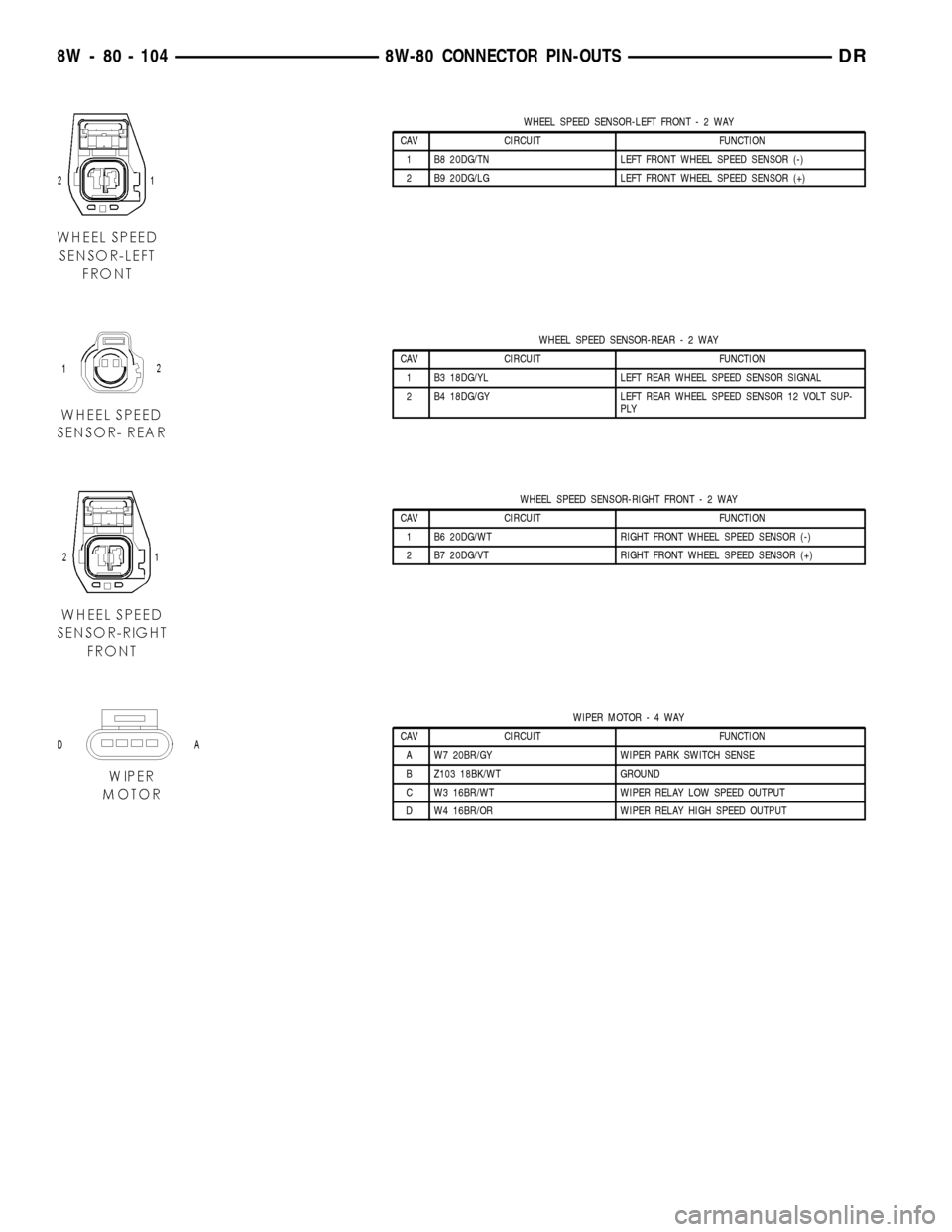
WHEEL SPEED SENSOR-LEFT FRONT-2WAY
CAV CIRCUIT FUNCTION
1 B8 20DG/TN LEFT FRONT WHEEL SPEED SENSOR (-)
2 B9 20DG/LG LEFT FRONT WHEEL SPEED SENSOR (+)
WHEEL SPEED SENSOR-REAR-2WAY
CAV CIRCUIT FUNCTION
1 B3 18DG/YL LEFT REAR WHEEL SPEED SENSOR SIGNAL
2 B4 18DG/GY LEFT REAR WHEEL SPEED SENSOR 12 VOLT SUP-
PLY
WHEEL SPEED SENSOR-RIGHT FRONT-2WAY
CAV CIRCUIT FUNCTION
1 B6 20DG/WT RIGHT FRONT WHEEL SPEED SENSOR (-)
2 B7 20DG/VT RIGHT FRONT WHEEL SPEED SENSOR (+)
WIPER MOTOR-4WAY
CAV CIRCUIT FUNCTION
A W7 20BR/GY WIPER PARK SWITCH SENSE
B Z103 18BK/WT GROUND
C W3 16BR/WT WIPER RELAY LOW SPEED OUTPUT
D W4 16BR/OR WIPER RELAY HIGH SPEED OUTPUT
8W - 80 - 104 8W-80 CONNECTOR PIN-OUTSDR
Page 1158 of 2627
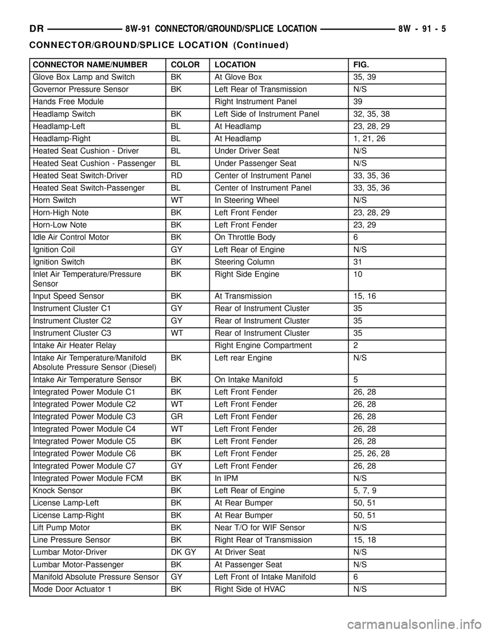
CONNECTOR NAME/NUMBER COLOR LOCATION FIG.
Glove Box Lamp and Switch BK At Glove Box 35, 39
Governor Pressure Sensor BK Left Rear of Transmission N/S
Hands Free Module Right Instrument Panel 39
Headlamp Switch BK Left Side of Instrument Panel 32, 35, 38
Headlamp-Left BL At Headlamp 23, 28, 29
Headlamp-Right BL At Headlamp 1, 21, 26
Heated Seat Cushion - Driver BL Under Driver Seat N/S
Heated Seat Cushion - Passenger BL Under Passenger Seat N/S
Heated Seat Switch-Driver RD Center of Instrument Panel 33, 35, 36
Heated Seat Switch-Passenger BL Center of Instrument Panel 33, 35, 36
Horn Switch WT In Steering Wheel N/S
Horn-High Note BK Left Front Fender 23, 28, 29
Horn-Low Note BK Left Front Fender 23, 29
Idle Air Control Motor BK On Throttle Body 6
Ignition Coil GY Left Rear of Engine N/S
Ignition Switch BK Steering Column 31
Inlet Air Temperature/Pressure
SensorBK Right Side Engine 10
Input Speed Sensor BK At Transmission 15, 16
Instrument Cluster C1 GY Rear of Instrument Cluster 35
Instrument Cluster C2 GY Rear of Instrument Cluster 35
Instrument Cluster C3 WT Rear of Instrument Cluster 35
Intake Air Heater Relay Right Engine Compartment 2
Intake Air Temperature/Manifold
Absolute Pressure Sensor (Diesel)BK Left rear Engine N/S
Intake Air Temperature Sensor BK On Intake Manifold 5
Integrated Power Module C1 BK Left Front Fender 26, 28
Integrated Power Module C2 WT Left Front Fender 26, 28
Integrated Power Module C3 GR Left Front Fender 26, 28
Integrated Power Module C4 WT Left Front Fender 26, 28
Integrated Power Module C5 BK Left Front Fender 26, 28
Integrated Power Module C6 BK Left Front Fender 25, 26, 28
Integrated Power Module C7 GY Left Front Fender 26, 28
Integrated Power Module FCM BK In IPM N/S
Knock Sensor BK Left Rear of Engine 5, 7, 9
License Lamp-Left BK At Rear Bumper 50, 51
License Lamp-Right BK At Rear Bumper 50, 51
Lift Pump Motor BK Near T/O for WIF Sensor N/S
Line Pressure Sensor BK Right Rear of Transmission 15, 18
Lumbar Motor-Driver DK GY At Driver Seat N/S
Lumbar Motor-Passenger BK At Passenger Seat N/S
Manifold Absolute Pressure Sensor GY Left Front of Intake Manifold 6
Mode Door Actuator 1 BK Right Side of HVAC N/S
DR8W-91 CONNECTOR/GROUND/SPLICE LOCATION 8W - 91 - 5
CONNECTOR/GROUND/SPLICE LOCATION (Continued)
Page 1216 of 2627

8W-97 POWER DISTRIBUTION
TABLE OF CONTENTS
page page
POWER DISTRIBUTION
DESCRIPTION..........................1
OPERATION............................1
SPECIAL TOOLS
POWER DISTRIBUTION SYSTEMS.........2
CIGAR LIGHTER OUTLET
DESCRIPTION..........................2
OPERATION............................2
DIAGNOSIS AND TESTING - CIGAR LIGHTER
OUTLET.............................2
INTEGRATED POWER MODULE
DESCRIPTION..........................3
OPERATION............................3
REMOVAL.............................3
INSTALLATION..........................4
FRONT CONTROL MODULE
DESCRIPTION..........................5OPERATION............................5
DIAGNOSIS AND TESTING - FRONT
CONTROL MODULE....................5
REMOVAL.............................6
INSTALLATION..........................6
IOD FUSE
DESCRIPTION..........................6
OPERATION............................6
REMOVAL.............................7
INSTALLATION..........................7
POWER OUTLET
DESCRIPTION..........................7
OPERATION............................7
DIAGNOSIS AND TESTING - POWER
OUTLET.............................7
REMOVAL.............................8
INSTALLATION..........................8
POWER DISTRIBUTION
DESCRIPTION
This group covers the various standard and
optional power distribution components used on this
model. The power distribution system for this vehicle
consists of the following components:
²Integrated Power Module (IPM)
²Front Control Module (FCM)
²Power Distribution Center (PDC)
²Power Outlets
²Cigar Lighter Outlets
²Relays
Refer to Wiring Diagrams for complete circuit sche-
matics.
The power distribution system also incorporates
various types of circuit control and protection fea-
tures, including:
²Automatic resetting circuit breakers
²Blade-type fuses
²Cartridge fuses
²Relays
Following are general descriptions of the major
components in the power distribution system. See the
owner's manual in the vehicle glove box for more
information on the features and use of all of the
power distribution system components.
OPERATION
The power distribution system for this vehicle is
designed to provide safe, reliable, and centralized dis-
tribution points for the electrical current required to
operate all of the many standard and optional facto-
ry-installed electrical and electronic powertrain,
chassis, safety, security, comfort and convenience sys-
tems. At the same time, the power distribution sys-
tem was designed to provide ready access to these
electrical distribution points for the vehicle techni-
cian to use when conducting diagnosis and repair of
faulty circuits. The power distribution system can
also prove useful for the sourcing of additional elec-
trical circuits that may be required to provide the
electrical current needed to operate many accessories
that the vehicle owner may choose to have installed
in the aftermarket.
DR8W-97 POWER DISTRIBUTION 8W - 97 - 1
Page 1218 of 2627

INTEGRATED POWER MODULE
DESCRIPTION
The Integrated Power Module (IPM) (Fig. 1) is a
combination of the Power Distribution Center (PDC)
and the Front Control Module (FCM). The IPM is
located in the engine compartment, next to the bat-
tery on this model. The power distribution center
mates directly with the Front Control Module (FCM)
to form the Integrated Power Module Fuse and Relay
Center. The power distribution center (PDC) is a
printed circuit board based module that contains
fuses and relays, while the front control module con-
tains the electronics controlling the integrated power
module and other functions. This integrated power
module connects directly to the battery positive via a
stud located on top of the unit. The ground connec-
tion is via electrical connectors. The integrated power
module provides the primary means of voltage distri-
bution and protection for the entire vehicle.
The molded plastic integrated power module hous-
ing includes a base and cover. The integrated power
module cover is easily opened or removed for service
access by unscrewing the cover retaining nut and has
a fuse and relay layout map integral to the inside
surface of the cover. This integrated power module
housing base and cover are secured in place via bolts
to the left front fender support assembly.
Replaceable components of the integrated power
module assembly are broken down into the followingcomponents: the Power Distribution Center (PDC),
the integrated power module cover, the Front Control
Module (FCM) and the Integrated Power Module
Assembly which includes the power distribution cen-
ter, the cover and FCM.Refer to the Front Con-
trol Module in the Electronic Control Module
sectionof this service manual for information on the
front control module.
OPERATION
All of the current from the battery and the gener-
ator output enters the integrated power module via a
stud on the top of the module. The integrated power
module cover is removed to access the fuses or relays.
Internal connections of all of the power distribution
center circuits is accomplished by a combination of
bus bars and a printed circuit board. Refer to the
Wiring section of the service manual for complete
integrated power module circuit schematics.
REMOVAL
(1) Disconnect the negative and positive battery
cables.
(2) Unsnap cover and remove the B+ terminal nut
from the integrated power module B+ terminal.
Remove the B+ cable from the integrated power mod-
ule.
(3) Disconnect the gray connector from the inte-
grated power module.
Fig. 1 DR INTEGRATED POWER MODULE
1 - POWER DISTRIBUTION CENTER HOUSING
2 - FRONT CONTROL MODULE ELECTRICAL CONNECTOR
Fig. 2 DR INTEGRATED POWER MODULE
1 - COVER RETAINING BOLT
2 - INTEGRATED POWER MODULE RETAINING BOLT
3 - RETAINING SCREW
4 - INTEGRATED POWER MODULE COVER
DR8W-97 POWER DISTRIBUTION 8W - 97 - 3
Page 1220 of 2627

(3) Connect the electrical connectors by pushing
straight on and rotating the connector arm inboard,
until the connector is firmly locked in place on the
module assembly.
(4) Grasp the integrated power module with two
hands and install the assembly on the battery tray
(Fig. 5).
(5) Install the integrated power module retaining
bolt and screw.
(6) Connect the gray connector on the integrated
power module housing.
(7) Install the B+ terminal cable and nut on the
integrated power module B+ terminal. Snap the
cover in place.
(8) Connect the negative and positive battery
cables.
FRONT CONTROL MODULE
DESCRIPTION
The Front Control Module (FCM) is a micro con-
troller based module located in the left front corner
of the engine compartment. On this model the inte-
grated power module must be positioned aside in
order to access the front control module. The front
control module mates to the power distribution cen-
ter to form the Integrated Power Module (IPM). Theintegrated power module connects directly to the bat-
tery and provides the primary means of circuit pro-
tection and power distribution for all vehicle
electrical systems. The front control module controls
power to some of these vehicle systems electrical and
electromechanical loads based on inputs received
from hard wired switch inputs and data received on
the PCI bus circuit (J1850).
For information on theIntegrated Power Mod-
ule Refer to the Power Distribution Sectionof
the service manual.
OPERATION
As messages are sent over the PCI bus circuit, the
front control module reads these messages and con-
trols power to some of the vehicles electrical systems
by completing the circuit to ground (low side driver)
or completing the circuit to 12 volt power (high side
driver). The following functions areControlledby
the Front Control Module:
²Headlamp Power with Voltage Regulation
²Windshield Wiper ªON/OFFº Relay Actuation
²Windshield Wiper ªHI/LOº Relay Actuation
²Windshield Washer Pump Motor
²Fog Lamp Relay Actuation
²Park Lamp Relay Actuation
²Horn Relay Actuation
The following inputs areReceived/Monitoredby
the Front Control Module:
²B+ Connection Detection
²Power Ground
²Ambient Temperature Sensing
²Ignition Switch Run
²Washer Fluid Level Switch
²Windshield Wiper Park Switch
²PCI Bus Circuit
DIAGNOSIS AND TESTING - FRONT CONTROL
MODULE
The front control module is a printed circuit board
based module with a on-board micro-processor. The
front control module interfaces with other electronic
modules in the vehicle via the Programmable Com-
munications Interface (PCI) data bus (J1850). In
order to obtain conclusive testing the Programmable
Communications Interface (PCI) data bus network
and all of the electronic modules that provide inputs
to, or receive outputs from the front control module
must be checked. All PCI (J1850) communication
faults must be resolved prior to further diagnosing
any front control module related issues.
The front control module was designed to be diag-
nosed with an appropriate diagnostic scan tool, such
as the DRB IIIt. The most reliable, efficient, and
accurate means to diagnose the front control module
Fig. 5 INTEGRATED POWER MODULE MOUNTING
TABS
1 - INTEGRATED POWER MODULE MOUNTING HOLES
2 - BATTERY TRAY ASSEMBLY
3 - FRONT CONTROL MODULE
DR8W-97 POWER DISTRIBUTION 8W - 97 - 5
INTEGRATED POWER MODULE (Continued)