Connector location DODGE RAM 1500 1998 2.G Workshop Manual
[x] Cancel search | Manufacturer: DODGE, Model Year: 1998, Model line: RAM 1500, Model: DODGE RAM 1500 1998 2.GPages: 2627
Page 1495 of 2627
(6) Remove the wooden dowel rods and rubber
bands from the tappets.
(7) Lubricate the push rods with engine oil and
install in their original location.Verify that they
are seated in the tappets.
(8) Lubricate the valve tips with engine oil and
install the crossheads in their original locations.
(9) Lubricate the crossheads and push rod sockets
with engine oil and install the rocker arms and ped-
estals in their original locations. Tighten bolts to 36
N´m (27 ft. lbs.) torque.
(10)Verify valve lash adjustment (Refer to 9 -
ENGINE/CYLINDER HEAD/INTAKE/EXHAUST
VALVES & SEATS - STANDARD PROCEDURE).
(11) Install the cylinder head cover and reusable
gasket (Refer to 9 - ENGINE/CYLINDER HEAD/
CYLINDER HEAD COVER(S) - INSTALLATION).
(12) Install gear housing cover (Refer to 9 -
ENGINE/VALVE TIMING/GEAR HOUSING COVER
- INSTALLATION). Install front crankshaft dust
seal.
(13) Install the crankshaft damper with the speed
indicator ring (Refer to 9 - ENGINE/ENGINE
BLOCK/VIBRATION DAMPER - INSTALLATION).
(14) Install the fan support/hub assembly Refer to
(Refer to 7 - COOLING/ENGINE/RADIATOR FAN -
INSTALLATION).
(15) Install the power steering pump.
(16) Install accessory drive belt tensioner. Torque
bolt to 43 Nm (32 ft. lbs.).
(17) Install the accessory drive belt (Refer to 7 -
COOLING/ACCESSORY DRIVE/DRIVE BELTS -
INSTALLATION).
(18) Install the charge air cooler (with a/c con-
denser and auxiliary transmission oil cooler, if
equipped) and tighten the mounting bolts to 2 N´m
(17 in. lbs.) torque.
(19) Connect charge air cooler inlet and outlet
pipes. Tighten clamps to 11 N´m (95 in. lbs.) torque.
(20) Install the radiator upper support panel.
(21) Close radiator petcock and lower the radiator
into the engine compartment. Tighten the mounting
bolts to 11 N´m (95 in. lbs.) torque.
(22) Raise vehicle on hoist.
(23) Connect radiator lower hose and install
clamp.
(24) Connect transmission auxiliary oil cooler lines
(if equipped).
(25) Lower vehicle.
(26) Install the fan shroud and tighten the mount-
ing screws to 6 N´m (50 in. lbs.) torque.
(27) Install the electronically controlled viscous
fan/drive assembly. Connect harness connector.(Refer
to 7 - COOLING/ENGINE/RADIATOR FAN -
INSTALLATION).(28) Install the coolant recovery and windshield
washer fluid reservoirs to the fan shroud.
(29) Connect the coolant recovery hose to the radi-
ator filler neck.
(30) Add engine coolant (Refer to 7 - COOLING -
STANDARD PROCEDURE).
(31) Charge A/C system with refrigerant (if A/C
equipped) (Refer to 24 - HEATING & AIR CONDI-
TIONING/PLUMBING - STANDARD PROCEDURE).
(32) Connect the battery negative cables.
(33) Start engine and check for engine oil and cool-
ant leaks.
CONNECTING ROD BEARINGS
STANDARD PROCEDURE - CONNECTING ROD
BEARING AND CRANKSHAFT JOURNAL
CLEARANCE
(1) Measure the connecting rod bore with bearings
removedand the bolts tightened to 100 N´m (73 ft.
lbs.) torque..
(2) Measure the connecting rod bore with the bear-
ingsinstalledand the bolts tightened to 100 N´m
(73 ft. lbs.) torque.
Measure within 20É arc from each side of the part-
ing line. Also measure 90É from parting line.
Record the smallest and largest diameter.
Measure the diameter of the rod journal at the
location shown (Fig. 63). Calculate the average diam-
eter for each side of the journal.
Determine minimum bearing clearance by calculat-
ing the differance between the smallest connecting
rod bore diameter with the bearing installed and the
average diameter for each side of the crankshaft jour-
nal.
Determine the maximum bearing clearance by cal-
culating the difference between the largest connect-
ing rod bore diameter and the average diameter with
the bearing installed for each side of the crankshaft
journal.
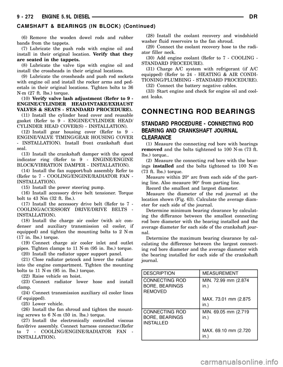
DESCRIPTION MEASUREMENT
CONNECTING ROD
BORE, BEARINGS
REMOVEDMIN. 72.99 mm (2.874
in.)
MAX. 73.01 mm (2.875
in.)
CONNECTING ROD
BORE, BEARINGS
INSTALLEDMIN. 69.05 mm (2.719
in.)
MAX. 69.10 mm (2.720
in.)
9 - 272 ENGINE 5.9L DIESELDR
CAMSHAFT & BEARINGS (IN BLOCK) (Continued)
Page 1521 of 2627
INSTALLATION
(1) Using a new gasket, install the intake manifold
cover.
(2) Install the cover-to-cylinder head bolts that do
not hold down the fuel rail. Tighten the bolts to 24
N´m (18 ft. lbs.) torque.
(3) Install the high pressure rail and fuel lines
(Refer to 14 - FUEL SYSTEM/FUEL DELIVERY/
FUEL LINES - INSTALLATION).
(4) Using two (2) new gaskets, install the intake
air grid heater and air inlet housing. Position the
ground cable and install and tighten the bolts to 24
N´m (18 ft. lbs.) torque.
(5) Connect the manifold air temperature/pressure
sensor connector.
(6) Install and tighten the air intake heater power
supply nuts to 14 N´m (120 in. lbs.) torque.
(7) Install the APPS bracket. Torque fasteners to
43 N´m (32ft lbs.) torque.
(8) Install oil dipstick tube support at fuel filter
housing.
(9) Install the engine oil dipstick tube and mount-
ing bolt.
(10) Position the charge air cooler outlet tube onto
the air inlet housing. Tighten the clamps to 11 N´m
(100 in. lbs.) torque.
(11) Attach the engine wire harness to the air inlet
housing at two locations.
(12) Prime the fuel system. Refer to the fuel prim-
ing procedure in Group 14, Fuel System.
(13) Connect the battery negative cables.
EXHAUST MANIFOLD
REMOVAL
(1) Disconnect the battery negative cables.
(2) Raise vehicle on hoist.
(3) Disconnect the exhaust pipe from the turbo-
charger elbow.
(4) Disconnect oil drain tube from turbocharger.
(5) Lower vehicle.
(6) Disconnect the turbocharger air inlet hose.
(7) Remove air cleaner assembly.
(8) Disconnect the turbocharger oil supply line.
(9) Disconnect the charge air cooler inlet pipe from
the turbocharger.
(10) Remove the turbocharger and gasket from the
exhaust manifold.
(11) Remove the cab heater return pipe nuts from
the exhaust manifold stud. Position the tube out of
the way.
(12) Remove heat shield.
(13) Remove exhaust manifold bolt lockplates.
(14) Remove the exhaust manifold-to-cylinder head
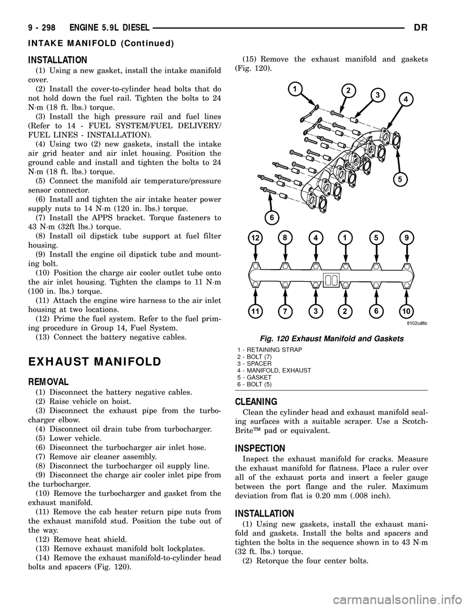
bolts and spacers (Fig. 120).(15) Remove the exhaust manifold and gaskets
(Fig. 120).
CLEANING
Clean the cylinder head and exhaust manifold seal-
ing surfaces with a suitable scraper. Use a Scotch-
BriteŸ pad or equivalent.
INSPECTION
Inspect the exhaust manifold for cracks. Measure
the exhaust manifold for flatness. Place a ruler over
all of the exhaust ports and insert a feeler gauge
between the port flange and the ruler. Maximum
deviation from flat is 0.20 mm (.008 inch).
INSTALLATION
(1) Using new gaskets, install the exhaust mani-
fold and gaskets. Install the bolts and spacers and
tighten the bolts in the sequence shown in to 43 N´m
(32 ft. lbs.) torque.
(2) Retorque the four center bolts.
Fig. 120 Exhaust Manifold and Gaskets
1 - RETAINING STRAP
2 - BOLT (7)
3 - SPACER
4 - MANIFOLD, EXHAUST
5 - GASKET
6 - BOLT (5)
9 - 298 ENGINE 5.9L DIESELDR
INTAKE MANIFOLD (Continued)
Page 1572 of 2627
(2) Remove fuel pump relay from Power Distribu-
tion Center (PDC). For location of relay, refer to label
on underside of PDC cover.
(3) Start and run engine until it stalls.
(4) Attempt restarting engine until it will no
longer run.
(5) Turn ignition key to OFF position.
CAUTION: Steps 1, 2, 3 and 4 must be performed to
relieve high pressure fuel from within fuel rail. Do
not attempt to use following steps to relieve this
pressure as excessive fuel will be forced into a cyl-
inder chamber.
(6) Unplug connector from any fuel injector.
(7) Attach one end of a jumper wire with alligator
clips (18 gauge or smaller) to either injector terminal.
(8) Connect other end of jumper wire to positive
side of battery.(9) Connect one end of a second jumper wire to
remaining injector terminal.
CAUTION: Powering an injector for more than a few
seconds will permanently damage the injector.
(10) Momentarily touch other end of jumper wire
to negative terminal of battery for no more than a
few seconds.
(11) Place a rag or towel below fuel line quick-con-
nect fitting at fuel rail.
(12) Disconnect quick-connect fitting at fuel rail.
Refer to Quick-Connect Fittings.
(13) Return fuel pump relay to PDC.
(14) One or more Diagnostic Trouble Codes (DTC's)
may have been stored in PCM memory due to fuel
pump relay removal. The DRBtscan tool must be
used to erase a DTC.
SPECIFICATIONS
FUEL SYSTEM PRESSURE
58 psi +/- 2 psi
TORQUE - FUEL SYSTEM - EXCEPT DIESEL
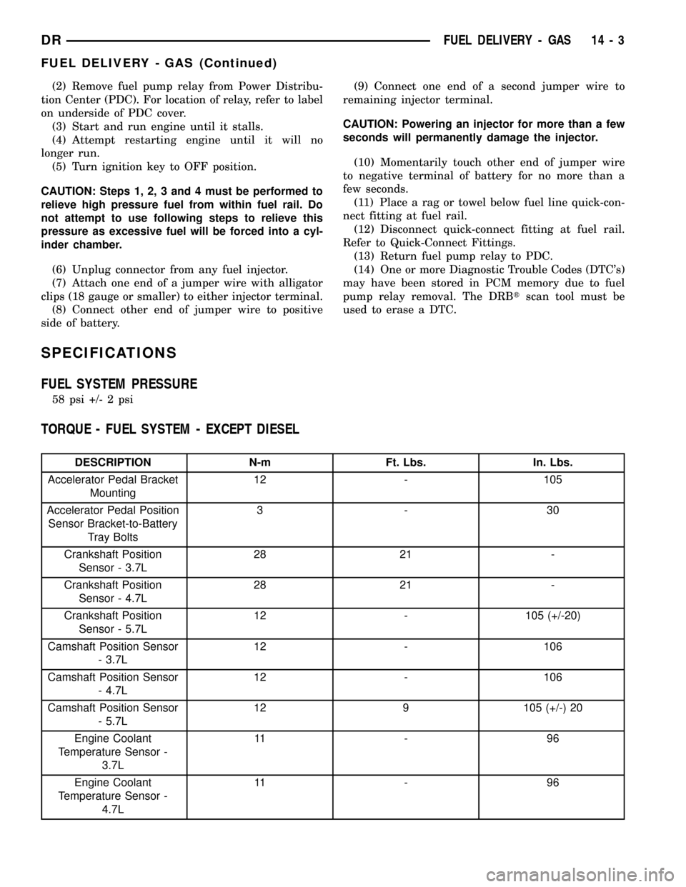
DESCRIPTION N-m Ft. Lbs. In. Lbs.
Accelerator Pedal Bracket
Mounting12 - 105
Accelerator Pedal Position
Sensor Bracket-to-Battery
Tray Bolts3-30
Crankshaft Position
Sensor - 3.7L28 21 -
Crankshaft Position
Sensor - 4.7L28 21 -
Crankshaft Position
Sensor - 5.7L12 - 105 (+/-20)
Camshaft Position Sensor
- 3.7L12 - 106
Camshaft Position Sensor
- 4.7L12 - 106
Camshaft Position Sensor
- 5.7L12 9 105 (+/-) 20
Engine Coolant
Temperature Sensor -
3.7L11 - 9 6
Engine Coolant
Temperature Sensor -
4.7L11 - 9 6
DRFUEL DELIVERY - GAS 14 - 3
FUEL DELIVERY - GAS (Continued)
Page 1576 of 2627
REMOVAL
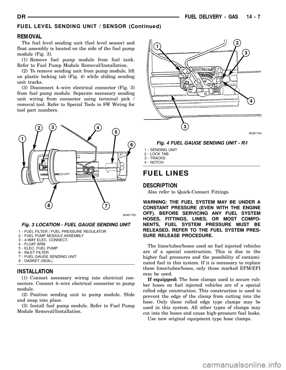
The fuel level sending unit (fuel level sensor) and
float assembly is located on the side of the fuel pump
module (Fig. 3).
(1) Remove fuel pump module from fuel tank.
Refer to Fuel Pump Module Removal/Installation.
(2) To remove sending unit from pump module, lift
on plastic locking tab (Fig. 4) while sliding sending
unit tracks.
(3) Disconnect 4±wire electrical connector (Fig. 3)
from fuel pump module. Separate necessary sending
unit wiring from connector using terminal pick /
removal tool. Refer to Special Tools in 8W Wiring for
tool part numbers.
INSTALLATION
(1) Connect necessary wiring into electrical con-
nectors. Connect 4±wire electrical connector to pump
module.
(2) Position sending unit to pump module. Slide
and snap into place.
(3) Install fuel pump module. Refer to Fuel Pump
Module Removal/Installation.
FUEL LINES
DESCRIPTION
Also refer to Quick-Connect Fittings.
WARNING: THE FUEL SYSTEM MAY BE UNDER A
CONSTANT PRESSURE (EVEN WITH THE ENGINE
OFF). BEFORE SERVICING ANY FUEL SYSTEM
HOSES, FITTINGS, LINES, OR MOST COMPO-
NENTS, FUEL SYSTEM PRESSURE MUST BE
RELEASED. REFER TO THE FUEL SYSTEM PRES-
SURE RELEASE PROCEDURE.
The lines/tubes/hoses used on fuel injected vehicles
are of a special construction. This is due to the
higher fuel pressures and the possibility of contami-
nated fuel in this system. If it is necessary to replace
these lines/tubes/hoses, only those marked EFM/EFI
may be used.
If equipped:The hose clamps used to secure rub-
ber hoses on fuel injected vehicles are of a special
rolled edge construction. This construction is used to
prevent the edge of the clamp from cutting into the
hose. Only these rolled edge type clamps may be
used in this system. All other types of clamps may
cut into the hoses and cause high-pressure fuel leaks.
Use new original equipment type hose clamps.
Fig. 3 LOCATION - FUEL GAUGE SENDING UNIT
1 - FUEL FILTER / FUEL PRESSURE REGULATOR
2 - FUEL PUMP MODULE ASSEMBLY
3 - 4-WAY ELEC. CONNECT.
4 - FLOAT ARM
5 - ELEC. FUEL PUMP
6 - INLET FILTER
7 - FUEL GAUGE SENDING UNIT
8 - GASKET (SEAL)
Fig. 4 FUEL GAUGE SENDING UNIT - R/I
1 - SENDING UNIT
2 - LOCK TAB
3 - TRACKS
4 - NOTCH
DRFUEL DELIVERY - GAS 14 - 7
FUEL LEVEL SENDING UNIT / SENSOR (Continued)
Page 1582 of 2627
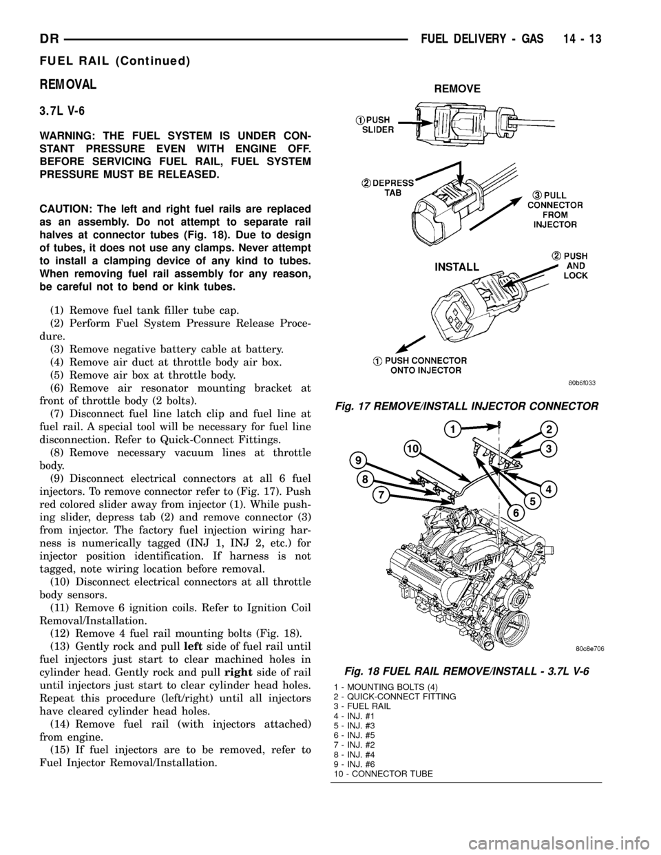
REMOVAL
3.7L V-6
WARNING: THE FUEL SYSTEM IS UNDER CON-
STANT PRESSURE EVEN WITH ENGINE OFF.
BEFORE SERVICING FUEL RAIL, FUEL SYSTEM
PRESSURE MUST BE RELEASED.
CAUTION: The left and right fuel rails are replaced
as an assembly. Do not attempt to separate rail
halves at connector tubes (Fig. 18). Due to design
of tubes, it does not use any clamps. Never attempt
to install a clamping device of any kind to tubes.
When removing fuel rail assembly for any reason,
be careful not to bend or kink tubes.
(1) Remove fuel tank filler tube cap.
(2) Perform Fuel System Pressure Release Proce-
dure.
(3) Remove negative battery cable at battery.
(4) Remove air duct at throttle body air box.
(5) Remove air box at throttle body.
(6) Remove air resonator mounting bracket at
front of throttle body (2 bolts).
(7) Disconnect fuel line latch clip and fuel line at
fuel rail. A special tool will be necessary for fuel line
disconnection. Refer to Quick-Connect Fittings.
(8) Remove necessary vacuum lines at throttle
body.
(9) Disconnect electrical connectors at all 6 fuel
injectors. To remove connector refer to (Fig. 17). Push
red colored slider away from injector (1). While push-
ing slider, depress tab (2) and remove connector (3)
from injector. The factory fuel injection wiring har-
ness is numerically tagged (INJ 1, INJ 2, etc.) for
injector position identification. If harness is not
tagged, note wiring location before removal.
(10) Disconnect electrical connectors at all throttle
body sensors.
(11) Remove 6 ignition coils. Refer to Ignition Coil
Removal/Installation.
(12) Remove 4 fuel rail mounting bolts (Fig. 18).
(13) Gently rock and pullleftside of fuel rail until
fuel injectors just start to clear machined holes in
cylinder head. Gently rock and pullrightside of rail
until injectors just start to clear cylinder head holes.
Repeat this procedure (left/right) until all injectors
have cleared cylinder head holes.
(14) Remove fuel rail (with injectors attached)
from engine.
(15) If fuel injectors are to be removed, refer to
Fuel Injector Removal/Installation.
Fig. 17 REMOVE/INSTALL INJECTOR CONNECTOR
Fig. 18 FUEL RAIL REMOVE/INSTALL - 3.7L V-6
1 - MOUNTING BOLTS (4)
2 - QUICK-CONNECT FITTING
3 - FUEL RAIL
4 - INJ. #1
5 - INJ. #3
6 - INJ. #5
7 - INJ. #2
8 - INJ. #4
9 - INJ. #6
10 - CONNECTOR TUBE
DRFUEL DELIVERY - GAS 14 - 13
FUEL RAIL (Continued)
Page 1583 of 2627
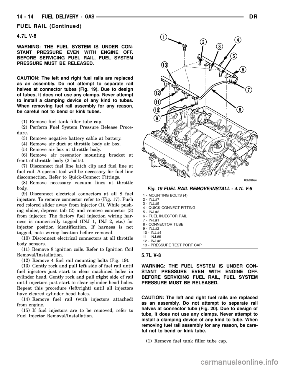
4.7L V-8
WARNING: THE FUEL SYSTEM IS UNDER CON-
STANT PRESSURE EVEN WITH ENGINE OFF.
BEFORE SERVICING FUEL RAIL, FUEL SYSTEM
PRESSURE MUST BE RELEASED.
CAUTION: The left and right fuel rails are replaced
as an assembly. Do not attempt to separate rail
halves at connector tubes (Fig. 19). Due to design
of tubes, it does not use any clamps. Never attempt
to install a clamping device of any kind to tubes.
When removing fuel rail assembly for any reason,
be careful not to bend or kink tubes.
(1) Remove fuel tank filler tube cap.
(2) Perform Fuel System Pressure Release Proce-
dure.
(3) Remove negative battery cable at battery.
(4) Remove air duct at throttle body air box.
(5) Remove air box at throttle body.
(6) Remove air resonator mounting bracket at
front of throttle body (2 bolts).
(7) Disconnect fuel line latch clip and fuel line at
fuel rail. A special tool will be necessary for fuel line
disconnection. Refer to Quick-Connect Fittings.
(8) Remove necessary vacuum lines at throttle
body.
(9) Disconnect electrical connectors at all 8 fuel
injectors. To remove connector refer to (Fig. 17). Push
red colored slider away from injector (1). While push-
ing slider, depress tab (2) and remove connector (3)
from injector. The factory fuel injection wiring har-
ness is numerically tagged (INJ 1, INJ 2, etc.) for
injector position identification. If harness is not
tagged, note wiring location before removal.
(10) Disconnect electrical connectors at all throttle
body sensors.
(11) Remove 8 ignition coils. Refer to Ignition Coil
Removal/Installation.
(12) Remove 4 fuel rail mounting bolts (Fig. 19).
(13) Gently rock and pullleftside of fuel rail until
fuel injectors just start to clear machined holes in
cylinder head. Gently rock and pullrightside of rail
until injectors just start to clear cylinder head holes.
Repeat this procedure (left/right) until all injectors
have cleared cylinder head holes.
(14) Remove fuel rail (with injectors attached)
from engine.
(15) If fuel injectors are to be removed, refer to
Fuel Injector Removal/Installation.
5.7L V-8
WARNING: THE FUEL SYSTEM IS UNDER CON-
STANT PRESSURE EVEN WITH ENGINE OFF.
BEFORE SERVICING FUEL RAIL, FUEL SYSTEM
PRESSURE MUST BE RELEASED.
CAUTION: The left and right fuel rails are replaced
as an assembly. Do not attempt to separate rail
halves at connector tube (Fig. 20). Due to design of
tube, it does not use any clamps. Never attempt to
install a clamping device of any kind to tube. When
removing fuel rail assembly for any reason, be care-
ful not to bend or kink tube.
(1) Remove fuel tank filler tube cap.
Fig. 19 FUEL RAIL REMOVE/INSTALL - 4.7L V-8
1 - MOUNTING BOLTS (4)
2 - INJ.#7
3 - INJ.#5
4 - QUICK-CONNECT FITTING
5 - INJ.#3
6 - FUEL INJECTOR RAIL
7 - INJ.#1
8 - CONNECTOR TUBE
9 - INJ.#2
10 - INJ.#4
11 - INJ.#6
12 - INJ.#8
13 - PRESSURE TEST PORT CAP
14 - 14 FUEL DELIVERY - GASDR
FUEL RAIL (Continued)
Page 1584 of 2627
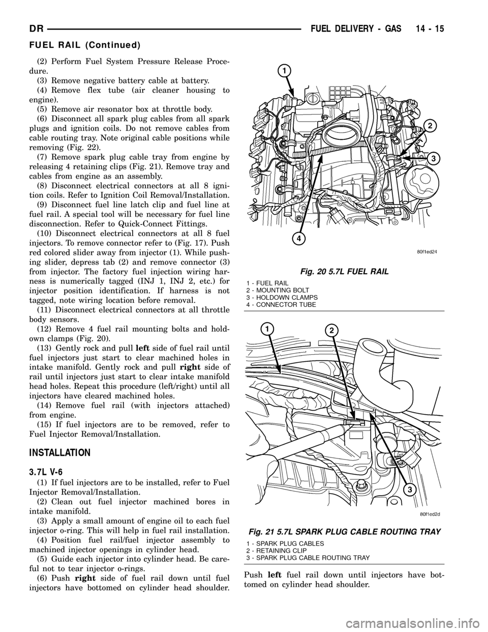
(2) Perform Fuel System Pressure Release Proce-
dure.
(3) Remove negative battery cable at battery.
(4) Remove flex tube (air cleaner housing to
engine).
(5) Remove air resonator box at throttle body.
(6) Disconnect all spark plug cables from all spark
plugs and ignition coils. Do not remove cables from
cable routing tray. Note original cable positions while
removing (Fig. 22).
(7) Remove spark plug cable tray from engine by
releasing 4 retaining clips (Fig. 21). Remove tray and
cables from engine as an assembly.
(8) Disconnect electrical connectors at all 8 igni-
tion coils. Refer to Ignition Coil Removal/Installation.
(9) Disconnect fuel line latch clip and fuel line at
fuel rail. A special tool will be necessary for fuel line
disconnection. Refer to Quick-Connect Fittings.
(10) Disconnect electrical connectors at all 8 fuel
injectors. To remove connector refer to (Fig. 17). Push
red colored slider away from injector (1). While push-
ing slider, depress tab (2) and remove connector (3)
from injector. The factory fuel injection wiring har-
ness is numerically tagged (INJ 1, INJ 2, etc.) for
injector position identification. If harness is not
tagged, note wiring location before removal.
(11) Disconnect electrical connectors at all throttle
body sensors.
(12) Remove 4 fuel rail mounting bolts and hold-
own clamps (Fig. 20).
(13) Gently rock and pullleftside of fuel rail until
fuel injectors just start to clear machined holes in
intake manifold. Gently rock and pullrightside of
rail until injectors just start to clear intake manifold
head holes. Repeat this procedure (left/right) until all
injectors have cleared machined holes.
(14) Remove fuel rail (with injectors attached)
from engine.
(15) If fuel injectors are to be removed, refer to
Fuel Injector Removal/Installation.
INSTALLATION
3.7L V-6
(1) If fuel injectors are to be installed, refer to Fuel
Injector Removal/Installation.
(2) Clean out fuel injector machined bores in
intake manifold.
(3) Apply a small amount of engine oil to each fuel
injector o-ring. This will help in fuel rail installation.
(4) Position fuel rail/fuel injector assembly to
machined injector openings in cylinder head.
(5) Guide each injector into cylinder head. Be care-
ful not to tear injector o-rings.
(6) Pushrightside of fuel rail down until fuel
injectors have bottomed on cylinder head shoulder.Pushleftfuel rail down until injectors have bot-
tomed on cylinder head shoulder.
Fig. 20 5.7L FUEL RAIL
1 - FUEL RAIL
2 - MOUNTING BOLT
3 - HOLDOWN CLAMPS
4 - CONNECTOR TUBE
Fig. 21 5.7L SPARK PLUG CABLE ROUTING TRAY
1 - SPARK PLUG CABLES
2 - RETAINING CLIP
3 - SPARK PLUG CABLE ROUTING TRAY
DRFUEL DELIVERY - GAS 14 - 15
FUEL RAIL (Continued)
Page 1591 of 2627
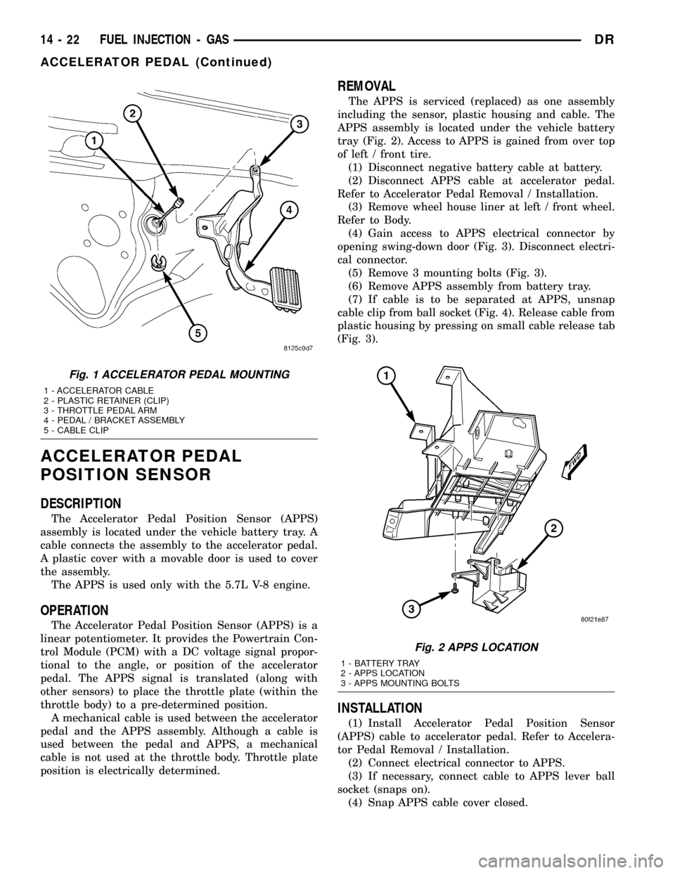
ACCELERATOR PEDAL
POSITION SENSOR
DESCRIPTION
The Accelerator Pedal Position Sensor (APPS)
assembly is located under the vehicle battery tray. A
cable connects the assembly to the accelerator pedal.
A plastic cover with a movable door is used to cover
the assembly.
The APPS is used only with the 5.7L V-8 engine.
OPERATION
The Accelerator Pedal Position Sensor (APPS) is a
linear potentiometer. It provides the Powertrain Con-
trol Module (PCM) with a DC voltage signal propor-
tional to the angle, or position of the accelerator
pedal. The APPS signal is translated (along with
other sensors) to place the throttle plate (within the
throttle body) to a pre-determined position.
A mechanical cable is used between the accelerator
pedal and the APPS assembly. Although a cable is
used between the pedal and APPS, a mechanical
cable is not used at the throttle body. Throttle plate
position is electrically determined.
REMOVAL
The APPS is serviced (replaced) as one assembly
including the sensor, plastic housing and cable. The
APPS assembly is located under the vehicle battery
tray (Fig. 2). Access to APPS is gained from over top
of left / front tire.
(1) Disconnect negative battery cable at battery.
(2) Disconnect APPS cable at accelerator pedal.
Refer to Accelerator Pedal Removal / Installation.
(3) Remove wheel house liner at left / front wheel.
Refer to Body.
(4) Gain access to APPS electrical connector by
opening swing-down door (Fig. 3). Disconnect electri-
cal connector.
(5) Remove 3 mounting bolts (Fig. 3).
(6) Remove APPS assembly from battery tray.
(7) If cable is to be separated at APPS, unsnap
cable clip from ball socket (Fig. 4). Release cable from
plastic housing by pressing on small cable release tab
(Fig. 3).
INSTALLATION
(1) Install Accelerator Pedal Position Sensor
(APPS) cable to accelerator pedal. Refer to Accelera-
tor Pedal Removal / Installation.
(2) Connect electrical connector to APPS.
(3) If necessary, connect cable to APPS lever ball
socket (snaps on).
(4) Snap APPS cable cover closed.
Fig. 1 ACCELERATOR PEDAL MOUNTING
1 - ACCELERATOR CABLE
2 - PLASTIC RETAINER (CLIP)
3 - THROTTLE PEDAL ARM
4 - PEDAL / BRACKET ASSEMBLY
5 - CABLE CLIP
Fig. 2 APPS LOCATION
1 - BATTERY TRAY
2 - APPS LOCATION
3 - APPS MOUNTING BOLTS
14 - 22 FUEL INJECTION - GASDR
ACCELERATOR PEDAL (Continued)
Page 1596 of 2627
stream. The spraying action atomizes the fuel, add-
ing it to the air entering the combustion chamber.
The nozzle (outlet) ends of the injectors are posi-
tioned into openings in the intake manifold just
above the intake valve ports of the cylinder head.
The engine wiring harness connector for each fuel
injector is equipped with an attached numerical tag
(INJ 1, INJ 2 etc.). This is used to identify each fuel
injector.
The injectors are energized individually in a
sequential order by the Powertrain Control Module
(PCM). The PCM will adjust injector pulse width by
switching the ground path to each individual injector
on and off. Injector pulse width is the period of time
that the injector is energized. The PCM will adjust
injector pulse width based on various inputs it
receives.
Battery voltage is supplied to the injectors through
the ASD relay.
The PCM determines injector pulse width based on
various inputs.
OPERATION - PCM OUTPUT
The nozzle ends of the injectors are positioned into
openings in the intake manifold just above the intake
valve ports of the cylinder head. The engine wiring
harness connector for each fuel injector is equipped
with an attached numerical tag (INJ 1, INJ 2 etc.).
This is used to identify each fuel injector with its
respective cylinder number.
The injectors are energized individually in a
sequential order by the Powertrain Control Module
(PCM). The PCM will adjust injector pulse width by
switching the ground path to each individual injector
on and off. Injector pulse width is the period of time
that the injector is energized. The PCM will adjust
injector pulse width based on various inputs it
receives.
Battery voltage (12 volts +) is supplied to the injec-
tors through the ASD relay. The ASD relay will shut-
down the 12 volt power source to the fuel injectors if
the PCM senses the ignition is on, but the engine is
not running. This occurs after the engine has not
been running for approximately 1.8 seconds.
The PCM determines injector on-time (pulse width)
based on various inputs.
REMOVAL
(1) Remove fuel rail. Refer to Fuel Injector Rail
Removal.
(2) Disconnect clip(s) that retain fuel injector(s) to
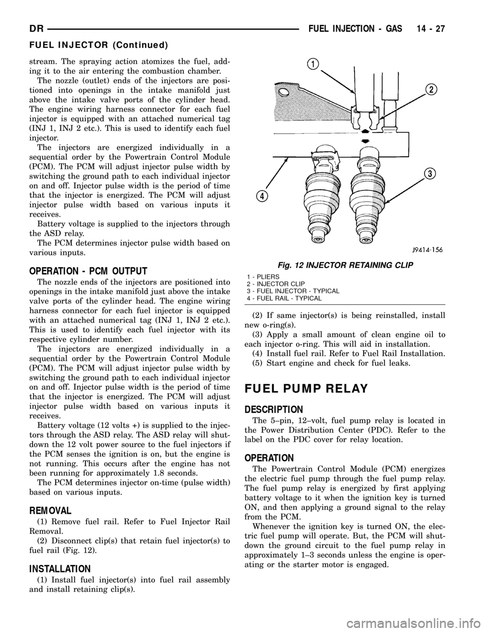
fuel rail (Fig. 12).
INSTALLATION
(1) Install fuel injector(s) into fuel rail assembly
and install retaining clip(s).(2) If same injector(s) is being reinstalled, install
new o-ring(s).
(3) Apply a small amount of clean engine oil to
each injector o-ring. This will aid in installation.
(4) Install fuel rail. Refer to Fuel Rail Installation.
(5) Start engine and check for fuel leaks.
FUEL PUMP RELAY
DESCRIPTION
The 5±pin, 12±volt, fuel pump relay is located in
the Power Distribution Center (PDC). Refer to the
label on the PDC cover for relay location.
OPERATION
The Powertrain Control Module (PCM) energizes
the electric fuel pump through the fuel pump relay.
The fuel pump relay is energized by first applying
battery voltage to it when the ignition key is turned
ON, and then applying a ground signal to the relay
from the PCM.
Whenever the ignition key is turned ON, the elec-
tric fuel pump will operate. But, the PCM will shut-
down the ground circuit to the fuel pump relay in
approximately 1±3 seconds unless the engine is oper-
ating or the starter motor is engaged.
Fig. 12 INJECTOR RETAINING CLIP
1 - PLIERS
2 - INJECTOR CLIP
3 - FUEL INJECTOR - TYPICAL
4 - FUEL RAIL - TYPICAL
DRFUEL INJECTION - GAS 14 - 27
FUEL INJECTOR (Continued)
Page 1597 of 2627
REMOVAL
The fuel pump relay is located in the Power Distri-
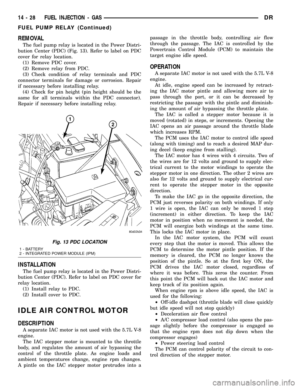
bution Center (PDC) (Fig. 13). Refer to label on PDC
cover for relay location.
(1) Remove PDC cover.
(2) Remove relay from PDC.
(3) Check condition of relay terminals and PDC
connector terminals for damage or corrosion. Repair
if necessary before installing relay.
(4) Check for pin height (pin height should be the
same for all terminals within the PDC connector).
Repair if necessary before installing relay.
INSTALLATION
The fuel pump relay is located in the Power Distri-
bution Center (PDC). Refer to label on PDC cover for
relay location.
(1) Install relay to PDC.
(2) Install cover to PDC.
IDLE AIR CONTROL MOTOR
DESCRIPTION
A separate IAC motor is not used with the 5.7L V-8
engine.
The IAC stepper motor is mounted to the throttle
body, and regulates the amount of air bypassing the
control of the throttle plate. As engine loads and
ambient temperatures change, engine rpm changes.
A pintle on the IAC stepper motor protrudes into apassage in the throttle body, controlling air flow
through the passage. The IAC is controlled by the
Powertrain Control Module (PCM) to maintain the
target engine idle speed.
OPERATION
A separate IAC motor is not used with the 5.7L V-8
engine.
At idle, engine speed can be increased by retract-
ing the IAC motor pintle and allowing more air to
pass through the port, or it can be decreased by
restricting the passage with the pintle and diminish-
ing the amount of air bypassing the throttle plate.
The IAC is called a stepper motor because it is
moved (rotated) in steps, or increments. Opening the
IAC opens an air passage around the throttle blade
which increases RPM.
The PCM uses the IAC motor to control idle speed
(along with timing) and to reach a desired MAP dur-
ing decel (keep engine from stalling).
The IAC motor has 4 wires with 4 circuits. Two of
the wires are for 12 volts and ground to supply elec-
trical current to the motor windings to operate the
stepper motor in one direction. The other 2 wires are
also for 12 volts and ground to supply electrical cur-
rent to operate the stepper motor in the opposite
direction.
To make the IAC go in the opposite direction, the
PCM just reverses polarity on both windings. If only
1 wire is open, the IAC can only be moved 1 step
(increment) in either direction. To keep the IAC
motor in position when no movement is needed, the
PCM will energize both windings at the same time.
This locks the IAC motor in place.
In the IAC motor system, the PCM will count
every step that the motor is moved. This allows the
PCM to determine the motor pintle position. If the
memory is cleared, the PCM no longer knows the
position of the pintle. So at the first key ON, the
PCM drives the IAC motor closed, regardless of
where it was before. This zeros the counter. From
this point the PCM will back out the IAC motor and
keep track of its position again.
When engine rpm is above idle speed, the IAC is
used for the following:
²Off-idle dashpot (throttle blade will close quickly
but idle speed will not stop quickly)
²Deceleration air flow control
²A/C compressor load control (also opens the pas-
sage slightly before the compressor is engaged so
that the engine rpm does not dip down when the
compressor engages)
²Power steering load control
The PCM can control polarity of the circuit to con-
trol direction of the stepper motor.
Fig. 13 PDC LOCATION
1 - BATTERY
2 - INTEGRATED POWER MODULE (IPM)
14 - 28 FUEL INJECTION - GASDR
FUEL PUMP RELAY (Continued)