Gauge DODGE RAM 1500 1998 2.G Workshop Manual
[x] Cancel search | Manufacturer: DODGE, Model Year: 1998, Model line: RAM 1500, Model: DODGE RAM 1500 1998 2.GPages: 2627
Page 1471 of 2627
ENGINE DATA PLATE
DESCRIPTION
The engine data plate contains specific information
that is helpful to servicing and obtaining parts for
the engine. The data plate can be found affixed to the
breather cover on the left side of the engine. Informa-
tion that can be found on the data plate includes:
²Date of Engine Manufacture
²Engine Serial Number
²Control Parts List (CPL)
²Engine Rated Horsepower
²Engine Firing Order
²Engine Displacement
²Valve Lash Reset Specifications
If the engine data plate is missing or not legible,
the engine serial number is used for engine identifi-
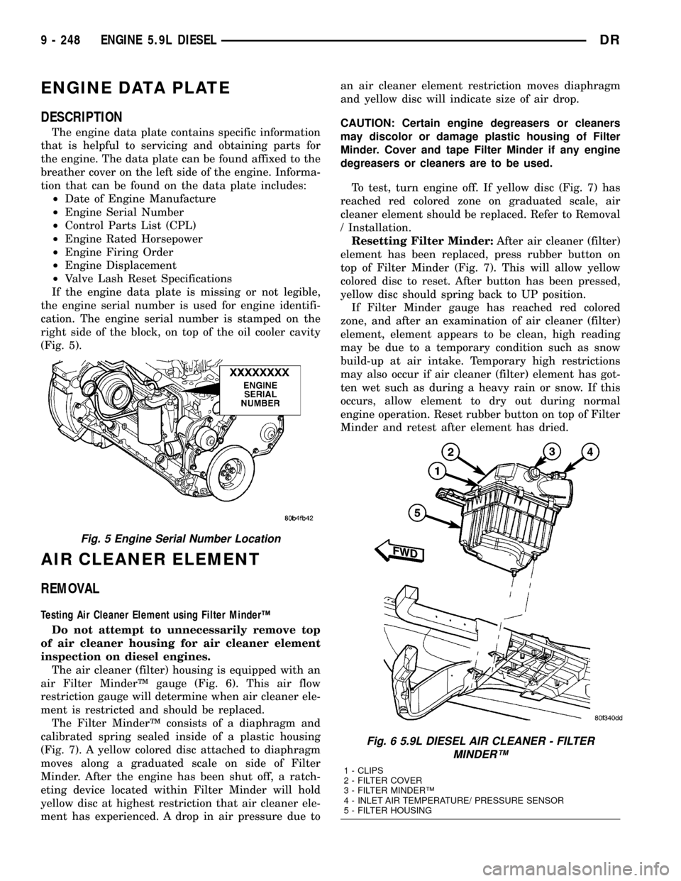
cation. The engine serial number is stamped on the
right side of the block, on top of the oil cooler cavity
(Fig. 5).
AIR CLEANER ELEMENT
REMOVAL
Testing Air Cleaner Element using Filter MinderŸ
Do not attempt to unnecessarily remove top
of air cleaner housing for air cleaner element
inspection on diesel engines.
The air cleaner (filter) housing is equipped with an
air Filter MinderŸ gauge (Fig. 6). This air flow
restriction gauge will determine when air cleaner ele-
ment is restricted and should be replaced.
The Filter MinderŸ consists of a diaphragm and
calibrated spring sealed inside of a plastic housing
(Fig. 7). A yellow colored disc attached to diaphragm
moves along a graduated scale on side of Filter
Minder. After the engine has been shut off, a ratch-
eting device located within Filter Minder will hold
yellow disc at highest restriction that air cleaner ele-
ment has experienced. A drop in air pressure due toan air cleaner element restriction moves diaphragm
and yellow disc will indicate size of air drop.
CAUTION: Certain engine degreasers or cleaners
may discolor or damage plastic housing of Filter
Minder. Cover and tape Filter Minder if any engine
degreasers or cleaners are to be used.
To test, turn engine off. If yellow disc (Fig. 7) has
reached red colored zone on graduated scale, air
cleaner element should be replaced. Refer to Removal
/ Installation.
Resetting Filter Minder:After air cleaner (filter)
element has been replaced, press rubber button on
top of Filter Minder (Fig. 7). This will allow yellow
colored disc to reset. After button has been pressed,
yellow disc should spring back to UP position.
If Filter Minder gauge has reached red colored
zone, and after an examination of air cleaner (filter)
element, element appears to be clean, high reading
may be due to a temporary condition such as snow
build-up at air intake. Temporary high restrictions
may also occur if air cleaner (filter) element has got-
ten wet such as during a heavy rain or snow. If this
occurs, allow element to dry out during normal
engine operation. Reset rubber button on top of Filter
Minder and retest after element has dried.
Fig. 5 Engine Serial Number Location
Fig. 6 5.9L DIESEL AIR CLEANER - FILTER
MINDERŸ
1 - CLIPS
2 - FILTER COVER
3 - FILTER MINDERŸ
4 - INLET AIR TEMPERATURE/ PRESSURE SENSOR
5 - FILTER HOUSING
9 - 248 ENGINE 5.9L DIESELDR
Page 1475 of 2627
CLEANINGÐPUSHRODS
Clean the pushrods in a suitable solvent. Rinse in
hot water and blow dry with compressed air. If nec-
essary, use a wire brush or wheel to remove stubborn
deposits.
INSPECTION
INSPECTION - CYLINDER HEAD
Inspect the cylinder head for cracks in the combus-
tion surface. Pressure test any cylinder head that is
visibly cracked. A cylinder head that is cracked
between the injector bore and valve seat can be pres-
sure tested and reused if OK; however, if the crack
extendsintothe valve seat insert bore, the cylinder
headmustbe replaced.
Visually inspect the cylinder block and head com-
bustion surfaces for localized dips or imperfections.
Check the cylinder head and block combustion sur-
faces for overall out-of-flatness. If either the visual or
manual inspection exceeds the limits, then the head
or block must be surfaced.
Check the top surface for damage caused by the
cylinder head gasket leaking between cylinders.
Inspect the block and head surface for nicks, ero-
sion, etc.
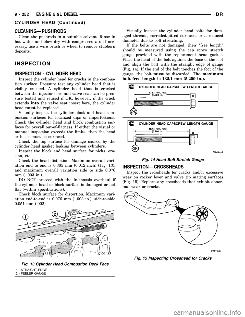
Check the head distortion. Maximum overall vari-
ation end to end is 0.305 mm (0.012 inch) (Fig. 13),
and maximum overall variation side to side 0.076
mm ( .003 in.).
DO NOT proceed with the in-chassis overhaul if
the cylinder head or block surface is damaged or not
flat (within specifications).
Check block surface for distortion. Maximum vari-
ation end-to-end is 0.076 mm ( .003 in.), side-to-side
0.051 mm (.002).Visually inspect the cylinder head bolts for dam-
aged threads, corroded/pitted surfaces, or a reduced
diameter due to bolt stretching.
If the bolts are not damaged, their ªfree lengthº
should be measured using the cap screw stretch
gauge provided with the replacement head gasket.
Place the head of the bolt against the base of the slot
and align the bolt with the straight edge of gauge
(Fig. 14). If the end of the bolt touches the foot of the
gauge, the boltmustbe discarded.The maximum
bolt free length is 132.1 mm (5.200 in.).
INSPECTIONÐCROSSHEADS
Inspect the crossheads for cracks and/or excessive
wear on rocker lever and valve tip mating surfaces
(Fig. 15). Replace any crossheads that exhibit abnor-
mal wear or cracks.
Fig. 13 Cylinder Head Combustion Deck Face
1 - STRAIGHT EDGE
2 - FEELER GAUGE
Fig. 14 Head Bolt Stretch Gauge
Fig. 15 Inspecting Crosshead for Cracks
9 - 252 ENGINE 5.9L DIESELDR
CYLINDER HEAD (Continued)
Page 1482 of 2627
INSTALLATION
(1) Install new valve seals. The yellow seals are for
the intake valves and the green seals are for the
exhaust valves.
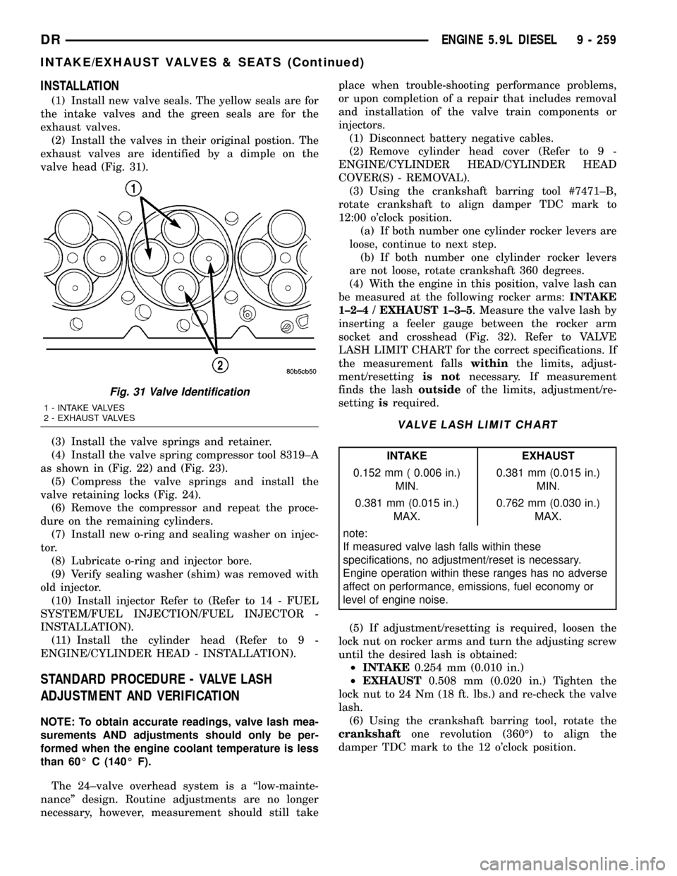
(2) Install the valves in their original postion. The
exhaust valves are identified by a dimple on the
valve head (Fig. 31).
(3) Install the valve springs and retainer.
(4) Install the valve spring compressor tool 8319±A
as shown in (Fig. 22) and (Fig. 23).
(5) Compress the valve springs and install the
valve retaining locks (Fig. 24).
(6) Remove the compressor and repeat the proce-
dure on the remaining cylinders.
(7) Install new o-ring and sealing washer on injec-
tor.
(8) Lubricate o-ring and injector bore.
(9) Verify sealing washer (shim) was removed with
old injector.
(10) Install injector Refer to (Refer to 14 - FUEL
SYSTEM/FUEL INJECTION/FUEL INJECTOR -
INSTALLATION).
(11) Install the cylinder head (Refer to 9 -
ENGINE/CYLINDER HEAD - INSTALLATION).
STANDARD PROCEDURE - VALVE LASH
ADJUSTMENT AND VERIFICATION
NOTE: To obtain accurate readings, valve lash mea-
surements AND adjustments should only be per-
formed when the engine coolant temperature is less
than 60É C (140É F).
The 24±valve overhead system is a ªlow-mainte-
nanceº design. Routine adjustments are no longer
necessary, however, measurement should still takeplace when trouble-shooting performance problems,
or upon completion of a repair that includes removal
and installation of the valve train components or
injectors.
(1) Disconnect battery negative cables.
(2) Remove cylinder head cover (Refer to 9 -
ENGINE/CYLINDER HEAD/CYLINDER HEAD
COVER(S) - REMOVAL).
(3) Using the crankshaft barring tool #7471±B,
rotate crankshaft to align damper TDC mark to
12:00 o'clock position.
(a) If both number one cylinder rocker levers are
loose, continue to next step.
(b) If both number one clylinder rocker levers
are not loose, rotate crankshaft 360 degrees.
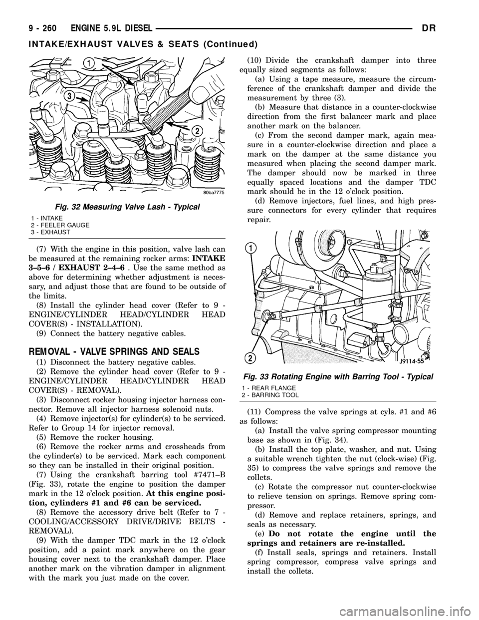
(4) With the engine in this position, valve lash can
be measured at the following rocker arms:INTAKE
1±2±4 / EXHAUST 1±3±5. Measure the valve lash by
inserting a feeler gauge between the rocker arm
socket and crosshead (Fig. 32). Refer to VALVE
LASH LIMIT CHART for the correct specifications. If
the measurement fallswithinthe limits, adjust-
ment/resettingis notnecessary. If measurement
finds the lashoutsideof the limits, adjustment/re-
settingisrequired.
VALVE LASH LIMIT CHART
INTAKE EXHAUST
0.152 mm ( 0.006 in.)
MIN.0.381 mm (0.015 in.)
MIN.
0.381 mm (0.015 in.)
MAX.0.762 mm (0.030 in.)
MAX.
note:
If measured valve lash falls within these
specifications, no adjustment/reset is necessary.
Engine operation within these ranges has no adverse
affect on performance, emissions, fuel economy or
level of engine noise.
(5) If adjustment/resetting is required, loosen the
lock nut on rocker arms and turn the adjusting screw
until the desired lash is obtained:
²INTAKE0.254 mm (0.010 in.)
²EXHAUST0.508 mm (0.020 in.) Tighten the
lock nut to 24 Nm (18 ft. lbs.) and re-check the valve
lash.
(6) Using the crankshaft barring tool, rotate the
crankshaftone revolution (360É) to align the
damper TDC mark to the 12 o'clock position.
Fig. 31 Valve Identification
1 - INTAKE VALVES
2 - EXHAUST VALVES
DRENGINE 5.9L DIESEL 9 - 259
INTAKE/EXHAUST VALVES & SEATS (Continued)
Page 1483 of 2627
(7) With the engine in this position, valve lash can
be measured at the remaining rocker arms:INTAKE
3±5±6 / EXHAUST 2±4±6. Use the same method as
above for determining whether adjustment is neces-
sary, and adjust those that are found to be outside of
the limits.
(8) Install the cylinder head cover (Refer to 9 -
ENGINE/CYLINDER HEAD/CYLINDER HEAD
COVER(S) - INSTALLATION).
(9) Connect the battery negative cables.
REMOVAL - VALVE SPRINGS AND SEALS
(1) Disconnect the battery negative cables.
(2) Remove the cylinder head cover (Refer to 9 -
ENGINE/CYLINDER HEAD/CYLINDER HEAD
COVER(S) - REMOVAL).
(3) Disconnect rocker housing injector harness con-
nector. Remove all injector harness solenoid nuts.
(4) Remove injector(s) for cylinder(s) to be serviced.
Refer to Group 14 for injector removal.
(5) Remove the rocker housing.
(6) Remove the rocker arms and crossheads from
the cylinder(s) to be serviced. Mark each component
so they can be installed in their original position.
(7) Using the crankshaft barring tool #7471±B
(Fig. 33), rotate the engine to position the damper
mark in the 12 o'clock position.At this engine posi-
tion, cylinders #1 and #6 can be serviced.
(8) Remove the accessory drive belt (Refer to 7 -
COOLING/ACCESSORY DRIVE/DRIVE BELTS -
REMOVAL).
(9) With the damper TDC mark in the 12 o'clock
position, add a paint mark anywhere on the gear
housing cover next to the crankshaft damper. Place
another mark on the vibration damper in alignment
with the mark you just made on the cover.(10) Divide the crankshaft damper into three
equally sized segments as follows:
(a) Using a tape measure, measure the circum-
ference of the crankshaft damper and divide the
measurement by three (3).
(b) Measure that distance in a counter-clockwise
direction from the first balancer mark and place
another mark on the balancer.
(c) From the second damper mark, again mea-
sure in a counter-clockwise direction and place a
mark on the damper at the same distance you
measured when placing the second damper mark.
The damper should now be marked in three
equally spaced locations and the damper TDC
mark should be in the 12 o'clock position.
(d) Remove injectors, fuel lines, and high pres-
sure connectors for every cylinder that requires
repair.
(11) Compress the valve springs at cyls. #1 and #6
as follows:
(a) Install the valve spring compressor mounting
base as shown in (Fig. 34).
(b) Install the top plate, washer, and nut. Using
a suitable wrench tighten the nut (clock-wise) (Fig.
35) to compress the valve springs and remove the
collets.
(c) Rotate the compressor nut counter-clockwise
to relieve tension on springs. Remove spring com-
pressor.
(d) Remove and replace retainers, springs, and
seals as necessary.
(e)Do not rotate the engine until the
springs and retainers are re-installed.
(f) Install seals, springs and retainers. Install
spring compressor, compress valve springs and
install the collets.
Fig. 32 Measuring Valve Lash - Typical
1 - INTAKE
2 - FEELER GAUGE
3 - EXHAUST
Fig. 33 Rotating Engine with Barring Tool - Typical
1 - REAR FLANGE
2 - BARRING TOOL
9 - 260 ENGINE 5.9L DIESELDR
INTAKE/EXHAUST VALVES & SEATS (Continued)
Page 1490 of 2627
After removing the boring bar, use a honing stone
to chamfer the corner of the repair sleeve(s).
SLEEVE MACHINING DIMENSIONS CHART
ITEM MEASUREMENT
SLEEVE PROTRUSION MIN. - FLUSH WITH
BLOCK
MAX. - 0.050 mm
(0.0019 in.)
SLEEVE DIAMETER 101.956 mm (4.014 in.)
SLEEVE CHAMFER APPROX. 1.25 mm
(0.049 in.) by 15É
A correctly honed surface will have a crosshatch
appearance with the lines at 15É to 25É angles with
the top of the cylinder block. For the rough hone, use
80 grit honing stones. To finish hone, use 280 grit
honing stones.
Finished bore inside dimension is 102.020 0.020
mm (4.0165 0.0008 inch).
A maximum of 1.2 micrometer (48 microinch) sur-
face finish must be obtained.
After finish honing is complete, immediately clean
the cylinder bores with a strong solution of laundry
detergent and hot water.
After rinsing, blow the block dry with compressed
air.
Wipe the bore with a white, lint-free, lightly oiled
cloth. Make sure there is no grit residue present.
Apply a rust-preventing compound if the block will
not be used immediately.
A standard diameter piston and a piston ring set
must be used with a sleeved cylinder bore.
STANDARD PROCEDUREÐCAM BORE REPAIR
For standard bushings, not oversized, maximum
front and rear cam bushing bore diameter is 59.248
mm. (2.3326 in.). DO NOT bore the intermediate cam
bore to the front cam bore oversize dimensions. Max-
imum front and rear camshaft bushing installed
diameter is 54.147 mm. (2.1318 in.). Minimum
installed diameter is 54.083 mm. (2.1293 in.). Maxi-
mum intermediate camshaft bore diameter is 54.164
mm. (2.1324 in.).
A surface finish of 2.3 micrometers (92 microinch)
must be maintained. Not more than 20% of an area
of any one bore may be 3.2 micrometers (126 micro-
inch).
Camshaft bores can be repaired individually. It is
not necessary to repair undamaged cam bores in
order to repair individually damaged cam bores. The
standard front bushing cannot be used to repair
intermediate bores.Install all cam bushings flush or below the front
and rear cam bore surface. The front camshaft bush-
ing should be installed flush with front face of block.
The rear camshaft bushing should be installed flush
with rear face of block. The oil hole must align to
allow a 3.2 mm (0.125 inch) rod to pass through
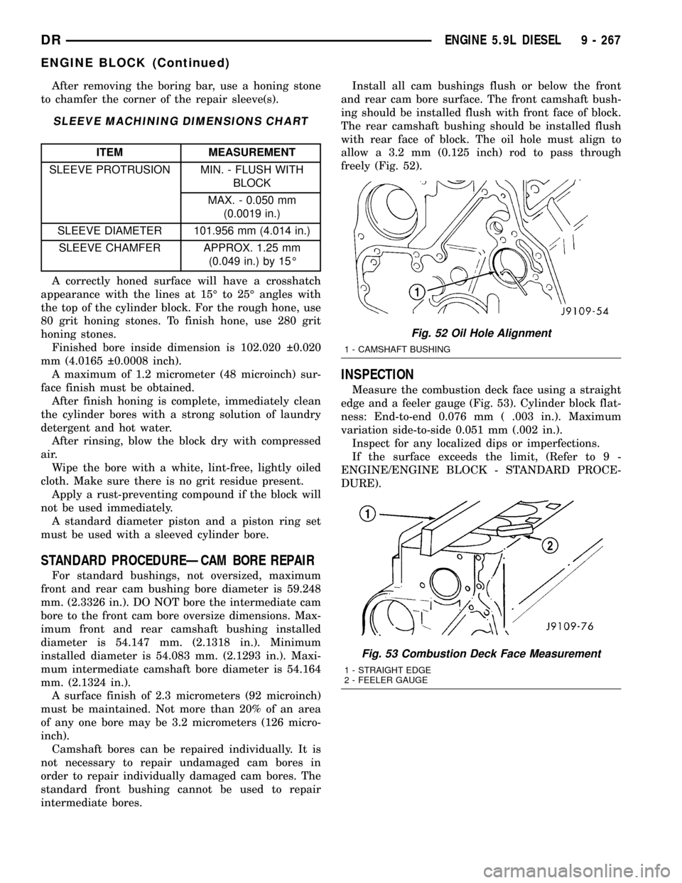
freely (Fig. 52).
INSPECTION
Measure the combustion deck face using a straight
edge and a feeler gauge (Fig. 53). Cylinder block flat-
ness: End-to-end 0.076 mm ( .003 in.). Maximum
variation side-to-side 0.051 mm (.002 in.).
Inspect for any localized dips or imperfections.
If the surface exceeds the limit, (Refer to 9 -
ENGINE/ENGINE BLOCK - STANDARD PROCE-
DURE).
Fig. 52 Oil Hole Alignment
1 - CAMSHAFT BUSHING
Fig. 53 Combustion Deck Face Measurement
1 - STRAIGHT EDGE
2 - FEELER GAUGE
DRENGINE 5.9L DIESEL 9 - 267
ENGINE BLOCK (Continued)
Page 1493 of 2627
INSPECTION
Camshaft
(1) Inspect the valve lobes and bearing journals for
cracks, pitting, scoring, or generally excessive wear.
Replace any camshaft that exceeds the allowable lim-
its.
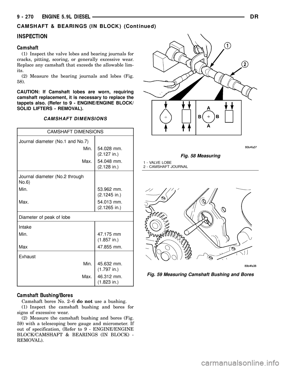
(2) Measure the bearing journals and lobes (Fig.
58).
CAUTION: If Camshaft lobes are worn, requiring
camshaft replacement, it is necessary to replace the
tappets also. (Refer to 9 - ENGINE/ENGINE BLOCK/
SOLID LIFTERS - REMOVAL).
CAMSHAFT DIMENSIONS
CAMSHAFT DIMENSIONS
Journal diameter (No.1 and No.7)
Min. 54.028 mm.
(2.127 in.)
Max. 54.048 mm.
(2.128 in.)
Journal diameter (No.2 through
No.6)
Min. 53.962 mm.
(2.1245 in.)
Max. 54.013 mm.
(2.1265 in.)
Diameter of peak of lobe
Intake
Min. 47.175 mm
(1.857 in.)
Max 47.855 mm.
Exhaust
Min. 45.632 mm.
(1.797 in.)
Max. 46.312 mm.
(1.823 in.)
Camshaft Bushing/Bores
Camshaft bores No. 2±6do notuse a bushing.
(1) Inspect the camshaft bushing and bores for
signs of excessive wear.
(2) Measure the camshaft bushing and bores (Fig.
59) with a telescoping bore gauge and micrometer. If
out of specification, (Refer to 9 - ENGINE/ENGINE
BLOCK/CAMSHAFT & BEARINGS (IN BLOCK) -
REMOVAL).
Fig. 59 Measuring Camshaft Bushing and Bores
Fig. 58 Measuring
1 - VALVE LOBE
2 - CAMSHAFT JOURNAL
9 - 270 ENGINE 5.9L DIESELDR
CAMSHAFT & BEARINGS (IN BLOCK) (Continued)
Page 1500 of 2627
(7) Install the flywheel or converter drive plate.
Tighten the bolts to 137 N´m (101 ft. lbs.) torque.
(8) Install the clutch cover and disc (if equipped)
(Refer to 6 - CLUTCH/CLUTCH DISC - INSTALLA-
TION).
(9) Install the transmission and transfer case (if
equipped).
(10) Lower vehicle.
(11) Connect battery negative cables.
(12) Check engine oil level and adjust, if necessary.
(13) Start engine and check for oil leaks.
CRANKSHAFT REAR OIL SEAL
RETAINER
REMOVAL
(1) Disconnect the battery negative cables.
(2) Raise vehicle on hoist.
(3) Remove the oil pan drain plug and drain the
engine oil. Re-install plug and torque to 50 N´m (44
ft. lbs.) torque.
(4) Remove transmission and transfer case (if
equipped) from vehicle.
(5)
Remove flywheel or torque converter drive plate.
(6) Disconnect starter cables from starter motor.
(7) Remove starter motor (Refer to 8 - ELECTRI-
CAL/STARTING/STARTER MOTOR - REMOVAL)
and transmission adapter plate assembly.
(8) Remove four (4) oil pan rear bolts. Slide a
feeler gauge between the seal retainer and oil pan
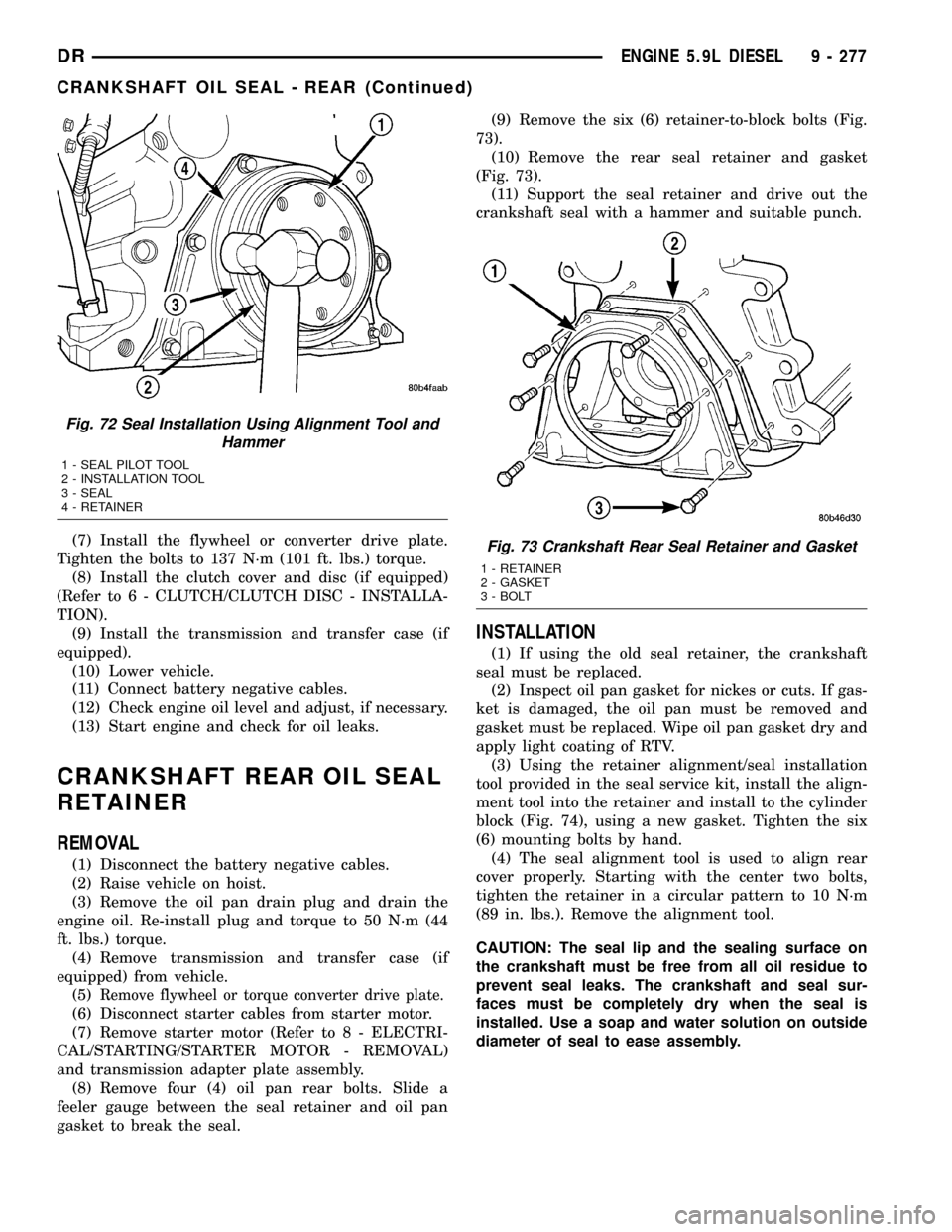
gasket to break the seal.(9) Remove the six (6) retainer-to-block bolts (Fig.
73).
(10) Remove the rear seal retainer and gasket
(Fig. 73).
(11) Support the seal retainer and drive out the
crankshaft seal with a hammer and suitable punch.
INSTALLATION
(1) If using the old seal retainer, the crankshaft
seal must be replaced.
(2) Inspect oil pan gasket for nickes or cuts. If gas-
ket is damaged, the oil pan must be removed and
gasket must be replaced. Wipe oil pan gasket dry and
apply light coating of RTV.
(3) Using the retainer alignment/seal installation
tool provided in the seal service kit, install the align-
ment tool into the retainer and install to the cylinder
block (Fig. 74), using a new gasket. Tighten the six
(6) mounting bolts by hand.
(4) The seal alignment tool is used to align rear
cover properly. Starting with the center two bolts,
tighten the retainer in a circular pattern to 10 N´m
(89 in. lbs.). Remove the alignment tool.
CAUTION: The seal lip and the sealing surface on
the crankshaft must be free from all oil residue to
prevent seal leaks. The crankshaft and seal sur-
faces must be completely dry when the seal is
installed. Use a soap and water solution on outside
diameter of seal to ease assembly.
Fig. 72 Seal Installation Using Alignment Tool and
Hammer
1 - SEAL PILOT TOOL
2 - INSTALLATION TOOL
3 - SEAL
4 - RETAINER
Fig. 73 Crankshaft Rear Seal Retainer and Gasket
1 - RETAINER
2 - GASKET
3 - BOLT
DRENGINE 5.9L DIESEL 9 - 277
CRANKSHAFT OIL SEAL - REAR (Continued)
Page 1505 of 2627
NOTE: If cylinders have ridges, the cylinders are
oversize and will more than likely need boring.
(8) Using a hammer and steel stamp, stamp the
cylinder number in the top of each piston. The front
of the piston is identified by a stamping on the top of
the piston. DO NOT stamp in the outside 5 mm (.197
in.) of the piston diameter. DO NOT stamp over the
piston pin.
(9) Mark the connecting rod and cap with the cor-
responding cylinder numbers.
(10) Remove the connecting rod bolts and rod caps.
Use care so the cylinder bores and connecting rods
are not damaged.
(11) Use a hammer handle or similar object to
push the piston and connecting rod through the cyl-
inder bore.
(12) Store the piston/rod assemblies in a rack.
CLEANINGÐPISTON AND CONNECTING ROD
CAUTION: DO NOT use bead blast to clean the pis-
tons. DO NOT clean the pistons and rods in an acid
tank.
PISTON
Clean the pistons and pins in a suitable solvent,
rinse in hot water and blow dry with compressed air.
Soaking the pistons over night will loosen most of the
carbon build up. De-carbon the ring grooves with a
broken piston ring and again clean the pistons in sol-
vent. Rinse in hot water and blow dry with com-
pressed air.
CONNECTING ROD
Clean the connecting rods in a suitable solvent,
rinse in hot water and blow dry with compressed air.
INSPECTION
INSPECTION - PISTONS
Inspect the pistons for damage and excessive wear.
Check top of the piston, ring grooves, skirt and pin
bore. Measure the piston skirt diameter. If the piston
is out of limits, replace the piston.
PISTON SKIRT DIAMETER (MIN.)
101.775 mm (4.006 in. )The upper groove only needs to be inspected for
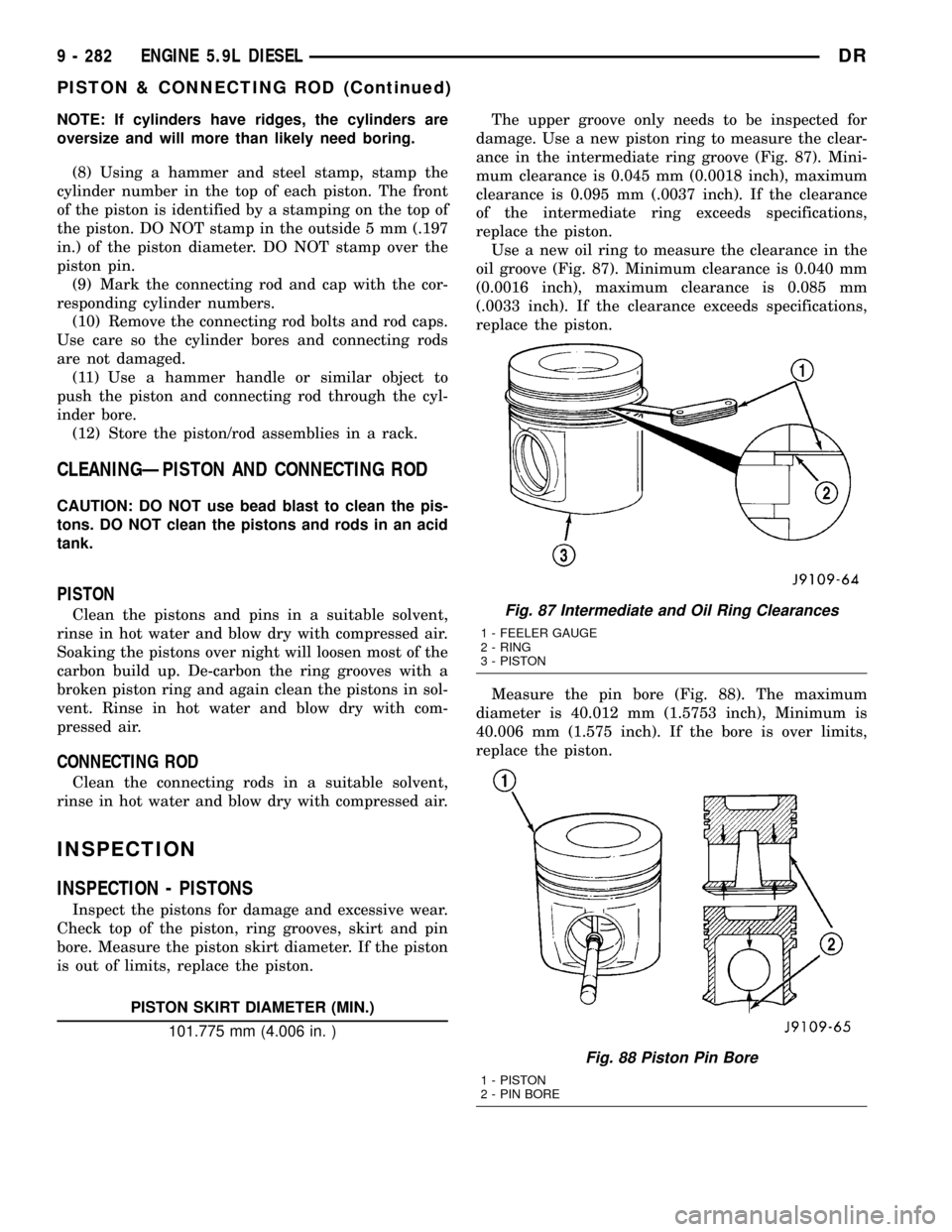
damage. Use a new piston ring to measure the clear-
ance in the intermediate ring groove (Fig. 87). Mini-
mum clearance is 0.045 mm (0.0018 inch), maximum
clearance is 0.095 mm (.0037 inch). If the clearance
of the intermediate ring exceeds specifications,
replace the piston.
Use a new oil ring to measure the clearance in the
oil groove (Fig. 87). Minimum clearance is 0.040 mm
(0.0016 inch), maximum clearance is 0.085 mm
(.0033 inch). If the clearance exceeds specifications,
replace the piston.
Measure the pin bore (Fig. 88). The maximum
diameter is 40.012 mm (1.5753 inch), Minimum is
40.006 mm (1.575 inch). If the bore is over limits,
replace the piston.
Fig. 87 Intermediate and Oil Ring Clearances
1 - FEELER GAUGE
2 - RING
3 - PISTON
Fig. 88 Piston Pin Bore
1 - PISTON
2 - PIN BORE
9 - 282 ENGINE 5.9L DIESELDR
PISTON & CONNECTING ROD (Continued)
Page 1507 of 2627
(10)For fractured/split type connecting rods,
the long end of the rod must be installed towards the
intake side of the engine.
(a) The connecting rod split/face must face
toward the same side as the piston notch feature
on the skirt. The split face will face toward the
exhaust side of the engine if properly installed.
(11) Install the rod cap and bolts to the connecting
rod. Tighten the connecting rod bolts evenly in 3
steps.
²Tighten the bolts to 30 N´m (22 ft. lbs.) torque.
²Tighten the bolts to 60 N´m (44 ft. lbs.) torque.
²Rotate 60É clockwise.
(12) The crankshaft must rotate freely. Check for
freedom of rotation as the caps are installed. If the
crankshaft does not rotate freely, check the installa-
tion of the rod bearing and the bearing size.
(13) Measure the side clearance between the con-
necting rod and the crankshaft. DO NOT measure
the clearance between the cap and crankshaft.
(14) Install J-jet piston cooling nozzles if equipped.
(15) Install block stiffener. Torque to 43 N´m (32 ft.
lbs.).
(16) Install the suction tube and oil pan (Refer to 9
- ENGINE/LUBRICATION/OIL PAN - INSTALLA-
TION).
(17) Install the cylinder head onto the engine
(Refer to 9 - ENGINE/CYLINDER HEAD - INSTAL-
LATION).
(18) Install a new filter and fill the crankcase with
new engine oil.Prefill the filter with clean oil.
(19) Connect the battery negative cables and start
engine.
PISTON RINGS
STANDARD PROCEDURE - PISTON RING
FITTING
(1) Determine the piston diameter and obtain the
appropriate ring set. The piston rings can be identi-
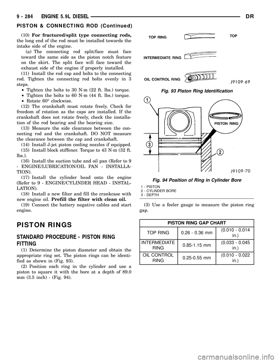
fied as shown in (Fig. 93).
(2) Position each ring in the cylinder and use a
piston to square it with the bore at a depth of 89.0
mm (3.5 inch) - (Fig. 94).(3) Use a feeler gauge to measure the piston ring
gap.
PISTON RING GAP CHART
TOP RING 0.26 - 0.36 mm(0.010 - 0.014
in.)
INTERMEDIATE
RING0.85-1.15 mm(0.033 - 0.045
in.)
OIL CONTROL
RING0.25-0.55 mm(0.010 - 0.022
in.)
Fig. 93 Piston Ring Identification
Fig. 94 Position of Ring in Cylinder Bore
1 - PISTON
2 - CYLINDER BORE
3 - DEPTH
9 - 284 ENGINE 5.9L DIESELDR
PISTON & CONNECTING ROD (Continued)
Page 1512 of 2627
LUBRICATION
DESCRIPTION
NOTE: Refer to (Fig. 105) and (Fig. 106) for circuit
illustrations.
A gear driven gerotor type oil pump is mounted
behind the front gear cover in the lower right portion
on the engine.
OPERATION
A gerotor style oil pump draws oil from the crank-
case through the suction tube and delivers it through
the block where it enters the oil cooler cover and
pressure regulator valve. When oil pressure exceeds
517 kPa (75 PSI), the valve opens exposing the dump
port, which routes excess oil back to the oil pump.
At the same time, oil is directed to a cast in pas-
sage in the oil cooler cover, leading to the oil cooler
element. As the oil travels through the element
plates, it is cooled by engine coolant traveling past
the outside of the plates. It is then routed to the oil
filter head and through a full flow oil filter. If a
plugged filter is encountered, the filter by-pass valve
opens, allowing unfiltered oil to lubricate the engine.
This condition can be avoided by frequent oil and fil-
ter changes, per the maintenance schedules found in
the owners manual. The by-pass valve is calibrated
to open when it sees a pressure drop of more than
345 kPa (50 psi) across the oil filter.
The oil filter head then divides the oil between the
engine and the turbocharger. The turbocharger
receives filtered, cooled and pressurized oil through a
supply line from the filter head. The oil lubricates
the turbocharger and returns to the pan by way of a
drain tube connecting the bottom of the turbocharger
to a pressed in tube in the cylinder block.
Oil is then carried across the block to an angle
drilling which intersects the main oil rifle. The main
oil rifle runs the length of the block and delivers oil
to the crankshaft main journals and valve train. Oil
travels to the crankshaft through a series of transfer
drillings (one for each main bearing) and lubricates a
groove in the main bearing upper shell. From there
another drilling feeds the camshaft main journals.The saddle jet piston cooling nozzles are also sup-
plied by the main bearing upper shell. J-jet piston
cooling nozzles are supplied by a separate oil rifle.
Plugs are used in place of saddle jets when J-jets are
used. J-jet hole locations are plugged when saddle jet
cooling nozzles are used. Crankshaft internal cross-
drillings supply oil to the connecting rod journals.
Another series of transfer drillings intersecting the
main oil rifle supply the valve train components. Oil
travels up the drilling, through a hole in the head
gasket, and through a drilling in the cylinder head
(one per cylinder), where it enters the rocker arm
pedestal and is divided between the intake and
exhaust rocker arm. Oil travels up and around the
rocker arm mounting bolt, and lubricates the rocker
shaft by cross drillings that intersect the mounting
bolt hole. Grooves at both ends of the rocker shaft
supply oil through the rocker arm where the oil trav-
els to the push rod and socket balls (Fig. 105) and
(Fig. 106).
DIAGNOSIS AND TESTINGÐENGINE OIL
PRESSURE
(1) Remove the 1/8 npt plug from the top of the oil
filter housing.
(2) Install Oil Pressure Line and Gauge Tool
C-3292 with a suitable adapter.
(3) Start engine and warm to operating tempera-
ture.
(4) Record engine oil pressure and compare with
engine oil pressure chart.
CAUTION: If engine oil pressure is zero at idle, DO
NOT RUN THE ENGINE.
Engine Oil Pressure (MIN)
At Idle 68.9 kPa (10 psi)
At 2500 rpm 206.9 kPa (30 psi)
If minimum engine oil pressure is below these
ranges, (Refer to 9 - ENGINE - DIAGNOSIS AND
TESTING).
(5) Remove oil pressure gauge and install the 1/8
npt plug.
DRENGINE 5.9L DIESEL 9 - 289