DODGE RAM 1500 1998 2.G Workshop Manual
Manufacturer: DODGE, Model Year: 1998, Model line: RAM 1500, Model: DODGE RAM 1500 1998 2.GPages: 2627
Page 1451 of 2627
TIMING/CHAIN AND
SPROCKETS
REMOVAL
(1) Disconnect battery negative cable.
(2) Drain cooling system.
(3) Remove Timing Chain Cover.
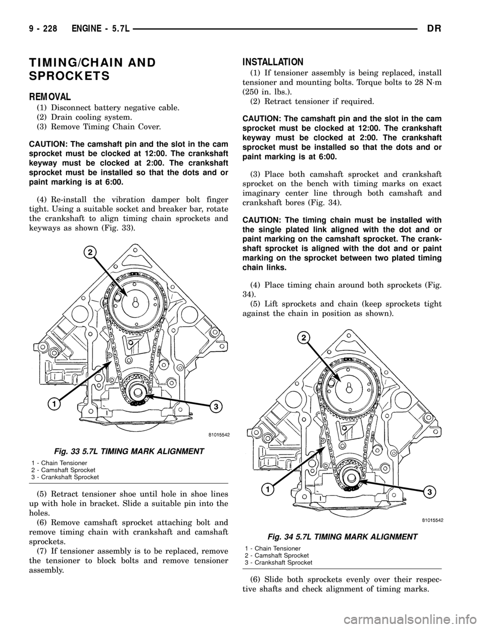
CAUTION: The camshaft pin and the slot in the cam
sprocket must be clocked at 12:00. The crankshaft
keyway must be clocked at 2:00. The crankshaft
sprocket must be installed so that the dots and or
paint marking is at 6:00.
(4) Re-install the vibration damper bolt finger
tight. Using a suitable socket and breaker bar, rotate
the crankshaft to align timing chain sprockets and
keyways as shown (Fig. 33).
(5) Retract tensioner shoe until hole in shoe lines
up with hole in bracket. Slide a suitable pin into the
holes.
(6) Remove camshaft sprocket attaching bolt and
remove timing chain with crankshaft and camshaft
sprockets.
(7) If tensioner assembly is to be replaced, remove
the tensioner to block bolts and remove tensioner
assembly.
INSTALLATION
(1) If tensioner assembly is being replaced, install
tensioner and mounting bolts. Torque bolts to 28 N´m
(250 in. lbs.).
(2) Retract tensioner if required.
CAUTION: The camshaft pin and the slot in the cam
sprocket must be clocked at 12:00. The crankshaft
keyway must be clocked at 2:00. The crankshaft
sprocket must be installed so that the dots and or
paint marking is at 6:00.
(3) Place both camshaft sprocket and crankshaft
sprocket on the bench with timing marks on exact
imaginary center line through both camshaft and
crankshaft bores (Fig. 34).
CAUTION: The timing chain must be installed with
the single plated link aligned with the dot and or
paint marking on the camshaft sprocket. The crank-
shaft sprocket is aligned with the dot and or paint
marking on the sprocket between two plated timing
chain links.
(4) Place timing chain around both sprockets (Fig.
34).
(5) Lift sprockets and chain (keep sprockets tight
against the chain in position as shown).
(6) Slide both sprockets evenly over their respec-
tive shafts and check alignment of timing marks.
Fig. 33 5.7L TIMING MARK ALIGNMENT
1 - Chain Tensioner
2 - Camshaft Sprocket
3 - Crankshaft Sprocket
Fig. 34 5.7L TIMING MARK ALIGNMENT
1 - Chain Tensioner
2 - Camshaft Sprocket
3 - Crankshaft Sprocket
9 - 228 ENGINE - 5.7LDR
Page 1452 of 2627
(7) Install the camshaft bolt. Tighten the bolt to
122 N´m (90 ft. lbs.) torque.
(8)Remove tensioner pin.Again, verify align-
ment of timing marks.
(9) Install the oil pump(Refer to 9 - ENGINE/LU-
BRICATION/OIL PUMP - INSTALLATION).
(10) Install the oil pan and pick up(Refer to 9 -
ENGINE/LUBRICATION/OIL PAN - INSTALLA-
TION).
(11) Install the timing chain cover(Refer to 9 -
ENGINE/VALVE TIMING/TIMING BELT / CHAIN
COVER(S) - INSTALLATION).
(12) Fill cooling system(Refer to 7 - COOLING -
STANDARD PROCEDURE).
(13) Connect battery negative cable.
(14) Start engine and check for oil and coolant
leaks.TIMING CHAIN/TENSIONER
DESCRIPTION
The timing chain tensioner is a stamped steel con-
stant tension mechanical design. It is mounted to the
front of the engine, behind the timing chain drive.
OPERATION
The timing chain tension is maintained by routing
the timing chain through the tensioner assembly. A
nylon covered spring steel arm presses on the timing
chain maintaining the correct chain tension.
DRENGINE - 5.7L 9 - 229
TIMING/CHAIN AND SPROCKETS (Continued)
Page 1453 of 2627
ENGINE 5.9L DIESEL
TABLE OF CONTENTS
page page
ENGINE 5.9L DIESEL
DESCRIPTION........................232
DIAGNOSIS AND TESTING
DIAGNOSIS AND TESTINGÐENGINE
DIAGNOSIS - MECHANICAL............233
DIAGNOSIS AND TESTINGÐSMOKE
DIAGNOSIS CHARTS.................236
DIAGNOSIS AND TESTING - CYLINDER
COMPRESSION/LEAKAGE TESTS.......239
STANDARD PROCEDURE
STANDARD PROCEDURE - FORM-IN-
PLACE GASKETS AND SEALERS........239
STANDARD PROCEDURE - REPAIR
DAMAGED OR WORN THREADS........240
STANDARD PROCEDUREÐHYDROSTATIC
LOCK..............................240
REMOVAL
REMOVAL - ENGINE..................241
REMOVALÐCRANKCASE BREATHER....242
INSTALLATION
INSTALLATION - ENGINE..............242
INSTALLATIONÐCRANKCASE BREATHER . 243
SPECIFICATIONS
SPECIFICATIONS - 5.9L DIESEL.........244
TORQUE...........................245
SPECIAL TOOLS
5.9L DIESEL ENGINE.................246
ENGINE DATA PLATE
DESCRIPTION........................248
AIR CLEANER ELEMENT
REMOVAL............................248
INSTALLATION........................249
CYLINDER HEAD
DESCRIPTION........................249
REMOVAL............................249
CLEANING
CLEANINGÐCYLINDER HEAD..........251
CLEANINGÐCROSSHEADS............251
CLEANINGÐPUSHRODS..............252
INSPECTION
INSPECTION - CYLINDER HEAD.........252
INSPECTIONÐCROSSHEADS..........252
INSPECTIONÐPUSHRODS.............253
INSTALLATION........................253
CYLINDER HEAD COVER(S)
REMOVAL
REMOVALÐCYLINDER HEAD COVER....255
REMOVALÐROCKER HOUSING.........255
CLEANING...........................255INSPECTION.........................255
INSTALLATION
INSTALLATIONÐCYLINDER HEAD COVER . 255
INSTALLATION - ROCKER HOUSING.....255
INTAKE/EXHAUST VALVES & SEATS
DESCRIPTION........................256
STANDARD PROCEDURE
STANDARD PROCEDURE - VALVES,
GUIDES AND SPRINGS................256
STANDARD PROCEDURE - VALVE LASH
ADJUSTMENT AND VERIFICATION.......259
REMOVAL - VALVE SPRINGS AND SEALS . . . 260
INSTALLATION........................261
ROCKER ARM / ADJUSTER ASSY
DESCRIPTION........................261
REMOVAL............................261
CLEANING...........................262
INSPECTION.........................262
INSTALLATION........................263
ENGINE BLOCK
STANDARD PROCEDURE
STANDARD PROCEDURE - CYLINDER
BLOCK REFACING...................264
STANDARD PROCEDURE - CYLINDER
BORE - DE-GLAZE...................264
STANDARD PROCEDUREÐCYLINDER
BORE REPAIR.......................265
STANDARD PROCEDUREÐCAM BORE
REPAIR ............................267
INSPECTION.........................267
CAMSHAFT & BEARINGS (IN BLOCK)
REMOVAL
REMOVALÐCAMSHAFT BEARINGS......268
REMOVAL - CAMSHAFT...............268
INSPECTION.........................270
INSTALLATION
INSTALLATION - CAMSHAFT BEARINGS . . 271
INSTALLATION - CAMSHAFT............271
CONNECTING ROD BEARINGS
STANDARD PROCEDURE - CONNECTING
ROD BEARING AND CRANKSHAFT
JOURNAL CLEARANCE................272
CRANKSHAFT AND GEAR
DESCRIPTION........................273
REMOVAL - GEAR.....................273
INSTALLATION - GEAR..................273
CRANKSHAFT MAIN BEARINGS
STANDARD PROCEDURE - MAIN BEARING
CLEARANCE........................274
9 - 230 ENGINE 5.9L DIESELDR
Page 1454 of 2627
CRANKSHAFT OIL SEAL - FRONT
REMOVAL............................275
INSTALLATION........................275
CRANKSHAFT OIL SEAL - REAR
REMOVAL............................276
INSTALLATION........................276
CRANKSHAFT REAR OIL SEAL RETAINER
REMOVAL............................277
INSTALLATION........................277
SOLID LIFTERS/TAPPETS
REMOVAL............................279
CLEANING...........................279
INSPECTION.........................279
INSTALLATION........................280
PISTON & CONNECTING ROD
DESCRIPTION........................281
STANDARD PROCEDURE - HEAD GASKET
SELECTION.........................281
REMOVAL............................281
CLEANINGÐPISTON AND CONNECTING
ROD ..............................282
INSPECTION
INSPECTION - PISTONS...............282
INSPECTIONÐCONNECTING ROD.......283
INSTALLATION........................283
PISTON RINGS
STANDARD PROCEDURE - PISTON RING
FITTING............................284
VIBRATION DAMPER
REMOVAL............................285
INSPECTION.........................285
INSTALLATION........................286
FRONT MOUNT
REMOVAL............................286
INSTALLATION........................287
REAR MOUNT
REMOVAL............................288
INSTALLATION........................288
LUBRICATION
DESCRIPTION........................289
OPERATION..........................289
DIAGNOSIS AND TESTINGÐENGINE OIL
PRESSURE.........................289
OIL
STANDARD PROCEDURE
STANDARD PROCEDURE - ENGINE OIL
LEVEL.............................292STANDARD PROCEDURE - ENGINE OIL
SERVICE...........................292
OIL COOLER & LINES
CLEANING
CLEANING AND INSPECTION...........293
OIL FILTER
REMOVAL............................293
INSTALLATION........................293
OIL PAN
REMOVAL............................293
CLEANING...........................293
INSPECTION.........................293
INSTALLATION........................293
OIL PRESSURE RELIEF VALVE
REMOVAL............................294
CLEANING...........................294
INSPECTION.........................294
INSTALLATION........................294
OIL PRESSURE SWITCH
REMOVAL............................294
INSTALLATION........................294
OIL PUMP
REMOVAL............................294
CLEANING...........................295
INSPECTION.........................295
INSTALLATION........................296
INTAKE MANIFOLD
REMOVAL............................297
CLEANING...........................297
INSPECTION.........................297
INSTALLATION........................298
EXHAUST MANIFOLD
REMOVAL............................298
CLEANING...........................298
INSPECTION.........................298
INSTALLATION........................298
VALVE TIMING
STANDARD PROCEDURE - TIMING
VERIFICATION.......................299
GEAR HOUSING
REMOVAL............................299
INSTALLATION........................300
GEAR HOUSING COVER
REMOVAL............................301
INSTALLATION........................301
DRENGINE 5.9L DIESEL 9 - 231
Page 1455 of 2627
ENGINE 5.9L DIESEL
DESCRIPTION
The cylinder block is constructed of cast iron. The
casting is a skirted design which incorporates longi-
tudal ribs for superior strength and noise reduction.
The block incorporates metric straight thread o-ring
fittings at lubrication oil access points. The engine
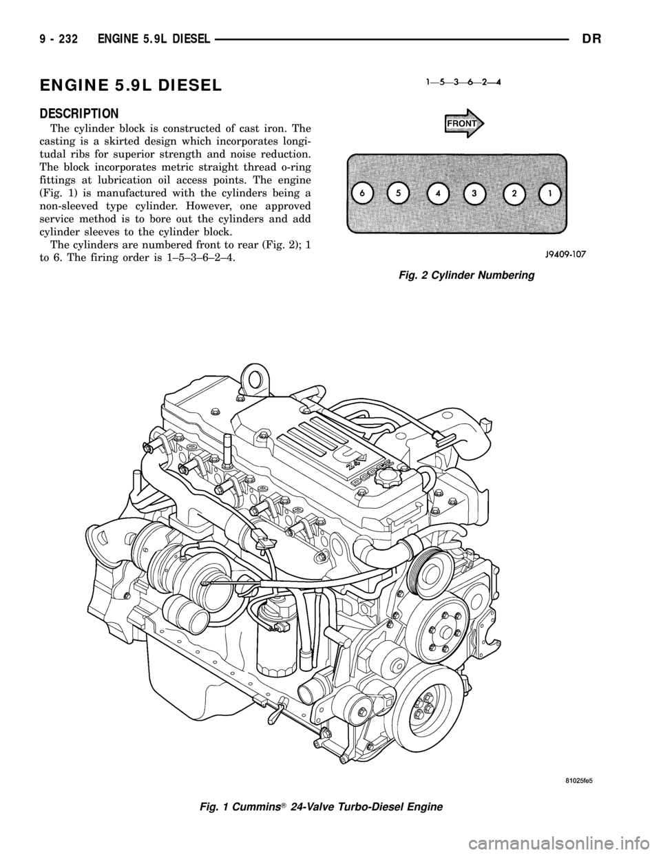
(Fig. 1) is manufactured with the cylinders being a
non-sleeved type cylinder. However, one approved
service method is to bore out the cylinders and add
cylinder sleeves to the cylinder block.
The cylinders are numbered front to rear (Fig. 2); 1
to 6. The firing order is 1±5±3±6±2±4.
Fig. 1 CumminsT24-Valve Turbo-Diesel Engine
Fig. 2 Cylinder Numbering
9 - 232 ENGINE 5.9L DIESELDR
Page 1456 of 2627
DIAGNOSIS AND TESTING
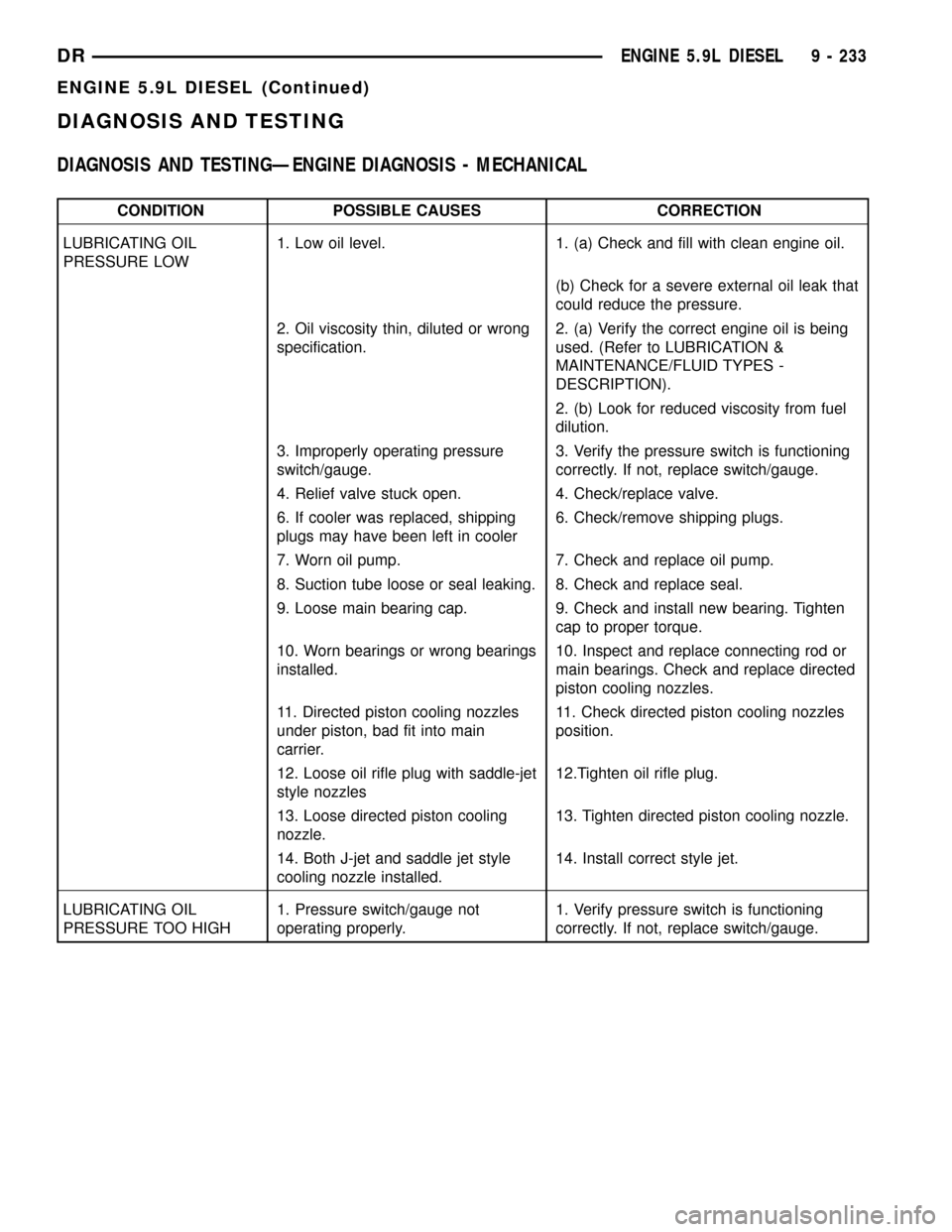
DIAGNOSIS AND TESTINGÐENGINE DIAGNOSIS - MECHANICAL
CONDITION POSSIBLE CAUSES CORRECTION
LUBRICATING OIL
PRESSURE LOW1. Low oil level. 1. (a) Check and fill with clean engine oil.
(b) Check for a severe external oil leak that
could reduce the pressure.
2. Oil viscosity thin, diluted or wrong
specification.2. (a) Verify the correct engine oil is being
used. (Refer to LUBRICATION &
MAINTENANCE/FLUID TYPES -
DESCRIPTION).
2. (b) Look for reduced viscosity from fuel
dilution.
3. Improperly operating pressure
switch/gauge.3. Verify the pressure switch is functioning
correctly. If not, replace switch/gauge.
4. Relief valve stuck open. 4. Check/replace valve.
6. If cooler was replaced, shipping
plugs may have been left in cooler6. Check/remove shipping plugs.
7. Worn oil pump. 7. Check and replace oil pump.
8. Suction tube loose or seal leaking. 8. Check and replace seal.
9. Loose main bearing cap. 9. Check and install new bearing. Tighten
cap to proper torque.
10. Worn bearings or wrong bearings
installed.10. Inspect and replace connecting rod or
main bearings. Check and replace directed
piston cooling nozzles.
11. Directed piston cooling nozzles
under piston, bad fit into main
carrier.11. Check directed piston cooling nozzles
position.
12. Loose oil rifle plug with saddle-jet
style nozzles12.Tighten oil rifle plug.
13. Loose directed piston cooling
nozzle.13. Tighten directed piston cooling nozzle.
14. Both J-jet and saddle jet style
cooling nozzle installed.14. Install correct style jet.
LUBRICATING OIL
PRESSURE TOO HIGH1. Pressure switch/gauge not
operating properly.1. Verify pressure switch is functioning
correctly. If not, replace switch/gauge.
DRENGINE 5.9L DIESEL 9 - 233
ENGINE 5.9L DIESEL (Continued)
Page 1457 of 2627
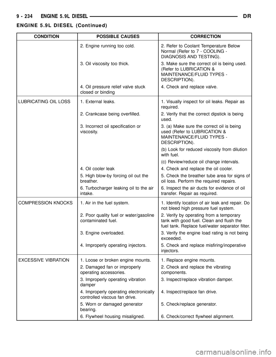
CONDITION POSSIBLE CAUSES CORRECTION
2. Engine running too cold. 2. Refer to Coolant Temperature Below
Normal (Refer to 7 - COOLING -
DIAGNOSIS AND TESTING).
3. Oil viscosity too thick. 3. Make sure the correct oil is being used.
(Refer to LUBRICATION &
MAINTENANCE/FLUID TYPES -
DESCRIPTION).
4. Oil pressure relief valve stuck
closed or binding4. Check and replace valve.
LUBRICATING OIL LOSS 1. External leaks. 1. Visually inspect for oil leaks. Repair as
required.
2. Crankcase being overfilled. 2. Verify that the correct dipstick is being
used.
3. Incorrect oil specification or
viscosity.3. (a) Make sure the correct oil is being
used (Refer to LUBRICATION &
MAINTENANCE/FLUID TYPES -
DESCRIPTION).
(b) Look for reduced viscosity from dilution
with fuel.
(c) Review/reduce oil change intervals.
4. Oil cooler leak 4. Check and replace the oil cooler.
5. High blow-by forcing oil out the
breather.5. Check the breather tube area for signs of
oil loss. Perform the required repairs.
6. Turbocharger leaking oil to the air
intake.6. Inspect the air ducts for evidence of oil
transfer. Repair as required.
COMPRESSION KNOCKS 1. Air in the fuel system. 1. Identify location of air leak and repair. Do
not bleed high pressure fuel system.
2. Poor quality fuel or water/gasoline
contaminated fuel.2. Verify by operating from a temporary
tank with good fuel. Clean and flush the
fuel tank. Replace fuel/water separator filter.
3. Engine overloaded. 3. Verify the engine load rating is not being
exceeded.
4. Improperly operating injectors. 5. Check and replace misfiring/inoperative
injectors.
EXCESSIVE VIBRATION 1. Loose or broken engine mounts. 1. Replace engine mounts.
2. Damaged fan or improperly
operating accessories.2. Check and replace the vibrating
components.
3. Improperly operating vibration
damper3. Inspect/replace vibration damper.
4. Improperly operating electronically
controlled viscous fan drive.4. Inspect/replace fan drive.
5. Worn or damaged generator
bearing.5. Check/replace generator.
6. Flywheel housing misaligned. 6. Check/correct flywheel alignment.
9 - 234 ENGINE 5.9L DIESELDR
ENGINE 5.9L DIESEL (Continued)
Page 1458 of 2627
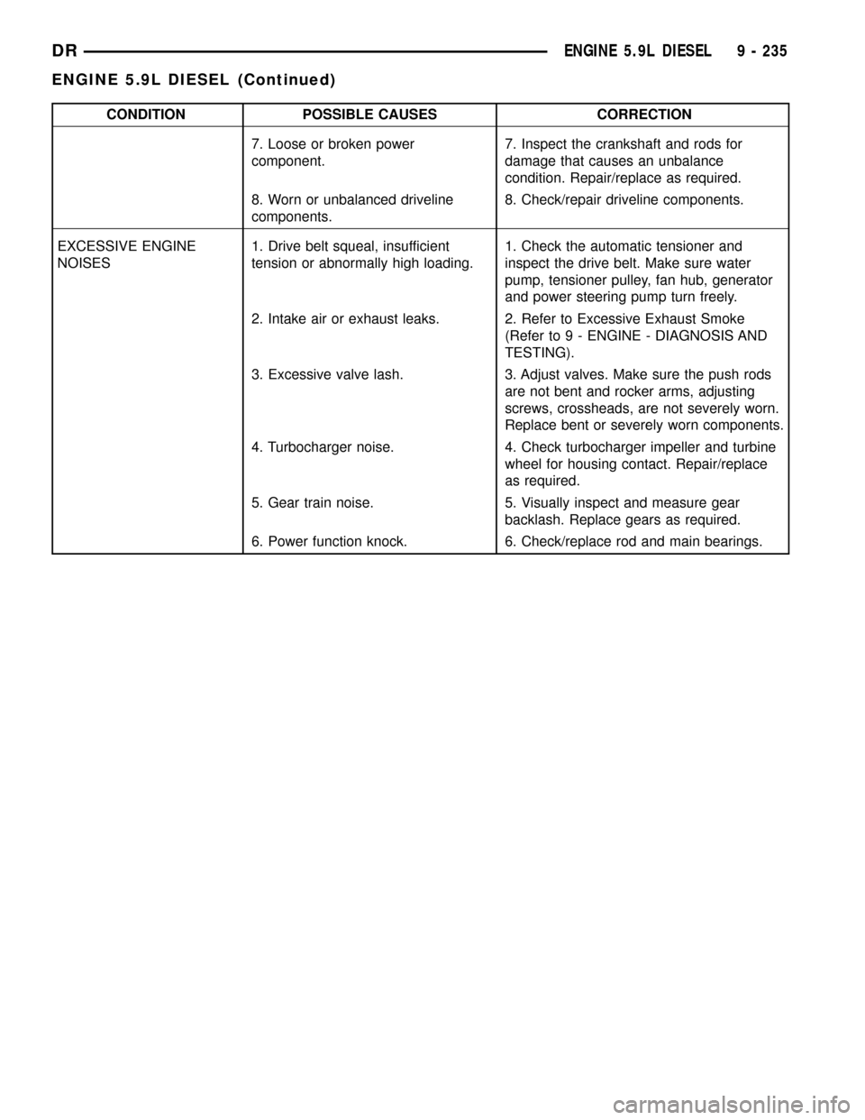
CONDITION POSSIBLE CAUSES CORRECTION
7. Loose or broken power
component.7. Inspect the crankshaft and rods for
damage that causes an unbalance
condition. Repair/replace as required.
8. Worn or unbalanced driveline
components.8. Check/repair driveline components.
EXCESSIVE ENGINE
NOISES1. Drive belt squeal, insufficient
tension or abnormally high loading.1. Check the automatic tensioner and
inspect the drive belt. Make sure water
pump, tensioner pulley, fan hub, generator
and power steering pump turn freely.
2. Intake air or exhaust leaks. 2. Refer to Excessive Exhaust Smoke
(Refer to 9 - ENGINE - DIAGNOSIS AND
TESTING).
3. Excessive valve lash. 3. Adjust valves. Make sure the push rods
are not bent and rocker arms, adjusting
screws, crossheads, are not severely worn.
Replace bent or severely worn components.
4. Turbocharger noise. 4. Check turbocharger impeller and turbine
wheel for housing contact. Repair/replace
as required.
5. Gear train noise. 5. Visually inspect and measure gear
backlash. Replace gears as required.
6. Power function knock. 6. Check/replace rod and main bearings.
DRENGINE 5.9L DIESEL 9 - 235
ENGINE 5.9L DIESEL (Continued)
Page 1459 of 2627
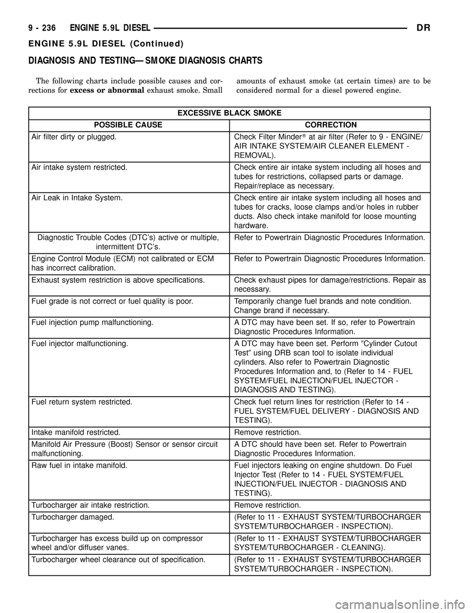
DIAGNOSIS AND TESTINGÐSMOKE DIAGNOSIS CHARTS
The following charts include possible causes and cor-
rections forexcess or abnormalexhaust smoke. Smallamounts of exhaust smoke (at certain times) are to be
considered normal for a diesel powered engine.
EXCESSIVE BLACK SMOKE
POSSIBLE CAUSE CORRECTION
Air filter dirty or plugged. Check Filter MinderTat air filter (Refer to 9 - ENGINE/
AIR INTAKE SYSTEM/AIR CLEANER ELEMENT -
REMOVAL).
Air intake system restricted. Check entire air intake system including all hoses and
tubes for restrictions, collapsed parts or damage.
Repair/replace as necessary.
Air Leak in Intake System. Check entire air intake system including all hoses and
tubes for cracks, loose clamps and/or holes in rubber
ducts. Also check intake manifold for loose mounting
hardware.
Diagnostic Trouble Codes (DTC's) active or multiple,
intermittent DTC's.Refer to Powertrain Diagnostic Procedures Information.
Engine Control Module (ECM) not calibrated or ECM
has incorrect calibration.Refer to Powertrain Diagnostic Procedures Information.
Exhaust system restriction is above specifications. Check exhaust pipes for damage/restrictions. Repair as
necessary.
Fuel grade is not correct or fuel quality is poor. Temporarily change fuel brands and note condition.
Change brand if necessary.
Fuel injection pump malfunctioning. A DTC may have been set. If so, refer to Powertrain
Diagnostic Procedures Information.
Fuel injector malfunctioning. A DTC may have been set. Perform9Cylinder Cutout
Test9using DRB scan tool to isolate individual
cylinders. Also refer to Powertrain Diagnostic
Procedures Information and, to (Refer to 14 - FUEL
SYSTEM/FUEL INJECTION/FUEL INJECTOR -
DIAGNOSIS AND TESTING).
Fuel return system restricted. Check fuel return lines for restriction (Refer to 14 -
FUEL SYSTEM/FUEL DELIVERY - DIAGNOSIS AND
TESTING).
Intake manifold restricted. Remove restriction.
Manifold Air Pressure (Boost) Sensor or sensor circuit
malfunctioning.A DTC should have been set. Refer to Powertrain
Diagnostic Procedures Information.
Raw fuel in intake manifold. Fuel injectors leaking on engine shutdown. Do Fuel
Injector Test (Refer to 14 - FUEL SYSTEM/FUEL
INJECTION/FUEL INJECTOR - DIAGNOSIS AND
TESTING).
Turbocharger air intake restriction. Remove restriction.
Turbocharger damaged. (Refer to 11 - EXHAUST SYSTEM/TURBOCHARGER
SYSTEM/TURBOCHARGER - INSPECTION).
Turbocharger has excess build up on compressor
wheel and/or diffuser vanes.(Refer to 11 - EXHAUST SYSTEM/TURBOCHARGER
SYSTEM/TURBOCHARGER - CLEANING).
Turbocharger wheel clearance out of specification. (Refer to 11 - EXHAUST SYSTEM/TURBOCHARGER
SYSTEM/TURBOCHARGER - INSPECTION).
9 - 236 ENGINE 5.9L DIESELDR
ENGINE 5.9L DIESEL (Continued)
Page 1460 of 2627
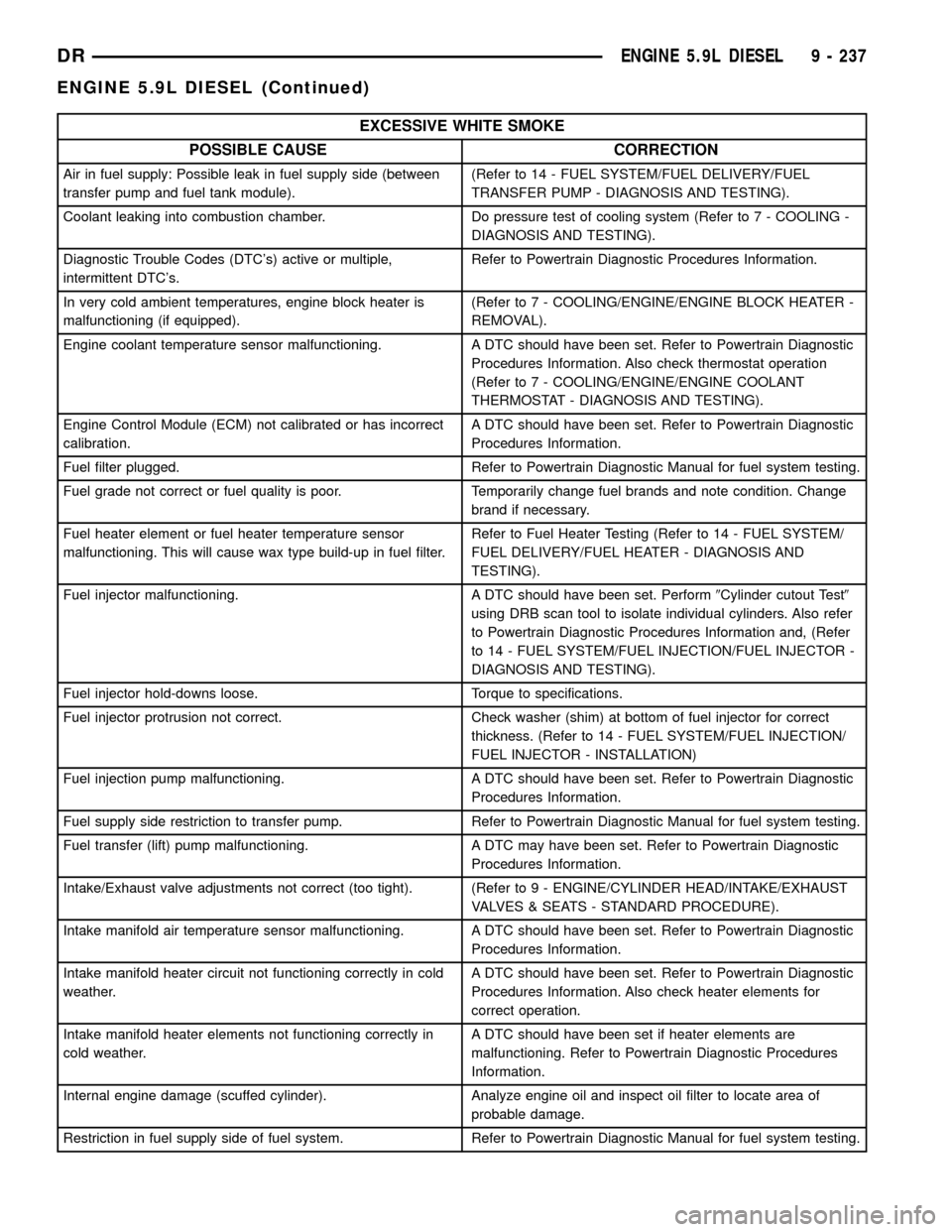
EXCESSIVE WHITE SMOKE
POSSIBLE CAUSE CORRECTION
Air in fuel supply: Possible leak in fuel supply side (between
transfer pump and fuel tank module).(Refer to 14 - FUEL SYSTEM/FUEL DELIVERY/FUEL
TRANSFER PUMP - DIAGNOSIS AND TESTING).
Coolant leaking into combustion chamber. Do pressure test of cooling system (Refer to 7 - COOLING -
DIAGNOSIS AND TESTING).
Diagnostic Trouble Codes (DTC's) active or multiple,
intermittent DTC's.Refer to Powertrain Diagnostic Procedures Information.
In very cold ambient temperatures, engine block heater is
malfunctioning (if equipped).(Refer to 7 - COOLING/ENGINE/ENGINE BLOCK HEATER -
REMOVAL).
Engine coolant temperature sensor malfunctioning. A DTC should have been set. Refer to Powertrain Diagnostic
Procedures Information. Also check thermostat operation
(Refer to 7 - COOLING/ENGINE/ENGINE COOLANT
THERMOSTAT - DIAGNOSIS AND TESTING).
Engine Control Module (ECM) not calibrated or has incorrect
calibration.A DTC should have been set. Refer to Powertrain Diagnostic
Procedures Information.
Fuel filter plugged. Refer to Powertrain Diagnostic Manual for fuel system testing.
Fuel grade not correct or fuel quality is poor. Temporarily change fuel brands and note condition. Change
brand if necessary.
Fuel heater element or fuel heater temperature sensor
malfunctioning. This will cause wax type build-up in fuel filter.Refer to Fuel Heater Testing (Refer to 14 - FUEL SYSTEM/
FUEL DELIVERY/FUEL HEATER - DIAGNOSIS AND
TESTING).
Fuel injector malfunctioning. A DTC should have been set. Perform9Cylinder cutout Test9
using DRB scan tool to isolate individual cylinders. Also refer
to Powertrain Diagnostic Procedures Information and, (Refer
to 14 - FUEL SYSTEM/FUEL INJECTION/FUEL INJECTOR -
DIAGNOSIS AND TESTING).
Fuel injector hold-downs loose. Torque to specifications.
Fuel injector protrusion not correct. Check washer (shim) at bottom of fuel injector for correct
thickness. (Refer to 14 - FUEL SYSTEM/FUEL INJECTION/
FUEL INJECTOR - INSTALLATION)
Fuel injection pump malfunctioning. A DTC should have been set. Refer to Powertrain Diagnostic
Procedures Information.
Fuel supply side restriction to transfer pump. Refer to Powertrain Diagnostic Manual for fuel system testing.
Fuel transfer (lift) pump malfunctioning. A DTC may have been set. Refer to Powertrain Diagnostic
Procedures Information.
Intake/Exhaust valve adjustments not correct (too tight). (Refer to 9 - ENGINE/CYLINDER HEAD/INTAKE/EXHAUST
VALVES & SEATS - STANDARD PROCEDURE).
Intake manifold air temperature sensor malfunctioning. A DTC should have been set. Refer to Powertrain Diagnostic
Procedures Information.
Intake manifold heater circuit not functioning correctly in cold
weather.A DTC should have been set. Refer to Powertrain Diagnostic
Procedures Information. Also check heater elements for
correct operation.
Intake manifold heater elements not functioning correctly in
cold weather.A DTC should have been set if heater elements are
malfunctioning. Refer to Powertrain Diagnostic Procedures
Information.
Internal engine damage (scuffed cylinder). Analyze engine oil and inspect oil filter to locate area of
probable damage.
Restriction in fuel supply side of fuel system. Refer to Powertrain Diagnostic Manual for fuel system testing.
DRENGINE 5.9L DIESEL 9 - 237
ENGINE 5.9L DIESEL (Continued)