DODGE RAM 1500 1998 2.G Workshop Manual
Manufacturer: DODGE, Model Year: 1998, Model line: RAM 1500, Model: DODGE RAM 1500 1998 2.GPages: 2627
Page 1631 of 2627
FUEL TANK
DESCRIPTION - DIESEL
The fuel tank is similar to the tank used with gas-
oline powered models. The tank is equipped with a
separate fuel return line and a different fuel tank
module for diesel powered models. A fuel tank
mounted, electric fuel pump is not used with diesel
powered models. Refer to Fuel Tank Module for addi-
tional information.
REMOVAL - DIESEL
Fuel Tank Draining
Due to a one-way check valve installed into the
fuel fill opening fitting at the tank, the tank cannot
be drained conventionally at the fill cap.
(1) Raise vehicle.
(2) If vehicle is equipped with 4 doors and a 6 foot
(short) box, remove left-rear tire/wheel.
(3) Thoroughly clean area at top of fuel tank
around fuel tank module.
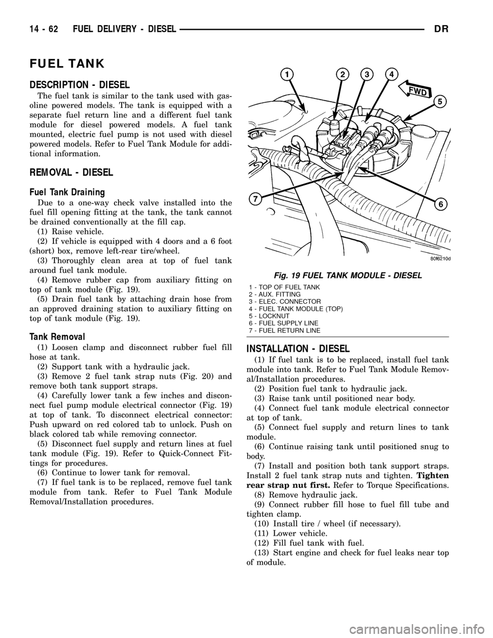
(4) Remove rubber cap from auxiliary fitting on
top of tank module (Fig. 19).
(5) Drain fuel tank by attaching drain hose from
an approved draining station to auxiliary fitting on
top of tank module (Fig. 19).
Tank Removal
(1) Loosen clamp and disconnect rubber fuel fill
hose at tank.
(2) Support tank with a hydraulic jack.
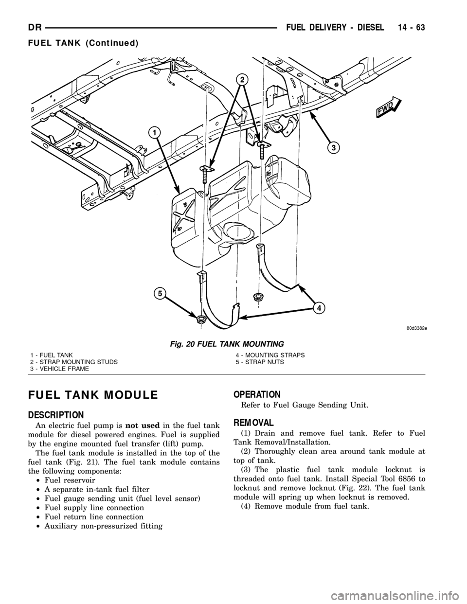
(3) Remove 2 fuel tank strap nuts (Fig. 20) and
remove both tank support straps.
(4) Carefully lower tank a few inches and discon-
nect fuel pump module electrical connector (Fig. 19)
at top of tank. To disconnect electrical connector:
Push upward on red colored tab to unlock. Push on
black colored tab while removing connector.
(5) Disconnect fuel supply and return lines at fuel
tank module (Fig. 19). Refer to Quick-Connect Fit-
tings for procedures.
(6) Continue to lower tank for removal.
(7) If fuel tank is to be replaced, remove fuel tank
module from tank. Refer to Fuel Tank Module
Removal/Installation procedures.INSTALLATION - DIESEL
(1) If fuel tank is to be replaced, install fuel tank
module into tank. Refer to Fuel Tank Module Remov-
al/Installation procedures.
(2) Position fuel tank to hydraulic jack.
(3) Raise tank until positioned near body.
(4) Connect fuel tank module electrical connector
at top of tank.
(5) Connect fuel supply and return lines to tank
module.
(6) Continue raising tank until positioned snug to
body.
(7) Install and position both tank support straps.
Install 2 fuel tank strap nuts and tighten.Tighten
rear strap nut first.Refer to Torque Specifications.
(8) Remove hydraulic jack.
(9) Connect rubber fill hose to fuel fill tube and
tighten clamp.
(10) Install tire / wheel (if necessary).
(11) Lower vehicle.
(12) Fill fuel tank with fuel.
(13) Start engine and check for fuel leaks near top
of module.
Fig. 19 FUEL TANK MODULE - DIESEL
1 - TOP OF FUEL TANK
2 - AUX. FITTING
3 - ELEC. CONNECTOR
4 - FUEL TANK MODULE (TOP)
5 - LOCKNUT
6 - FUEL SUPPLY LINE
7 - FUEL RETURN LINE
14 - 62 FUEL DELIVERY - DIESELDR
Page 1632 of 2627
FUEL TANK MODULE
DESCRIPTION
An electric fuel pump isnot usedin the fuel tank
module for diesel powered engines. Fuel is supplied
by the engine mounted fuel transfer (lift) pump.
The fuel tank module is installed in the top of the
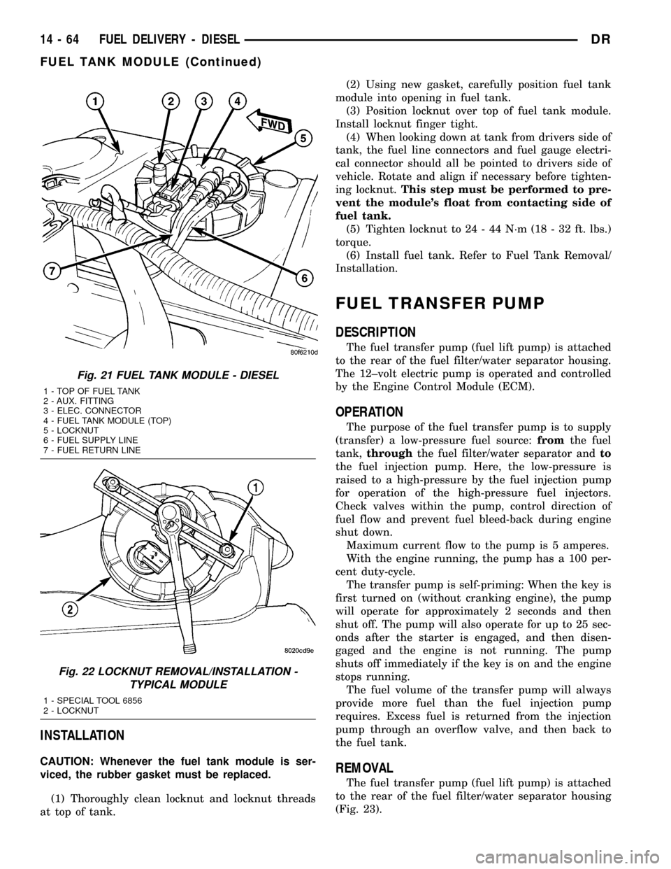
fuel tank (Fig. 21). The fuel tank module contains
the following components:
²Fuel reservoir
²A separate in-tank fuel filter
²Fuel gauge sending unit (fuel level sensor)
²Fuel supply line connection
²Fuel return line connection
²Auxiliary non-pressurized fitting
OPERATION
Refer to Fuel Gauge Sending Unit.
REMOVAL
(1) Drain and remove fuel tank. Refer to Fuel
Tank Removal/Installation.
(2) Thoroughly clean area around tank module at
top of tank.
(3) The plastic fuel tank module locknut is
threaded onto fuel tank. Install Special Tool 6856 to
locknut and remove locknut (Fig. 22). The fuel tank
module will spring up when locknut is removed.
(4) Remove module from fuel tank.
Fig. 20 FUEL TANK MOUNTING
1 - FUEL TANK
2 - STRAP MOUNTING STUDS
3 - VEHICLE FRAME4 - MOUNTING STRAPS
5 - STRAP NUTS
DRFUEL DELIVERY - DIESEL 14 - 63
FUEL TANK (Continued)
Page 1633 of 2627
INSTALLATION
CAUTION: Whenever the fuel tank module is ser-
viced, the rubber gasket must be replaced.
(1) Thoroughly clean locknut and locknut threads
at top of tank.(2) Using new gasket, carefully position fuel tank
module into opening in fuel tank.
(3) Position locknut over top of fuel tank module.
Install locknut finger tight.
(4) When looking down at tank from drivers side of
tank, the fuel line connectors and fuel gauge electri-
cal connector should all be pointed to drivers side of
vehicle. Rotate and align if necessary before tighten-
ing locknut.This step must be performed to pre-
vent the module's float from contacting side of
fuel tank.
(5) Tighten locknut to 24 - 44 N´m (18 - 32 ft. lbs.)
torque.
(6) Install fuel tank. Refer to Fuel Tank Removal/
Installation.
FUEL TRANSFER PUMP
DESCRIPTION
The fuel transfer pump (fuel lift pump) is attached
to the rear of the fuel filter/water separator housing.
The 12±volt electric pump is operated and controlled
by the Engine Control Module (ECM).
OPERATION
The purpose of the fuel transfer pump is to supply
(transfer) a low-pressure fuel source:fromthe fuel
tank,throughthe fuel filter/water separator andto
the fuel injection pump. Here, the low-pressure is
raised to a high-pressure by the fuel injection pump
for operation of the high-pressure fuel injectors.
Check valves within the pump, control direction of
fuel flow and prevent fuel bleed-back during engine
shut down.
Maximum current flow to the pump is 5 amperes.
With the engine running, the pump has a 100 per-
cent duty-cycle.
The transfer pump is self-priming: When the key is
first turned on (without cranking engine), the pump
will operate for approximately 2 seconds and then
shut off. The pump will also operate for up to 25 sec-
onds after the starter is engaged, and then disen-
gaged and the engine is not running. The pump
shuts off immediately if the key is on and the engine
stops running.
The fuel volume of the transfer pump will always
provide more fuel than the fuel injection pump
requires. Excess fuel is returned from the injection
pump through an overflow valve, and then back to
the fuel tank.
REMOVAL
The fuel transfer pump (fuel lift pump) is attached
to the rear of the fuel filter/water separator housing
(Fig. 23).
Fig. 21 FUEL TANK MODULE - DIESEL
1 - TOP OF FUEL TANK
2 - AUX. FITTING
3 - ELEC. CONNECTOR
4 - FUEL TANK MODULE (TOP)
5 - LOCKNUT
6 - FUEL SUPPLY LINE
7 - FUEL RETURN LINE
Fig. 22 LOCKNUT REMOVAL/INSTALLATION -
TYPICAL MODULE
1 - SPECIAL TOOL 6856
2 - LOCKNUT
14 - 64 FUEL DELIVERY - DIESELDR
FUEL TANK MODULE (Continued)
Page 1634 of 2627
(1) Drain fuel from fuel filter housing. Refer to
Fuel Filter/Water Separator - Removal. See Draining.
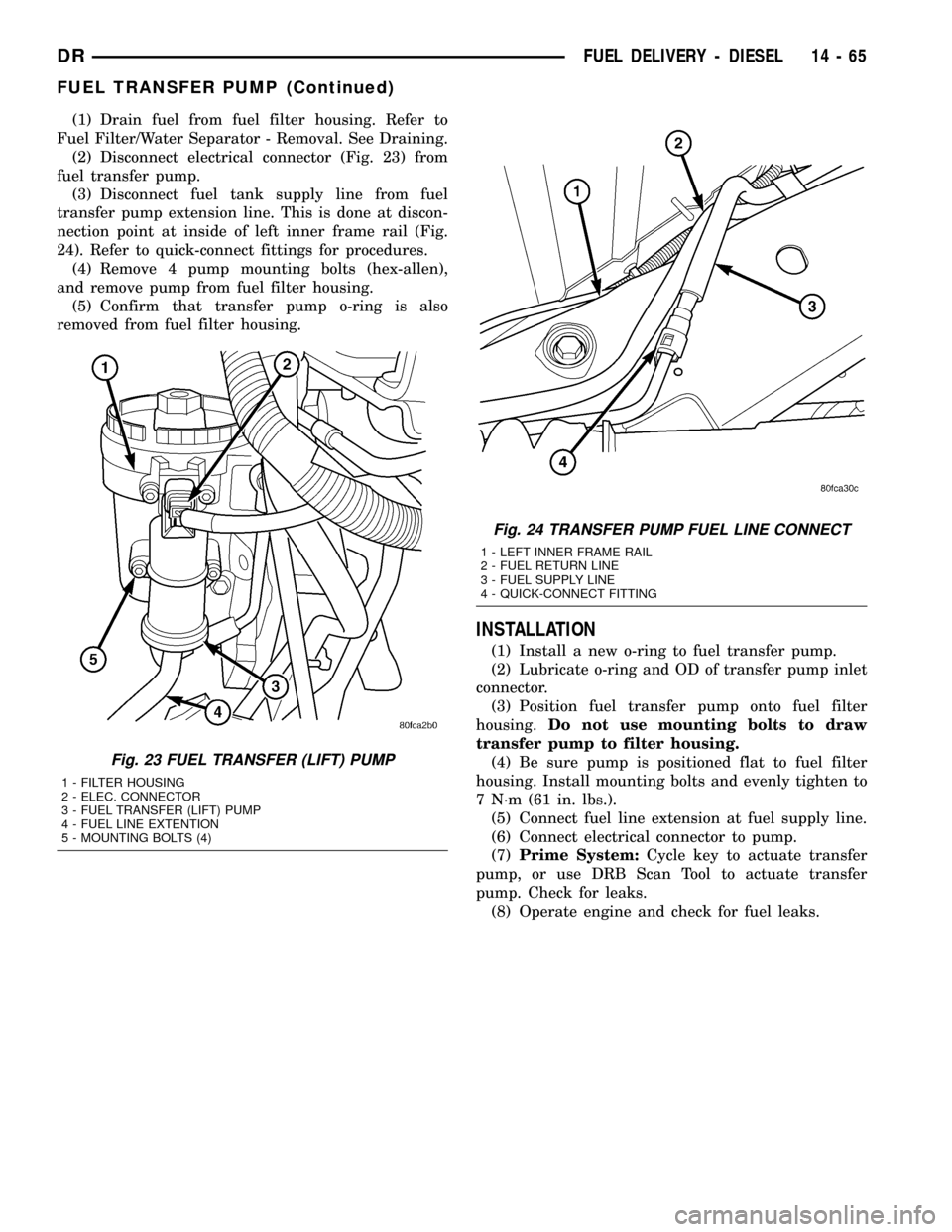
(2) Disconnect electrical connector (Fig. 23) from
fuel transfer pump.
(3) Disconnect fuel tank supply line from fuel
transfer pump extension line. This is done at discon-
nection point at inside of left inner frame rail (Fig.
24). Refer to quick-connect fittings for procedures.
(4) Remove 4 pump mounting bolts (hex-allen),
and remove pump from fuel filter housing.
(5) Confirm that transfer pump o-ring is also
removed from fuel filter housing.
INSTALLATION
(1) Install a new o-ring to fuel transfer pump.
(2) Lubricate o-ring and OD of transfer pump inlet
connector.
(3) Position fuel transfer pump onto fuel filter
housing.Do not use mounting bolts to draw
transfer pump to filter housing.
(4) Be sure pump is positioned flat to fuel filter
housing. Install mounting bolts and evenly tighten to
7 N´m (61 in. lbs.).
(5) Connect fuel line extension at fuel supply line.
(6) Connect electrical connector to pump.
(7)Prime System:Cycle key to actuate transfer
pump, or use DRB Scan Tool to actuate transfer
pump. Check for leaks.
(8) Operate engine and check for fuel leaks.
Fig. 23 FUEL TRANSFER (LIFT) PUMP
1 - FILTER HOUSING
2 - ELEC. CONNECTOR
3 - FUEL TRANSFER (LIFT) PUMP
4 - FUEL LINE EXTENTION
5 - MOUNTING BOLTS (4)
Fig. 24 TRANSFER PUMP FUEL LINE CONNECT
1 - LEFT INNER FRAME RAIL
2 - FUEL RETURN LINE
3 - FUEL SUPPLY LINE
4 - QUICK-CONNECT FITTING
DRFUEL DELIVERY - DIESEL 14 - 65
FUEL TRANSFER PUMP (Continued)
Page 1635 of 2627
CASCADE OVERFLOW VALVE
DESCRIPTION
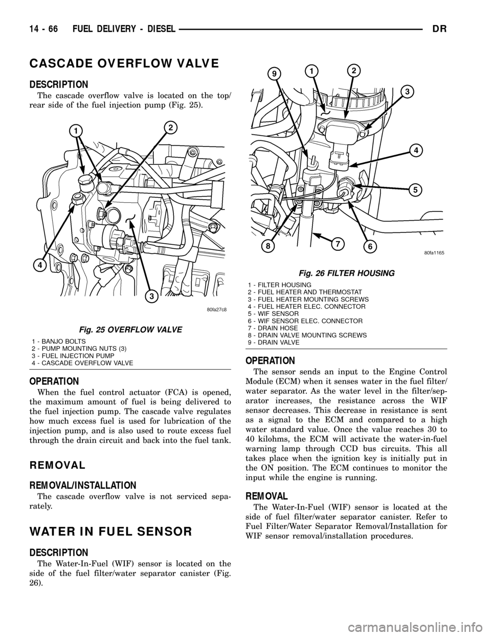
The cascade overflow valve is located on the top/
rear side of the fuel injection pump (Fig. 25).
OPERATION
When the fuel control actuator (FCA) is opened,
the maximum amount of fuel is being delivered to
the fuel injection pump. The cascade valve regulates
how much excess fuel is used for lubrication of the
injection pump, and is also used to route excess fuel
through the drain circuit and back into the fuel tank.
REMOVAL
REMOVAL/INSTALLATION
The cascade overflow valve is not serviced sepa-
rately.
WATER IN FUEL SENSOR
DESCRIPTION
The Water-In-Fuel (WIF) sensor is located on the
side of the fuel filter/water separator canister (Fig.
26).
OPERATION
The sensor sends an input to the Engine Control
Module (ECM) when it senses water in the fuel filter/
water separator. As the water level in the filter/sep-
arator increases, the resistance across the WIF
sensor decreases. This decrease in resistance is sent
as a signal to the ECM and compared to a high
water standard value. Once the value reaches 30 to
40 kilohms, the ECM will activate the water-in-fuel
warning lamp through CCD bus circuits. This all
takes place when the ignition key is initially put in
the ON position. The ECM continues to monitor the
input while the engine is running.
REMOVAL
The Water-In-Fuel (WIF) sensor is located at the
side of fuel filter/water separator canister. Refer to
Fuel Filter/Water Separator Removal/Installation for
WIF sensor removal/installation procedures.
Fig. 25 OVERFLOW VALVE
1 - BANJO BOLTS
2 - PUMP MOUNTING NUTS (3)
3 - FUEL INJECTION PUMP
4 - CASCADE OVERFLOW VALVE
Fig. 26 FILTER HOUSING
1 - FILTER HOUSING
2 - FUEL HEATER AND THERMOSTAT
3 - FUEL HEATER MOUNTING SCREWS
4 - FUEL HEATER ELEC. CONNECTOR
5 - WIF SENSOR
6 - WIF SENSOR ELEC. CONNECTOR
7 - DRAIN HOSE
8 - DRAIN VALVE MOUNTING SCREWS
9 - DRAIN VALVE
14 - 66 FUEL DELIVERY - DIESELDR
Page 1636 of 2627

FUEL DRAIN CIRCUIT
OPERATION
The Fuel Drain Circuit incorporates several
sources of fuel return. Fuel travels from the fuel tank
to the fuel transfer pump and is forced through the
fuel filter. This fuel then travels into the fuel injec-
tion pump. It then goes to a fuel drain line and
returns back to the fuel tank.
The fuel that flows to the fuel pump is pressurized
by a gear pump and internally transferred to the fuel
injection pump. At this point the fuel is channeled
into two passages. One passage sends fuel to the
FCA (Fuel Control Actuator). The other passage
sends fuel to the cascade overflow valve. The over-
flow valve sends some fuel to a lubrication passage.
The rest of the fuel is sent to a drain passage which
connects to an external fuel line.Fuel that travels through the FCA is pressurized
by the fuel injection pump and sent through an
external high pressure fuel line to the fuel rail. At
the fuel rail, fuel is sent to the fuel injectors. If fuel
pressure in the fuel rail becomes excessive, the pres-
sure limiting valve opens and sends fuel through an
external fuel line.
At the fuel injector, fuel that is not injected is used
for lubrication of the fuel injectors. This fuel then
travels through an internal passage that is connected
to the rear of the cylinder head, an then into an
external fuel line. This line is connected to the vehi-
cles fuel return line, and returns excess fuel to the
fuel tank.
DRFUEL DELIVERY - DIESEL 14 - 67
Page 1637 of 2627

FUEL INJECTION - DIESEL
TABLE OF CONTENTS
page page
ACCELERATOR PEDAL POSITION SENSOR
DESCRIPTION.........................68
OPERATION...........................68
REMOVAL.............................68
INSTALLATION.........................71
CAMSHAFT POSITION SENSOR
DESCRIPTION.........................71
OPERATION...........................71
REMOVAL.............................72
INSTALLATION.........................72
CRANKSHAFT POSITION SENSOR
DESCRIPTION.........................72
OPERATION...........................72
REMOVAL.............................73
INSTALLATION.........................73
FUEL CONTROL ACTUATOR
DESCRIPTION.........................74
OPERATION...........................74
REMOVAL.............................74
FUEL INJECTOR
DESCRIPTION.........................74
OPERATION...........................74
REMOVAL.............................75
INSTALLATION.........................77
FUEL INJECTOR RAIL
DESCRIPTION.........................78
OPERATION...........................78
REMOVAL.............................78
INSTALLATION.........................78INLET AIR TEMPERATURE SENSOR/
PRESSURE SENSOR
DESCRIPTION.........................79
OPERATION...........................79
REMOVAL.............................79
INSTALLATION.........................79
INTAKE AIR HEATER
DESCRIPTION.........................80
OPERATION...........................80
REMOVAL.............................80
INSTALLATION.........................80
INTAKE AIR HEATER RELAY
DESCRIPTION.........................82
OPERATION...........................82
REMOVAL.............................82
INSTALLATION.........................82
INTAKE AIR TEMPERATURE SENSOR/MAP
SENSOR
DESCRIPTION.........................82
OPERATION...........................82
REMOVAL.............................82
INSTALLATION.........................82
MAP SENSOR
DESCRIPTION.........................83
THROTTLE CONTROL CABLE
REMOVAL.............................83
INSTALLATION.........................84
PTO SWITCH
DESCRIPTION.........................85
OPERATION...........................85
ACCELERATOR PEDAL
POSITION SENSOR
DESCRIPTION
Engine Mounted Sensor:The APPS assembly is
located at the top-left-front of the engine. A plastic
cover is used to cover the assembly. The actual sen-
sor is located behind its mounting bracket.
Battery Tray Mounted Sensor:The Accelerator
Pedal Position Sensor (APPS) assembly is located
under the vehicle battery tray. A cable connects the
assembly to the accelerator pedal. A plastic cover
with a movable door is used to cover the assembly.
OPERATION
Engine Mounted Sensor:The Accelerator Pedal
Position Sensor (APPS) is a linear potentiometer. Itprovides the Engine Control Module (ECM) with a
DC voltage signal proportional to the angle, or posi-
tion of the accelerator pedal.
Battery Tray Mounted Sensor:The APPS pro-
vides the ECM with two DC voltage signals which
change as the position of the accelerator changes.
One of the DC voltage signals will be half the voltage
of the other signal.
REMOVAL
Engine Mounted Sensor :
The APPS is serviced (replaced) as one assembly
including the lever, brackets and sensor. The APPS is
calibrated to its mounting bracket. The APPS assem-
bly is located at left-front of engine below plastic
cable/lever/linkage cover (Fig. 1).
14 - 68 FUEL INJECTION - DIESELDR
Page 1638 of 2627
CAUTION: Do not attempt to remove sensor from
its mounting bracket as electronic calibration will
be destroyed (sensor-to-bracket mounting screws
are permanently attached). Two accelerator lever
set screws (Fig. 3) are used to position lever. Do
not attempt to alter positions of these set screws as
electronic calibration will be destroyed.
(1) Disconnect both negative battery cables at both
batteries.
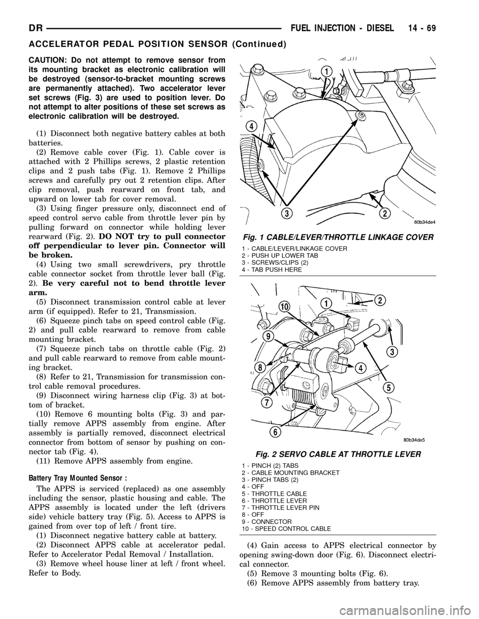
(2) Remove cable cover (Fig. 1). Cable cover is
attached with 2 Phillips screws, 2 plastic retention
clips and 2 push tabs (Fig. 1). Remove 2 Phillips
screws and carefully pry out 2 retention clips. After
clip removal, push rearward on front tab, and
upward on lower tab for cover removal.
(3) Using finger pressure only, disconnect end of
speed control servo cable from throttle lever pin by
pulling forward on connector while holding lever
rearward (Fig. 2).DO NOT try to pull connector
off perpendicular to lever pin. Connector will
be broken.
(4) Using two small screwdrivers, pry throttle
cable connector socket from throttle lever ball (Fig.
2).Be very careful not to bend throttle lever
arm.
(5) Disconnect transmission control cable at lever
arm (if equipped). Refer to 21, Transmission.
(6) Squeeze pinch tabs on speed control cable (Fig.
2) and pull cable rearward to remove from cable
mounting bracket.
(7) Squeeze pinch tabs on throttle cable (Fig. 2)
and pull cable rearward to remove from cable mount-
ing bracket.
(8) Refer to 21, Transmission for transmission con-
trol cable removal procedures.
(9) Disconnect wiring harness clip (Fig. 3) at bot-
tom of bracket.
(10) Remove 6 mounting bolts (Fig. 3) and par-
tially remove APPS assembly from engine. After
assembly is partially removed, disconnect electrical
connector from bottom of sensor by pushing on con-
nector tab (Fig. 4).
(11) Remove APPS assembly from engine.
Battery Tray Mounted Sensor :
The APPS is serviced (replaced) as one assembly
including the sensor, plastic housing and cable. The
APPS assembly is located under the left (drivers
side) vehicle battery tray (Fig. 5). Access to APPS is
gained from over top of left / front tire.
(1) Disconnect negative battery cable at battery.
(2) Disconnect APPS cable at accelerator pedal.
Refer to Accelerator Pedal Removal / Installation.
(3) Remove wheel house liner at left / front wheel.
Refer to Body.(4) Gain access to APPS electrical connector by
opening swing-down door (Fig. 6). Disconnect electri-
cal connector.
(5) Remove 3 mounting bolts (Fig. 6).
(6) Remove APPS assembly from battery tray.
Fig. 1 CABLE/LEVER/THROTTLE LINKAGE COVER
1 - CABLE/LEVER/LINKAGE COVER
2 - PUSH UP LOWER TAB
3 - SCREWS/CLIPS (2)
4 - TAB PUSH HERE
Fig. 2 SERVO CABLE AT THROTTLE LEVER
1 - PINCH (2) TABS
2 - CABLE MOUNTING BRACKET
3 - PINCH TABS (2)
4 - OFF
5 - THROTTLE CABLE
6 - THROTTLE LEVER
7 - THROTTLE LEVER PIN
8 - OFF
9 - CONNECTOR
10 - SPEED CONTROL CABLE
DRFUEL INJECTION - DIESEL 14 - 69
ACCELERATOR PEDAL POSITION SENSOR (Continued)
Page 1639 of 2627
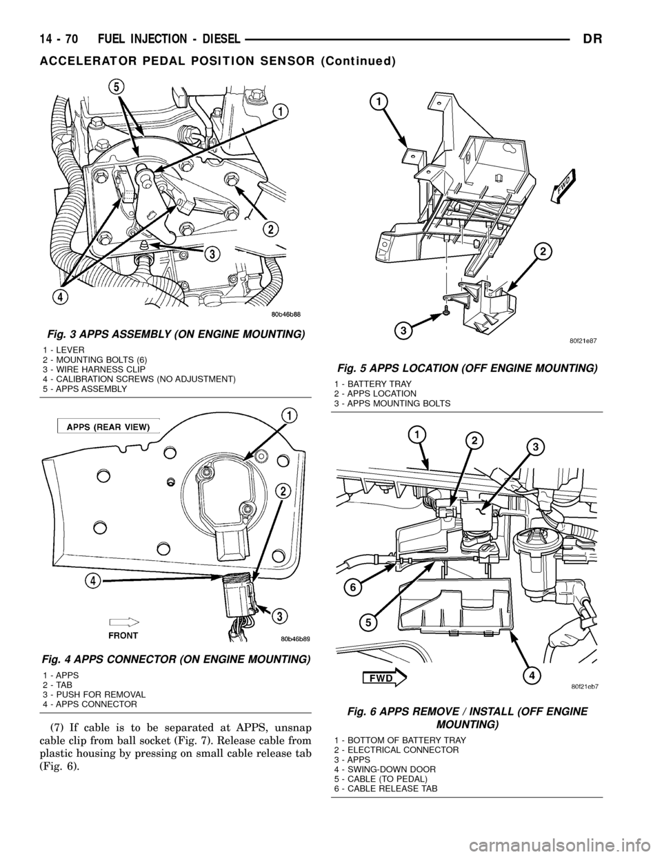
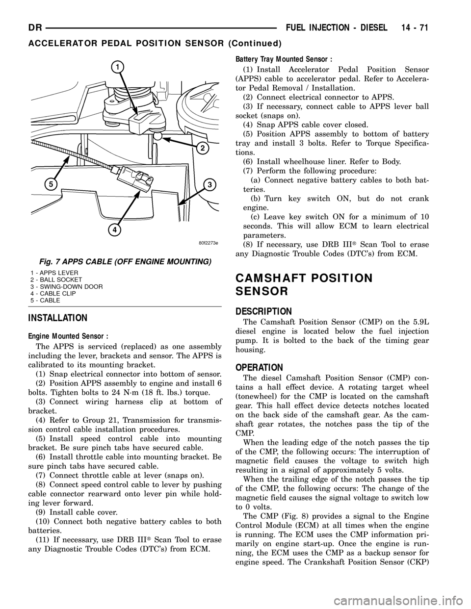
(7) If cable is to be separated at APPS, unsnap
cable clip from ball socket (Fig. 7). Release cable from
plastic housing by pressing on small cable release tab
(Fig. 6).
Fig. 3 APPS ASSEMBLY (ON ENGINE MOUNTING)
1 - LEVER
2 - MOUNTING BOLTS (6)
3 - WIRE HARNESS CLIP
4 - CALIBRATION SCREWS (NO ADJUSTMENT)
5 - APPS ASSEMBLY
Fig. 4 APPS CONNECTOR (ON ENGINE MOUNTING)
1 - APPS
2-TAB
3 - PUSH FOR REMOVAL
4 - APPS CONNECTOR
Fig. 5 APPS LOCATION (OFF ENGINE MOUNTING)
1 - BATTERY TRAY
2 - APPS LOCATION
3 - APPS MOUNTING BOLTS
Fig. 6 APPS REMOVE / INSTALL (OFF ENGINE
MOUNTING)
1 - BOTTOM OF BATTERY TRAY
2 - ELECTRICAL CONNECTOR
3 - APPS
4 - SWING-DOWN DOOR
5 - CABLE (TO PEDAL)
6 - CABLE RELEASE TAB
14 - 70 FUEL INJECTION - DIESELDR
ACCELERATOR PEDAL POSITION SENSOR (Continued)
Page 1640 of 2627
INSTALLATION
Engine Mounted Sensor :
The APPS is serviced (replaced) as one assembly
including the lever, brackets and sensor. The APPS is
calibrated to its mounting bracket.
(1) Snap electrical connector into bottom of sensor.
(2) Position APPS assembly to engine and install 6
bolts. Tighten bolts to 24 N´m (18 ft. lbs.) torque.
(3) Connect wiring harness clip at bottom of
bracket.
(4) Refer to Group 21, Transmission for transmis-
sion control cable installation procedures.
(5) Install speed control cable into mounting
bracket. Be sure pinch tabs have secured cable.
(6) Install throttle cable into mounting bracket. Be
sure pinch tabs have secured cable.
(7) Connect throttle cable at lever (snaps on).
(8) Connect speed control cable to lever by pushing
cable connector rearward onto lever pin while hold-
ing lever forward.
(9) Install cable cover.
(10) Connect both negative battery cables to both
batteries.
(11) If necessary, use DRB IIItScan Tool to erase
any Diagnostic Trouble Codes (DTC's) from ECM.Battery Tray Mounted Sensor :
(1) Install Accelerator Pedal Position Sensor
(APPS) cable to accelerator pedal. Refer to Accelera-
tor Pedal Removal / Installation.
(2) Connect electrical connector to APPS.
(3) If necessary, connect cable to APPS lever ball
socket (snaps on).
(4) Snap APPS cable cover closed.
(5) Position APPS assembly to bottom of battery
tray and install 3 bolts. Refer to Torque Specifica-
tions.
(6) Install wheelhouse liner. Refer to Body.
(7) Perform the following procedure:
(a) Connect negative battery cables to both bat-
teries.
(b) Turn key switch ON, but do not crank
engine.
(c) Leave key switch ON for a minimum of 10
seconds. This will allow ECM to learn electrical
parameters.
(8) If necessary, use DRB IIItScan Tool to erase
any Diagnostic Trouble Codes (DTC's) from ECM.
CAMSHAFT POSITION
SENSOR
DESCRIPTION
The Camshaft Position Sensor (CMP) on the 5.9L
diesel engine is located below the fuel injection
pump. It is bolted to the back of the timing gear
housing.
OPERATION
The diesel Camshaft Position Sensor (CMP) con-
tains a hall effect device. A rotating target wheel
(tonewheel) for the CMP is located on the camshaft
gear. This hall effect device detects notches located
on the back side of the camshaft gear. As the cam-
shaft gear rotates, the notches pass the tip of the
CMP.
When the leading edge of the notch passes the tip
of the CMP, the following occurs: The interruption of
magnetic field causes the voltage to switch high
resulting in a signal of approximately 5 volts.
When the trailing edge of the notch passes the tip
of the CMP, the following occurs: The change of the
magnetic field causes the signal voltage to switch low
to 0 volts.
The CMP (Fig. 8) provides a signal to the Engine
Control Module (ECM) at all times when the engine
is running. The ECM uses the CMP information pri-
marily on engine start-up. Once the engine is run-
ning, the ECM uses the CMP as a backup sensor for
engine speed. The Crankshaft Position Sensor (CKP)
Fig. 7 APPS CABLE (OFF ENGINE MOUNTING)
1 - APPS LEVER
2 - BALL SOCKET
3 - SWING-DOWN DOOR
4 - CABLE CLIP
5 - CABLE
DRFUEL INJECTION - DIESEL 14 - 71
ACCELERATOR PEDAL POSITION SENSOR (Continued)