Front lamp DODGE RAM 1500 1998 2.G User Guide
[x] Cancel search | Manufacturer: DODGE, Model Year: 1998, Model line: RAM 1500, Model: DODGE RAM 1500 1998 2.GPages: 2627
Page 88 of 2627
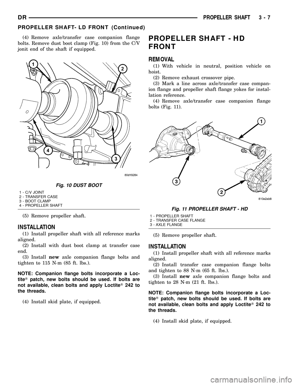
(4) Remove axle/transfer case companion flange
bolts. Remove dust boot clamp (Fig. 10) from the C/V
jonit end of the shaft if equipped.
(5) Remove propeller shaft.
INSTALLATION
(1) Install propeller shaft with all reference marks
aligned.
(2) Install with dust boot clamp at transfer case
end.
(3) Installnewaxle companion flange bolts and
tighten to 115 N´m (85 ft. lbs.).
NOTE: Companion flange bolts incorporate a Loc-
titeTpatch, new bolts should be used. If bolts are
not available, clean bolts and apply LoctiteT242 to
the threads.
(4) Install skid plate, if equipped.
PROPELLER SHAFT - HD
FRONT
REMOVAL
(1) With vehicle in neutral, position vehicle on
hoist.
(2) Remove exhaust crossover pipe.
(3) Mark a line across axle/transfer case compan-
ion flange and propeller shaft flange yokes for instal-
lation reference.
(4) Remove axle/transfer case companion flange
bolts (Fig. 11).
(5) Remove propeller shaft.
INSTALLATION
(1) Install propeller shaft with all reference marks
aligned.
(2) Install transfer case companion flange bolts
and tighten to 88 N´m (65 ft. lbs.).
(3) Installnewaxle companion flange bolts and
tighten to 28 N´m (21 ft. lbs.).
NOTE: Companion flange bolts incorporate a Loc-
titeTpatch, new bolts should be used. If bolts are
not available, clean bolts and apply LoctiteT242 to
the threads.
(4) Install skid plate, if equipped.
Fig. 10 DUST BOOT
1 - C/V JOINT
2 - TRANSFER CASE
3 - BOOT CLAMP
4 - PROPELLER SHAFT
Fig. 11 PROPELLER SHAFT - HD
1 - PROPELLER SHAFT
2 - TRANSFER CASE FLANGE
3 - AXLE FLANGE
DRPROPELLER SHAFT 3 - 7
PROPELLER SHAFT- LD FRONT (Continued)
Page 90 of 2627
CENTER BEARING
REMOVAL
(1) Remove rear propeller shaft.
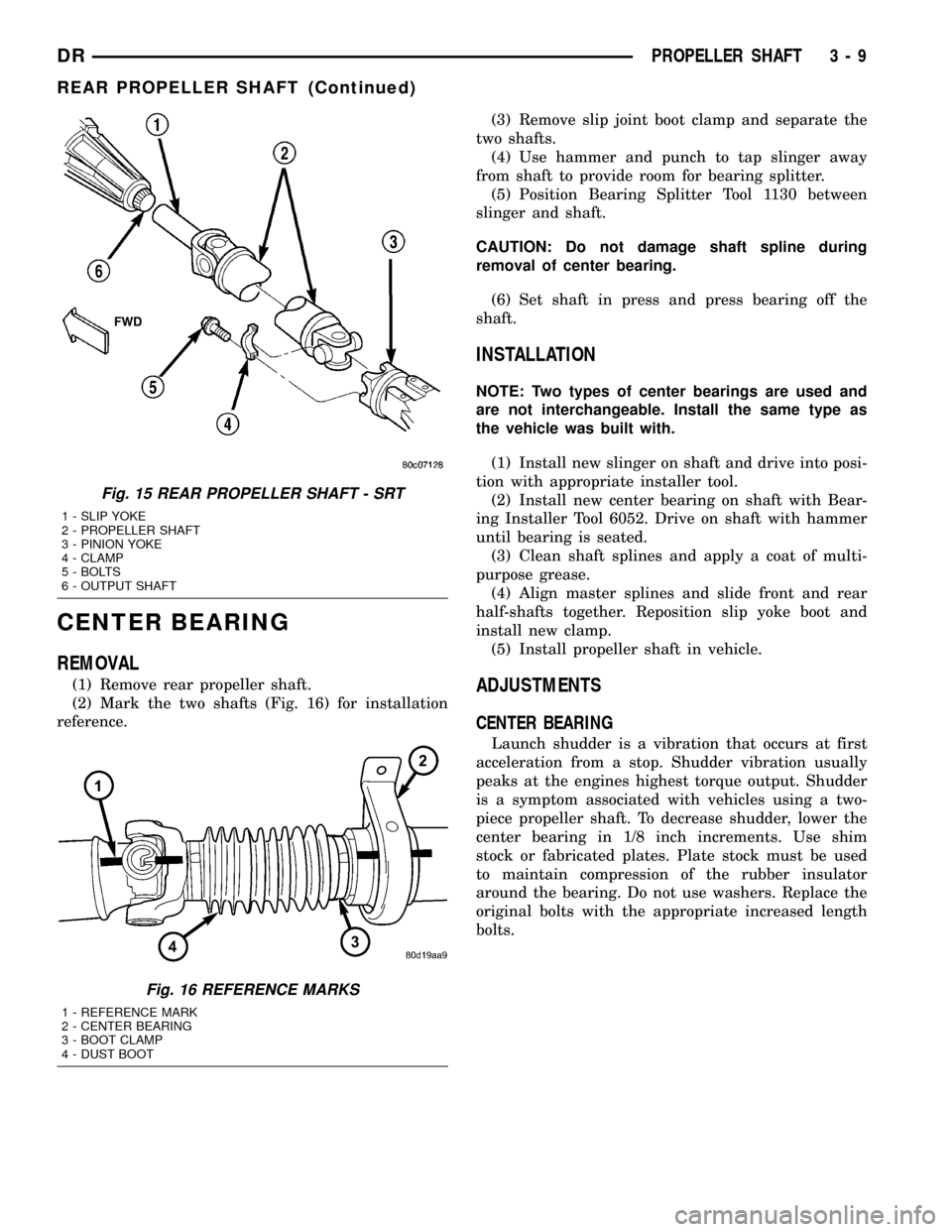
(2) Mark the two shafts (Fig. 16) for installation
reference.(3) Remove slip joint boot clamp and separate the
two shafts.
(4) Use hammer and punch to tap slinger away
from shaft to provide room for bearing splitter.
(5) Position Bearing Splitter Tool 1130 between
slinger and shaft.
CAUTION: Do not damage shaft spline during
removal of center bearing.
(6) Set shaft in press and press bearing off the
shaft.
INSTALLATION
NOTE: Two types of center bearings are used and
are not interchangeable. Install the same type as
the vehicle was built with.
(1) Install new slinger on shaft and drive into posi-
tion with appropriate installer tool.
(2) Install new center bearing on shaft with Bear-
ing Installer Tool 6052. Drive on shaft with hammer
until bearing is seated.
(3) Clean shaft splines and apply a coat of multi-
purpose grease.
(4) Align master splines and slide front and rear
half-shafts together. Reposition slip yoke boot and
install new clamp.
(5) Install propeller shaft in vehicle.
ADJUSTMENTS
CENTER BEARING
Launch shudder is a vibration that occurs at first
acceleration from a stop. Shudder vibration usually
peaks at the engines highest torque output. Shudder
is a symptom associated with vehicles using a two-
piece propeller shaft. To decrease shudder, lower the
center bearing in 1/8 inch increments. Use shim
stock or fabricated plates. Plate stock must be used
to maintain compression of the rubber insulator
around the bearing. Do not use washers. Replace the
original bolts with the appropriate increased length
bolts.
Fig. 15 REAR PROPELLER SHAFT - SRT
1 - SLIP YOKE
2 - PROPELLER SHAFT
3 - PINION YOKE
4 - CLAMP
5 - BOLTS
6 - OUTPUT SHAFT
Fig. 16 REFERENCE MARKS
1 - REFERENCE MARK
2 - CENTER BEARING
3 - BOOT CLAMP
4 - DUST BOOT
DRPROPELLER SHAFT 3 - 9
REAR PROPELLER SHAFT (Continued)
Page 101 of 2627
HALF SHAFT
TABLE OF CONTENTS
page page
HALF SHAFT
CAUTION.............................20
DIAGNOSIS AND TESTING................20
REMOVAL.............................20
INSTALLATION.........................21
SPECIFICATIONS.......................21
SPECIAL TOOLS.......................21CV JOINT-OUTER
REMOVAL.............................22
INSTALLATION.........................23
CV JOINT-INNER
REMOVAL.............................25
INSTALLATION.........................25
HALF SHAFT
CAUTION
CAUTION:: Never grasp half shaft assembly by the
boots. This may cause the boot to pucker or crease
and reduce the service life of the boot.
Avoid over angulating or stroking the C/V joints
when handling the half shaft.
Half shafts exposed to battery acid, transmission
fluid, brake fluid, differential fluid or gasoline may
cause the boots to deteriorate. Failure to heed cau-
tion may result in damage.
DIAGNOSIS AND TESTING
Check inboard and outboard C/V joint for leaking
grease. This is a sign of boot or boot clamp damage.
NOISE/VIBRATION IN TURNS
A clicking noise or vibration in turns could be
caused by a damaged outer C/V or inner tripod joint
seal boot or seal boot clamps. This will result in the
loss/contamination of the joint grease, resulting in
inadequate lubrication of the joint. Noise could also
be caused by another component of the vehicle com-
ing in contact with the half shafts.
CLUNKING NOISE DURING ACCELERATION
This noise may be a damaged or worn C/V joint. A
torn boot or loose/missing clamp on the inner/outer
joint which has allowed the grease to be lost will
damage the C/V joint.
SHUDDER/VIBRATION DURING ACCELERATION
This could be a worn/damaged inner tripod joint or
a sticking tripod joint. Improper wheel alignment
may also cause a shudder or vibration.
VIBRATION AT HIGHWAY SPEEDS
This problem could be a result of out of balance
front tires or tire/wheel runout. Foreign material
(mud, etc.) packed on the backside of the wheel(s)
will also cause a vibration.
REMOVAL
(1) With vehicle in neutral, position vehicle on
hoist.
(2) Remove half shaft hub nut.
(3) Remove brake caliper and rotor.
(4) Position hydraulic jack under lower suspension
arm and raise jack to unload rebound bumper.
(5) Remove lower shock absorber bolt.
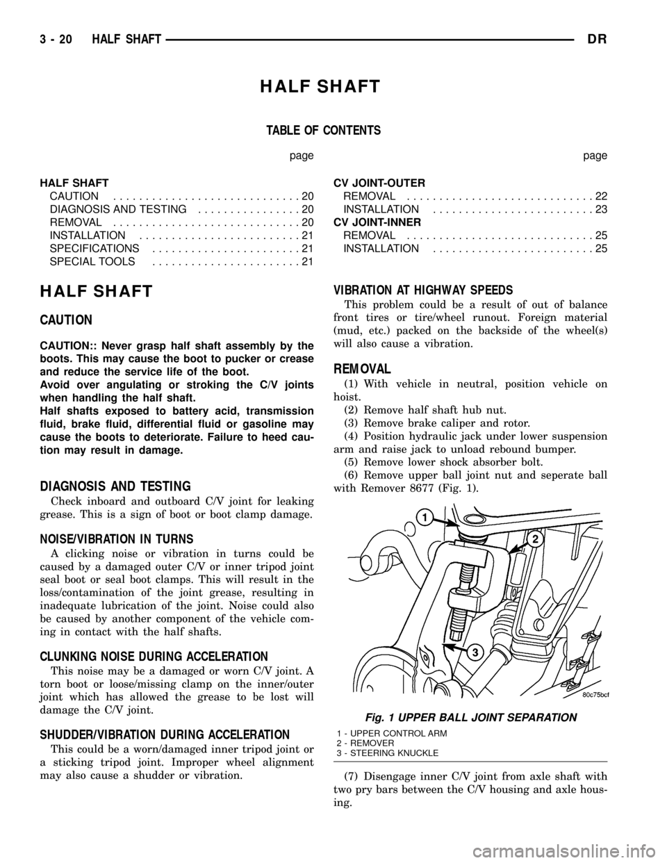
(6) Remove upper ball joint nut and seperate ball
with Remover 8677 (Fig. 1).
(7) Disengage inner C/V joint from axle shaft with
two pry bars between the C/V housing and axle hous-
ing.
Fig. 1 UPPER BALL JOINT SEPARATION
1 - UPPER CONTROL ARM
2 - REMOVER
3 - STEERING KNUCKLE
3 - 20 HALF SHAFTDR
Page 102 of 2627
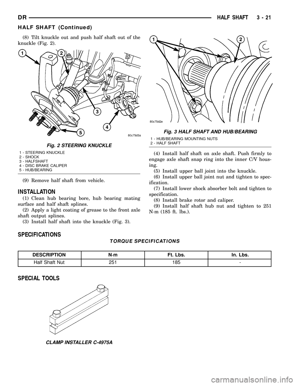
(8) Tilt knuckle out and push half shaft out of the
knuckle (Fig. 2).
(9) Remove half shaft from vehicle.
INSTALLATION
(1) Clean hub bearing bore, hub bearing mating
surface and half shaft splines.
(2) Apply a light coating of grease to the front axle
shaft output splines.
(3) Install half shaft into the knuckle (Fig. 3).(4) Install half shaft on axle shaft. Push firmly to
engage axle shaft snap ring into the inner C/V hous-
ing.
(5) Install upper ball joint into the knuckle.
(6) Install upper ball joint nut and tighten to spec-
ification.
(7) Install lower shock absorber bolt and tighten to
specification.
(8) Install brake rotor and caliper.
(9) Install half shaft hub nut and tighten to 251
N´m (185 ft. lbs.).
SPECIFICATIONS
TORQUE SPECIFICATIONS
DESCRIPTION N´m Ft. Lbs. In. Lbs.
Half Shaft Nut 251 185 -
SPECIAL TOOLS
Fig. 2 STEERING KNUCKLE
1 - STEERING KNUCKLE
2 - SHOCK
3 - HALFSHAFT
4 - DISC BRAKE CALIPER
5 - HUB/BEARING
Fig. 3 HALF SHAFT AND HUB/BEARING
1 - HUB/BEARING MOUNTING NUTS
2 - HALF SHAFT
CLAMP INSTALLER C-4975A
DRHALF SHAFT 3 - 21
HALF SHAFT (Continued)
Page 129 of 2627
INSTALLATION
NOTE: If replacement differential bearings or differ-
ential case are replaced, Refer to adjustments for
Differential Bearing Preload and Gear Backlash pro-
cedures.
(1) Install Spreader W-129-B with the Adapter
Plates 8142-A and install the safety holddown
clamps. Tighten the tool turnbuckle finger-tight.
(2) Install a Pilot Stud L-4438 at the left side of
the differential housing. Attach Dial Indicator C-3339
to pilot stud. Load indicator plunger against the
opposite side of the housing and zero the indicator.
(3) Spread housing and measure the distance with
the dial indicator.
CAUTION: Never spread housing over 0.50 mm
(0.020 in). Failure to heed caution may result in
damage.
(4) Remove dial indicator.
(5) Install differential case in the housing. Ensure
differential bearing cups remain in position on the
bearings and the differential preload shims are
seated in the housing. Tap differential case to ensure
bearings cups are seated in the housing.
(6) Install bearing caps to their original locations
and loosely install cap bolts.
(7) Remove housing spreader.
(8) Tighten the bearing cap bolts to 61 N´m (45 ft.
lbs.).
(9) Install axle shafts.
(10) Apply a bead of orange Mopar Axle RTV seal-
ant or equivalent to the housing cover.
CAUTION: If cover is not installed within 3 to 5 min-
utes, the cover must be cleaned and new RTV
applied. Failure to heed caution may result in dam-
age.
(11) Install cover and tighten bolts in a criss-cross
pattern to 22 N´m (15 ft. lbs.).
(12) Fill differential with lubricant.
DIFFERENTIAL CASE
BEARINGS
REMOVAL
(1) Remove differential from housing.
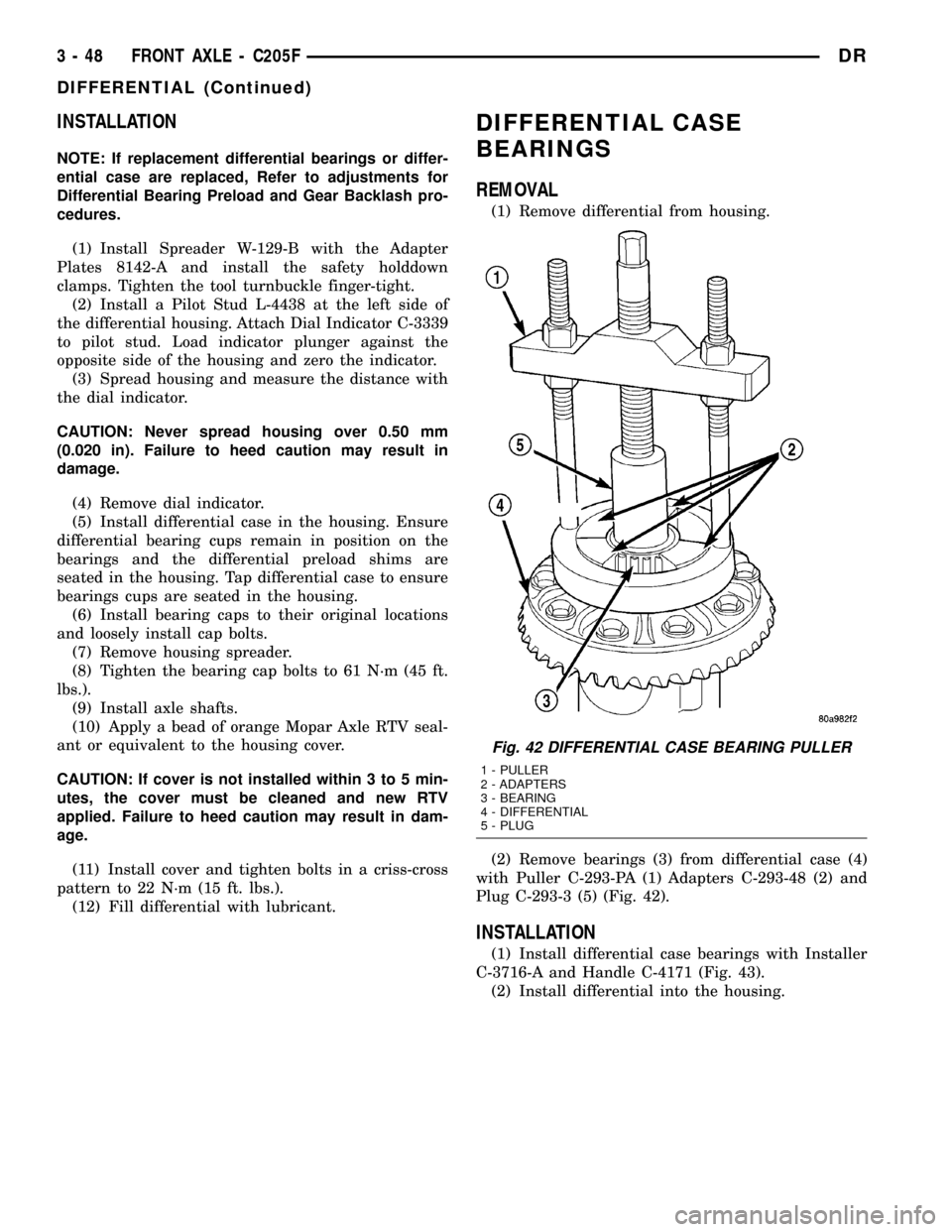
(2) Remove bearings (3) from differential case (4)
with Puller C-293-PA (1) Adapters C-293-48 (2) and
Plug C-293-3 (5) (Fig. 42).
INSTALLATION
(1) Install differential case bearings with Installer
C-3716-A and Handle C-4171 (Fig. 43).
(2) Install differential into the housing.
Fig. 42 DIFFERENTIAL CASE BEARING PULLER
1 - PULLER
2 - ADAPTERS
3 - BEARING
4 - DIFFERENTIAL
5 - PLUG
3 - 48 FRONT AXLE - C205FDR
DIFFERENTIAL (Continued)
Page 149 of 2627
(5) Remove hub bearing from the steering knuckle.
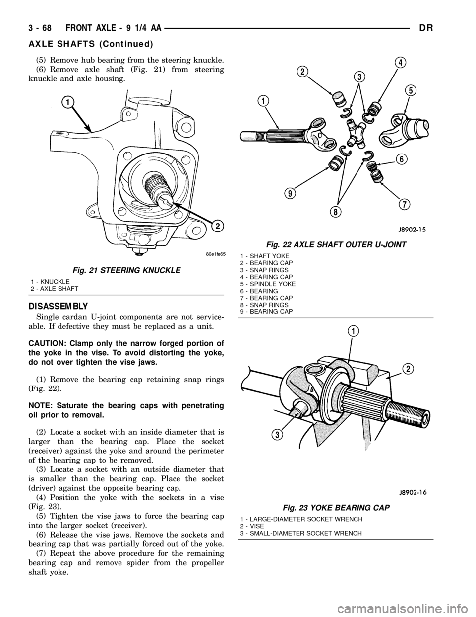
(6) Remove axle shaft (Fig. 21) from steering
knuckle and axle housing.
DISASSEMBLY
Single cardan U-joint components are not service-
able. If defective they must be replaced as a unit.
CAUTION: Clamp only the narrow forged portion of
the yoke in the vise. To avoid distorting the yoke,
do not over tighten the vise jaws.
(1) Remove the bearing cap retaining snap rings
(Fig. 22).
NOTE: Saturate the bearing caps with penetrating
oil prior to removal.
(2) Locate a socket with an inside diameter that is
larger than the bearing cap. Place the socket
(receiver) against the yoke and around the perimeter
of the bearing cap to be removed.
(3) Locate a socket with an outside diameter that
is smaller than the bearing cap. Place the socket
(driver) against the opposite bearing cap.
(4) Position the yoke with the sockets in a vise
(Fig. 23).
(5) Tighten the vise jaws to force the bearing cap
into the larger socket (receiver).
(6) Release the vise jaws. Remove the sockets and
bearing cap that was partially forced out of the yoke.
(7) Repeat the above procedure for the remaining
bearing cap and remove spider from the propeller
shaft yoke.
Fig. 21 STEERING KNUCKLE
1 - KNUCKLE
2 - AXLE SHAFT
Fig. 22 AXLE SHAFT OUTER U-JOINT
1 - SHAFT YOKE
2 - BEARING CAP
3 - SNAP RINGS
4 - BEARING CAP
5 - SPINDLE YOKE
6 - BEARING
7 - BEARING CAP
8 - SNAP RINGS
9 - BEARING CAP
Fig. 23 YOKE BEARING CAP
1 - LARGE-DIAMETER SOCKET WRENCH
2 - VISE
3 - SMALL-DIAMETER SOCKET WRENCH
3 - 68 FRONT AXLE - 9 1/4 AADR
AXLE SHAFTS (Continued)
Page 165 of 2627
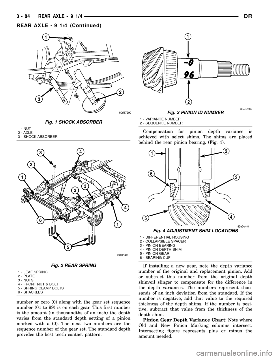
number or zero (0) along with the gear set sequence
number (01 to 99) is on each gear. This first number
is the amount (in thousandths of an inch) the depth
varies from the standard depth setting of a pinion
marked with a (0). The next two numbers are the
sequence number of the gear set. The standard depth
provides the best teeth contact pattern.Compensation for pinion depth variance is
achieved with select shims. The shims are placed
behind the rear pinion bearing. (Fig. 4).
If installing a new gear, note the depth variance
number of the original and replacement pinion. Add
or subtract this number from the original depth
shim/oil slinger to compensate for the difference in
the depth variances. The numbers represent thou-
sands of an inch deviation from the standard. If the
number is negative, add that value to the required
thickness of the depth shims. If the number is posi-
tive, subtract that value from the thickness of the
depth shim.
Pinion Gear Depth Variance Chart: Note where
Old and New Pinion Marking columns intersect.
Intersecting figure represents plus or minus the
amount needed.
Fig. 1 SHOCK ABSORBER
1 - NUT
2 - AXLE
3 - SHOCK ABSORBER
Fig. 2 REAR SPRING
1 - LEAF SPRING
2 - PLATE
3 - NUTS
4 - FRONT NUT & BOLT
5 - SPRING CLAMP BOLTS
6 - SHACKLES
Fig. 3 PINION ID NUMBER
1 - VARIANCE NUMBER
2 - SEQUENCE NUMBER
Fig. 4 ADJUSTMENT SHIM LOCATIONS
1 - DIFFERENTIAL HOUSING
2 - COLLAPSIBLE SPACER
3 - PINION BEARING
4 - PINION DEPTH SHIM
5 - PINION GEAR
6 - BEARING CUP
3 - 84 REAR AXLE-91/4DR
REAR AXLE - 9 1/4 (Continued)
Page 182 of 2627
DIFFERENTIAL TEST
The differential can be tested without removing the
differential case by measuring rotating torque. Make
sure brakes are not dragging during this measure-
ment.
(1) Place blocks in front and rear of both front
wheels.
(2) Raise one rear wheel until it is completely off
the ground.
(3) Engine off, transmission in neutral, and park-
ing brake off.
(4) Remove wheel and bolt Special Tool 6790 or
equivalent tool to studs.
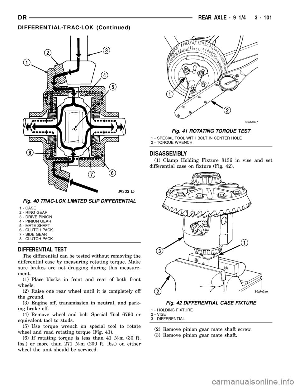
(5) Use torque wrench on special tool to rotate
wheel and read rotating torque (Fig. 41).
(6) If rotating torque is less than 41 N´m (30 ft.
lbs.) or more than 271 N´m (200 ft. lbs.) on either
wheel the unit should be serviced.
DISASSEMBLY
(1) Clamp Holding Fixture 8136 in vise and set
differential case on fixture (Fig. 42).
(2) Remove pinion gear mate shaft screw.
(3) Remove pinion gear mate shaft.
Fig. 40 TRAC-LOK LIMITED SLIP DIFFERENTIAL
1 - CASE
2 - RING GEAR
3 - DRIVE PINION
4 - PINION GEAR
5 - MATE SHAFT
6 - CLUTCH PACK
7 - SIDE GEAR
8 - CLUTCH PACK
Fig. 41 ROTATING TORQUE TEST
1 - SPECIAL TOOL WITH BOLT IN CENTER HOLE
2 - TORQUE WRENCH
Fig. 42 DIFFERENTIAL CASE FIXTURE
1 - HOLDING FIXTURE
2 - VISE
3 - DIFFERENTIAL
DRREAR AXLE - 9 1/4 3 - 101
DIFFERENTIAL-TRAC-LOK (Continued)
Page 196 of 2627
Condition Possible Causes Correction
Axle Noise 1. Insufficient lubricant. 1. Fill differential with the correct fluid
type and quantity.
2. Improper ring gear and pinion
adjustment.2. Check ring gear and pinion contact
pattern. Adjust backlash or pinion
depth.
3. Unmatched ring gear and pinion. 3. Replace gears with a matched ring
gear and pinion.
4. Worn teeth on ring gear and/or
pinion.4. Replace ring gear and pinion.
5. Loose pinion bearings. 5. Adjust pinion bearing pre-load.
6. Loose differential bearings. 6. Adjust differential bearing pre-load.
7. Mis-aligned or sprung ring gear. 7. Measure ring gear run-out. Replace
components as necessary.
8. Loose differential bearing cap
bolts.8. Inspect differential components and
replace as necessary. Ensure that the
bearing caps are torqued tot he
proper specification.
9. Housing not machined properly. 9. Replace housing.
REMOVAL
(1) Raise and support the vehicle.
(2) Position a lift under axle and secure lift to the
axle.
(3) Remove wheels and tires assemblies.
(4) Remove all brake components.
(5) Mark propeller shaft and companion flange for
installation alignment reference.
(6) Remove propeller shaft.
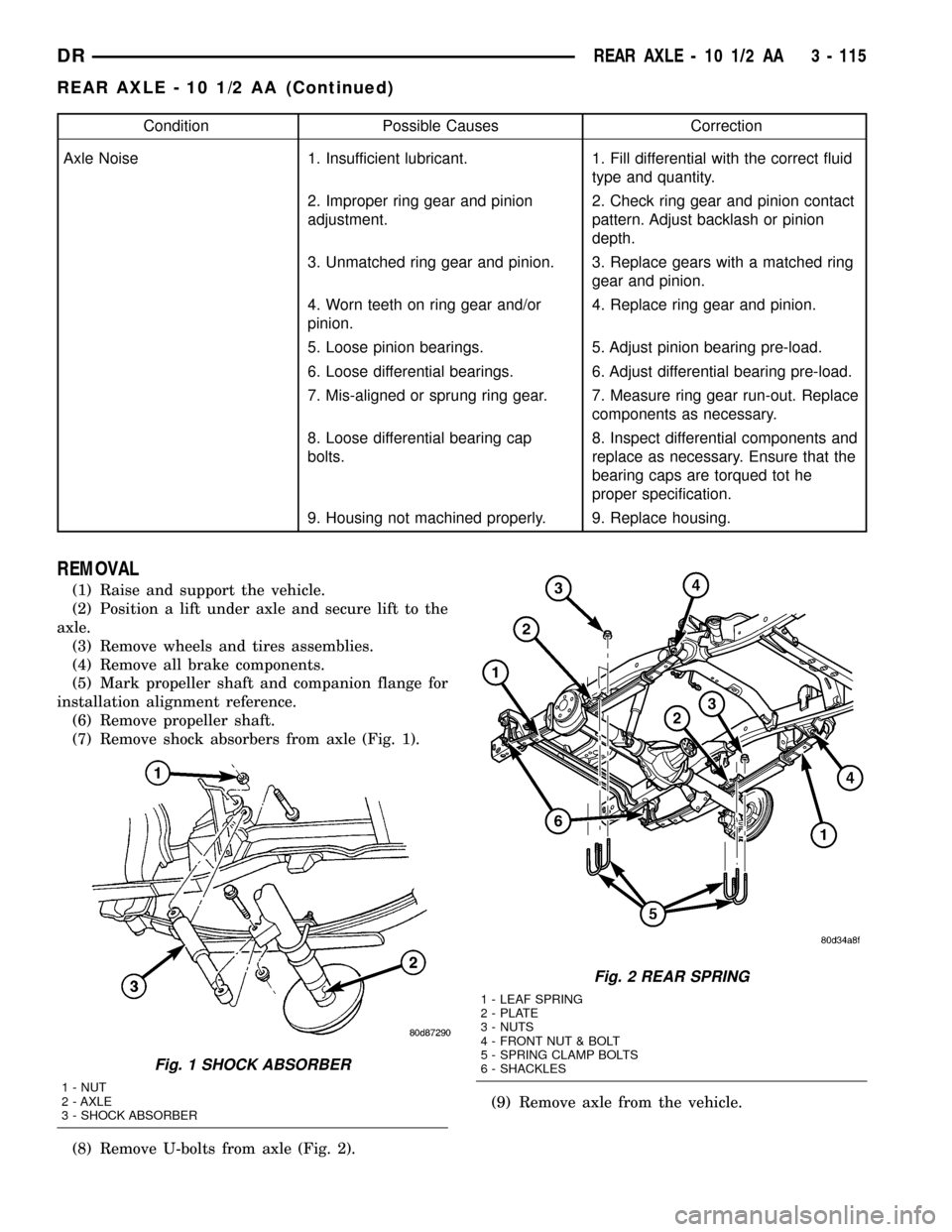
(7) Remove shock absorbers from axle (Fig. 1).
(8) Remove U-bolts from axle (Fig. 2).(9) Remove axle from the vehicle.
Fig. 1 SHOCK ABSORBER
1 - NUT
2 - AXLE
3 - SHOCK ABSORBER
Fig. 2 REAR SPRING
1 - LEAF SPRING
2 - PLATE
3 - NUTS
4 - FRONT NUT & BOLT
5 - SPRING CLAMP BOLTS
6 - SHACKLES
DRREAR AXLE - 10 1/2 AA 3 - 115
REAR AXLE - 10 1/2 AA (Continued)
Page 224 of 2627
Condition Possible Causes Correction
Axle Noise 1. Insufficient lubricant. 1. Fill differential with the correct fluid
type and quantity.
2. Improper ring gear and pinion
adjustment.2. Check ring gear and pinion contact
pattern. Adjust backlash or pinion
depth.
3. Unmatched ring gear and pinion. 3. Replace gears with a matched ring
gear and pinion.
4. Worn teeth on ring gear and/or
pinion.4. Replace ring gear and pinion.
5. Loose pinion bearings. 5. Adjust pinion bearing pre-load.
6. Loose differential bearings. 6. Adjust differential bearing pre-load.
7. Mis-aligned or sprung ring gear. 7. Measure ring gear run-out. Replace
components as necessary.
8. Loose differential bearing cap
bolts.8. Inspect differential components and
replace as necessary. Ensure that the
bearing caps are torqued tot he
proper specification.
9. Housing not machined properly. 9. Replace housing.
REMOVAL
(1) Raise and support the vehicle.
(2) Position a lifting device under axle and secure
lift to the axle.
(3) Remove wheels and tires assemblies.
(4) Remove all brake components.
(5) Mark propeller shaft and companion flange for
installation alignment reference.
(6) Remove propeller shaft.
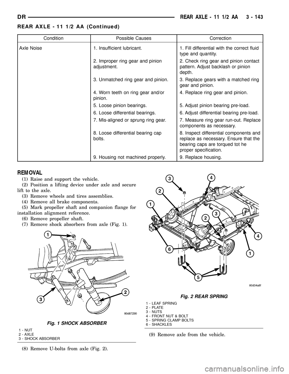
(7) Remove shock absorbers from axle (Fig. 1).
(8) Remove U-bolts from axle (Fig. 2).(9) Remove axle from the vehicle.
Fig. 1 SHOCK ABSORBER
1 - NUT
2 - AXLE
3 - SHOCK ABSORBER
Fig. 2 REAR SPRING
1 - LEAF SPRING
2 - PLATE
3 - NUTS
4 - FRONT NUT & BOLT
5 - SPRING CLAMP BOLTS
6 - SHACKLES
DRREAR AXLE - 11 1/2 AA 3 - 143
REAR AXLE - 11 1/2 AA (Continued)