rear bumper DODGE RAM 1500 1998 2.G Owner's Manual
[x] Cancel search | Manufacturer: DODGE, Model Year: 1998, Model line: RAM 1500, Model: DODGE RAM 1500 1998 2.GPages: 2627
Page 1553 of 2627

SERVICE SLEEVE ASSEMBLY
NOTE: Two sleeve halves are included with each
kit. Modifications as follow, are necessary to create
the correct sleeve assembly for each application.
(1) On 4X2 models, the9lower9sleeve is made by
cutting off the tab and cutting out a notch in the bot-
tom sleeve portion. Round the corners of the cut out
to keep stress cracks from forming. On 4X4 models
the9lower9sleeve is used as provided. (Fig. 15)
(2) On both 4X2 and 4X4 models cut off the front
tab on the upper sleeve portion. (Fig. 16)(3) The sleeve halves are shipped slightly over-
sized to allow custom fitting to each replacement
frame rail tip. It is necessary to grind the mating
surfaces to achieve the desired snug fit into the
replacement tip (rail tube has increasing height rear-
ward of the cut line). Once the two sleeve halves are
fitted, bevel the edges 25É - 30É.
NOTE: Scribing a line 2 mm from the cut edge and
then grinding back to the mark will simplify the
bevel creation process and accuracy.
(4) Remove any burrs at the beveled edges.
(5) Using the Weld Process Specifications table
(Refer to 13 - FRAME & BUMPERS/FRAME - SPEC-
IFICATIONS - WELDING), weld the two halves of
the repair sleeve together. (Fig. 17)
(6) Clean the welds of any flux and other impuri-
ties and grind smooth before proceeding with the
installation of the sleeve.
(7) Find the centerline of the sleeve and scribe a
centerline mark. Mark two additional lines 2 mm
(0.08 in.) on either side of the centerline mark to help
ensure the required 4 mm-6mm(0.16 in. - 0.24 in.)
weld root gap. (Fig. 17)
Fig. 15 4X2 LOWER SLEEVE CUT LOCATION
1 - SERVICE SLEEVE LOWER HALF
2 - CUT DIMENSION 27 mm (1.06 in.)
3 - CUT DIMENSION 36.1 mm (1.42 in)
4 - 4X2 CUTOUT
5 - FRONT TAB CUT LINE (4X2 ONLY)
Fig. 16 UPPER SLEEVE CUT LOCATION
1 - SERVICE SLEEVE UPPER HALF
2 - CUT LOCATION
Fig. 17 SERVICE SLEEVE ASSEMBLY
1 - CENTERLINE SCRIBE MARK
2 - WELD SEAM
3 - REAR TAB (4X4 ONLY)
4 - SCRIBE LINE LOCATION 2 mm (0.08 in.)
5 - FRONT TAB (4X4 ONLY)
13 - 10 FRAMES & BUMPERSDR
FRAME (Continued)
Page 1556 of 2627

STANDARD PROCEDURE - REAR FRAME
H-SECTION REPLACEMENT
CAUTION: This procedure is designed to replace
the H-section/spare tire support located at the rear
of the frame assembly. Prior to any cutting, the
vehicle must be mounted on the appropriate frame
repair equipment (ªframe rackº), checked with three
dimensional measuring equipment, and the neces-
sary pull corrections made. If damage remains in
the frame beyond the area covered by this service
part after the pull, the frame must be replaced in its
entirety.
(1) Before proceding with this repair procedure
review the required service warnings and precau-
tions. (Refer to 13 - FRAME & BUMPERS/FRAME -
WARNING)
(2) Disconnect and isolate the battery negative
cable.
(3) Remove the cargo box. (Refer to 23 - BODY/EX-
TERIOR/CARGO BOX - REMOVAL)
(4) Remove the trailer hitch. (Refer to 13 - FRAME
& BUMPERS/FRAME/TRAILER HITCH -
REMOVAL)
(5) Raise and support the frame so the tires are off
floor.(6) Remove the shock absorbers. (Refer to 2 - SUS-
PENSION/REAR/SHOCK - REMOVAL)
(7) Remove the rear leaf spring shackle bolts and
let the axle rest on the ground. (Fig. 20)
(8) Remove the spare wheel.
Fig. 19 ENGINE COMPARTMENT/FRONT STRUCTURE
Fig. 20 REAR SPRING
1 - SPRING SHACKLE
2 - LEAF SPRING EYE BOLT/NUT
3 - REAR LEAF SPRING
DRFRAMES & BUMPERS 13 - 13
FRAME (Continued)
Page 1557 of 2627

(9) Remove the clip and remove the spare tire
winch tube. (Fig. 21)
(10) Remove the bolts and remove the spare tire
winch. (Fig. 22)
(11) Position the wire harness forward of the work
area.
CAUTION: Do not use any flame or plasma cutting
equipment to cut the frame in this procedure. The
inaccurate and high temperatures achieved during
flame or plasma cutting will change the metal char-
acteristics and may weaken the frame and/or repair
location.(12) Carefully remove the H-section welds using a
grinder or equivalent tool.
(13) Remove the H-section and clean any remain-
ing welds from the frame.
(14) Trial fit the replacement part.
(15) Remove all e-coat from within 25 mm (1.0 in.)
of the weld area.
(16) Using the appropriate measuring equipment,
position the replacement part and verify correct posi-
tioning in all three (X,Y, and Z) planes of space.
(Refer to 13 - FRAME & BUMPERS/FRAME - SPEC-
IFICATIONS - FRAME DIMENSIONS)
CAUTION: Shield the surrounding area and compo-
nents from exposure to the welding spatter and
heat.
(17) Weld the replacement H-section into position.
The welding should be performed in a skip (stitch)
type method to minimize the heat buildup following
I-CAR or the American Welding Society welding pro-
cedures and utilizing the process specifications at the
end of this section. (Refer to 13 - FRAME &
BUMPERS/FRAME - SPECIFICATIONS - WELD-
ING)
(18) Dress the welded area and apply corrosion
resistant coatings inside and out.
(a) Inside the rail, inject a creeping wax based
rust inhibitor compound through the existing holes
in the frame ensuring 100% coverage including the
mating face between the frame and replacement
H-section.
(b) Apply a durable top coat to the outside of the
repair area.
(19) Position the wiring harness back.
CAUTION: Inspect the tire winch assembly for dam-
age. If any one or more of the following are evident,
replace the winch assembly.
²Indications of cracked or bulging plastic.
²Housing flanges are bent or cracked.
²If winch was loose before repair.
(20) Install the spare tire winch and install the
bolts. (Fig. 22)
(21) Tighten the bolts to 41 N´m (30 ft. lbs.).
(22) Install the spare tire winch tube and install
the clip. (Fig. 21)
(23) Install the spare tire.
CAUTION: Check operation of the spare tire winch
by manipulating it up and down. If the winch binds
or jambs, replace the winch assembly.
(24) Lift the axle into position and install the rear
shackle bolts. (Fig. 20)
(25) Tighten the bolts to 163 N´m (120 ft. lbs.).
Fig. 21 SPARE TIRE WINCH TUBE
1 - SPARE TIRE WINCH ASSEMBLY
2 - HAIR PIN CLIP
3 - WINCH TUBE
4 - H-SECTION/SPARE WHEEL SUPPORT
Fig. 22 SPARE TIRE WINCH ASSEMBLY
1 - SPARE TIRE WINCH ASSEMBLY
2 - BOLTS
3 - RETAINER BRACKET
4 - H-SECTION/SPARE WHEEL SUPPORT
13 - 14 FRAMES & BUMPERSDR
FRAME (Continued)
Page 1558 of 2627

(26) Install the lower shock absorber bolts. (Refer
to 2 - SUSPENSION/REAR/SHOCK - INSTALLA-
TION)
(27) Install the trailer hitch. (Refer to 13 - FRAME
& BUMPERS/FRAME/TRAILER HITCH - INSTAL-
LATION)(28) Install the cargo box. (Refer to 23 - BODY/EX-
TERIOR/CARGO BOX - INSTALLATION)
(29) Reconnect the battery ground.
SPECIFICATIONS
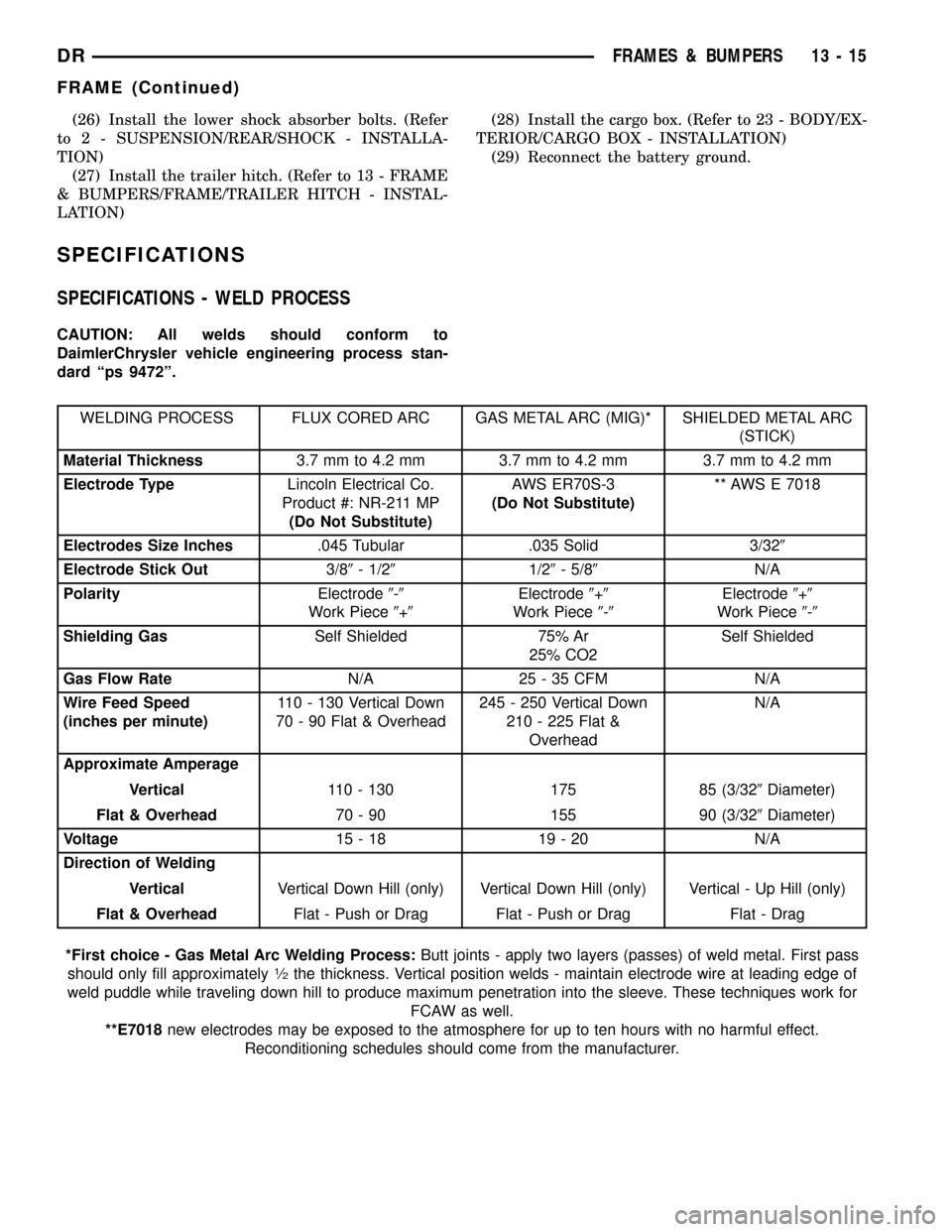
SPECIFICATIONS - WELD PROCESS
CAUTION: All welds should conform to
DaimlerChrysler vehicle engineering process stan-
dard ªps 9472º.
WELDING PROCESS FLUX CORED ARC GAS METAL ARC (MIG)* SHIELDED METAL ARC
(STICK)
Material Thickness3.7 mm to 4.2 mm 3.7 mm to 4.2 mm 3.7 mm to 4.2 mm
Electrode TypeLincoln Electrical Co.
Product #: NR-211 MP
(Do Not Substitute)AWS ER70S-3
(Do Not Substitute)** AWS E 7018
Electrodes Size Inches.045 Tubular .035 Solid 3/329
Electrode Stick Out3/89- 1/291/29- 5/89N/A
PolarityElectrode9-9
Work Piece9+9Electrode9+9
Work Piece9-9Electrode9+9
Work Piece9-9
Shielding GasSelf Shielded 75% Ar
25% CO2Self Shielded
Gas Flow RateN/A 25 - 35 CFM N/A
Wire Feed Speed
(inches per minute)110 - 130 Vertical Down
70 - 90 Flat & Overhead245 - 250 Vertical Down
210 - 225 Flat &
OverheadN/A
Approximate Amperage
Vertical110 - 130 175 85 (3/329Diameter)
Flat & Overhead70 - 90 155 90 (3/329Diameter)
Voltage15-18 19-20 N/A
Direction of Welding
VerticalVertical Down Hill (only) Vertical Down Hill (only) Vertical - Up Hill (only)
Flat & OverheadFlat - Push or Drag Flat - Push or Drag Flat - Drag
*First choice - Gas Metal Arc Welding Process:Butt joints - apply two layers (passes) of weld metal. First pass
should only fill approximately
1¤2the thickness. Vertical position welds - maintain electrode wire at leading edge of
weld puddle while traveling down hill to produce maximum penetration into the sleeve. These techniques work for
FCAW as well.
**E7018new electrodes may be exposed to the atmosphere for up to ten hours with no harmful effect.
Reconditioning schedules should come from the manufacturer.
DRFRAMES & BUMPERS 13 - 15
FRAME (Continued)
Page 1565 of 2627

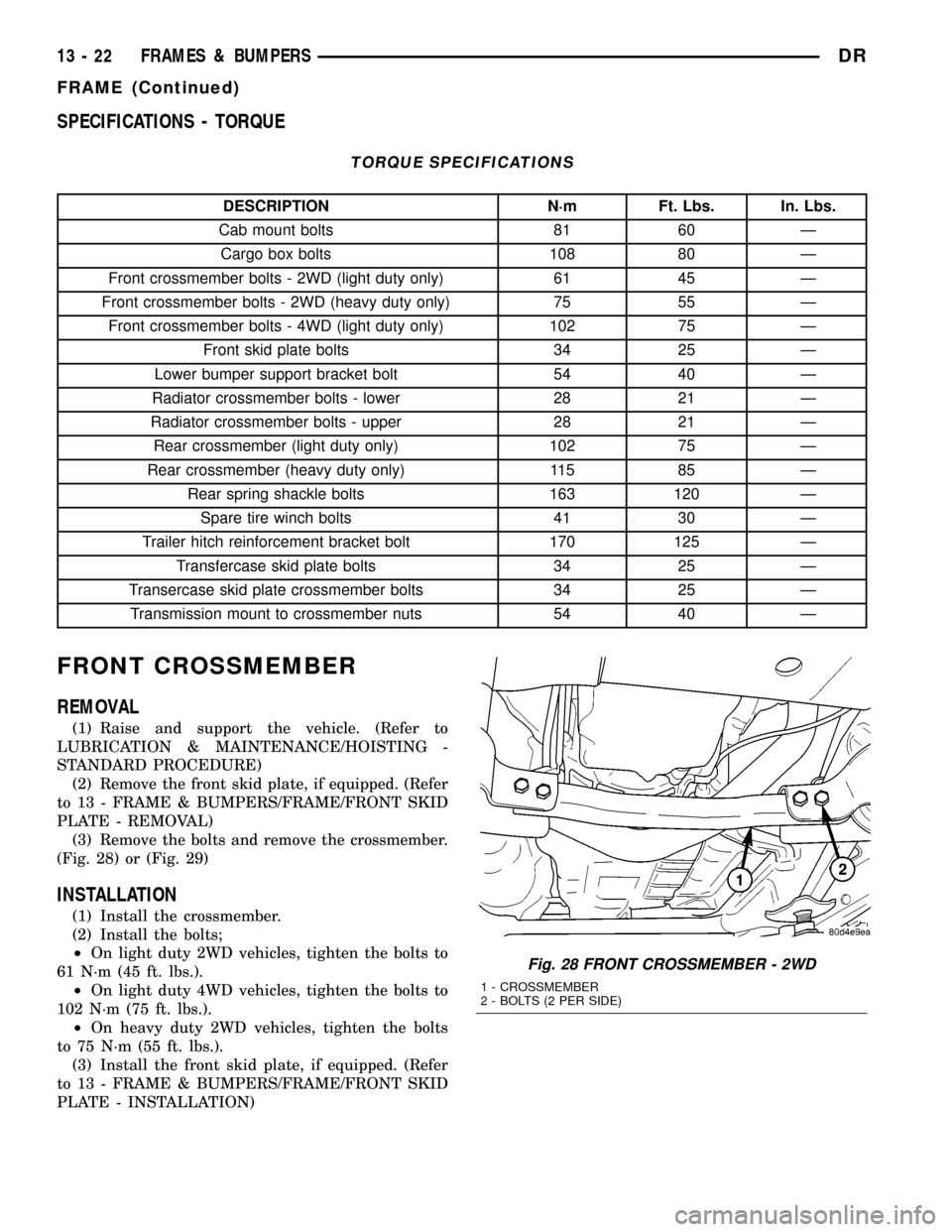
SPECIFICATIONS - TORQUE
TORQUE SPECIFICATIONS
DESCRIPTION N´m Ft. Lbs. In. Lbs.
Cab mount bolts 81 60 Ð
Cargo box bolts 108 80 Ð
Front crossmember bolts - 2WD (light duty only) 61 45 Ð
Front crossmember bolts - 2WD (heavy duty only) 75 55 Ð
Front crossmember bolts - 4WD (light duty only) 102 75 Ð
Front skid plate bolts 34 25 Ð
Lower bumper support bracket bolt 54 40 Ð
Radiator crossmember bolts - lower 28 21 Ð
Radiator crossmember bolts - upper 28 21 Ð
Rear crossmember (light duty only) 102 75 Ð
Rear crossmember (heavy duty only) 115 85 Ð
Rear spring shackle bolts 163 120 Ð
Spare tire winch bolts 41 30 Ð
Trailer hitch reinforcement bracket bolt 170 125 Ð
Transfercase skid plate bolts 34 25 Ð
Transercase skid plate crossmember bolts 34 25 Ð
Transmission mount to crossmember nuts 54 40 Ð
FRONT CROSSMEMBER
REMOVAL
(1) Raise and support the vehicle. (Refer to
LUBRICATION & MAINTENANCE/HOISTING -
STANDARD PROCEDURE)
(2) Remove the front skid plate, if equipped. (Refer
to 13 - FRAME & BUMPERS/FRAME/FRONT SKID
PLATE - REMOVAL)
(3) Remove the bolts and remove the crossmember.
(Fig. 28) or (Fig. 29)
INSTALLATION
(1) Install the crossmember.
(2) Install the bolts;
²On light duty 2WD vehicles, tighten the bolts to
61 N´m (45 ft. lbs.).
²On light duty 4WD vehicles, tighten the bolts to
102 N´m (75 ft. lbs.).
²On heavy duty 2WD vehicles, tighten the bolts
to 75 N´m (55 ft. lbs.).
(3) Install the front skid plate, if equipped. (Refer
to 13 - FRAME & BUMPERS/FRAME/FRONT SKID
PLATE - INSTALLATION)
Fig. 28 FRONT CROSSMEMBER - 2WD
1 - CROSSMEMBER
2 - BOLTS (2 PER SIDE)
13 - 22 FRAMES & BUMPERSDR
FRAME (Continued)
Page 1566 of 2627

FRONT SKID PLATE
REMOVAL
(1) Raise and support the vehicle. (Refer to
LUBRICATION & MAINTENANCE/HOISTING -
STANDARD PROCEDURE)
(2) Remove the bolts. (Fig. 30)
(3) Slide skid plate back off of the crossmember
and remove.
INSTALLATION
(1) Snap the rear tabs over the front crossmember
and install the skid plate.
(2) Install the bolts and tighten to 34 N´m (25 ft.
lbs.).
FRONT TOW HOOK ASSEMBLY
REMOVAL
(1) Remove front bumper. (Refer to 13 - FRAME &
BUMPERS/BUMPERS/FRONT BUMPER -
REMOVAL)
(2) Remove the bolts and remove the tow hook
assembly. (Fig. 31) and (Fig. 32)
INSTALLATION
(1) Install the tow hook assembly and bolts hand
tight.
(2) Install the front bumper. (Refer to 13 - FRAME
& BUMPERS/BUMPERS/FRONT BUMPER -
INSTALLATION)
(3) Tighten the tow hook bolts to 68 N´m (50 ft.
lbs.).
Fig. 29 FRONT CROSSMEMBER - 4WD
1 - BOLTS (2 PER SIDE)
2 - CROSSMEMBER
Fig. 30 FRONT SKID PLATE
1 - FRONT CROSSMEMBER
2 - FRONT SKID PLATE
3 - BOLTS (2)
Fig. 31 FRONT TOW HOOK ASSEMBLY
1 - BUMPER CENTER SUPPORT BRACKET
2 - BOLTS (6)
3 - TOW HOOK ASSEMBLY
DRFRAMES & BUMPERS 13 - 23
FRONT CROSSMEMBER (Continued)
Page 1567 of 2627

TRANSMISSION
CROSSMEMBER
REMOVAL
(1) Raise and support the vehicle. (Refer to
LUBRICATION & MAINTENANCE/HOISTING -
STANDARD PROCEDURE)
(2) Remove the transfercase skid plate, if
equipped. (Refer to 13 - FRAME & BUMPERS/
FRAME/TRANSFER CASE SKID PLATE -
REMOVAL)
(3) Support the transmission with a suitable lifting
device.
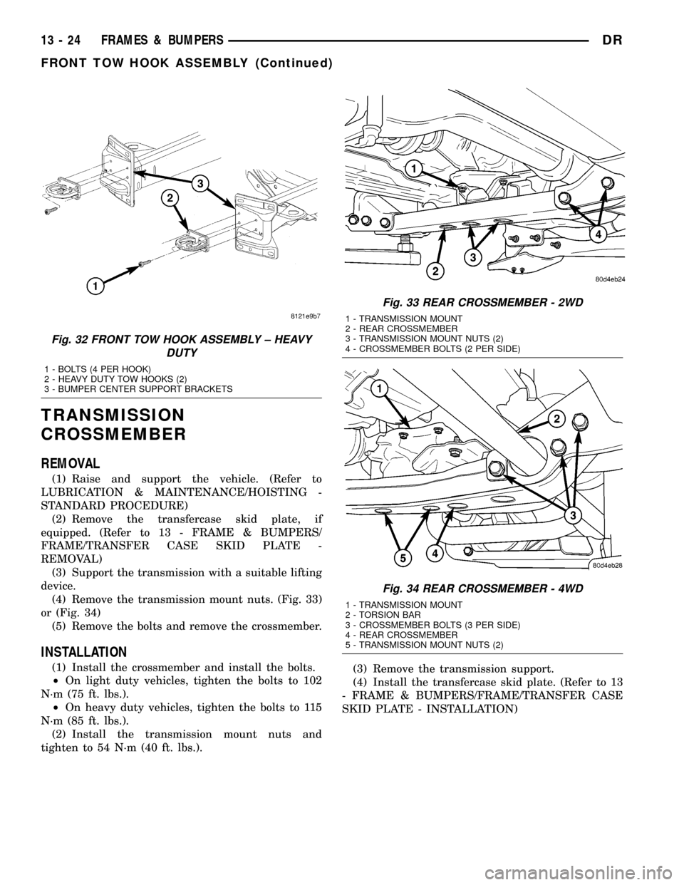
(4) Remove the transmission mount nuts. (Fig. 33)
or (Fig. 34)
(5) Remove the bolts and remove the crossmember.
INSTALLATION
(1) Install the crossmember and install the bolts.
²On light duty vehicles, tighten the bolts to 102
N´m (75 ft. lbs.).
²On heavy duty vehicles, tighten the bolts to 115
N´m (85 ft. lbs.).
(2) Install the transmission mount nuts and
tighten to 54 N´m (40 ft. lbs.).(3) Remove the transmission support.
(4) Install the transfercase skid plate. (Refer to 13
- FRAME & BUMPERS/FRAME/TRANSFER CASE
SKID PLATE - INSTALLATION)
Fig. 32 FRONT TOW HOOK ASSEMBLY ± HEAVY
DUTY
1 - BOLTS (4 PER HOOK)
2 - HEAVY DUTY TOW HOOKS (2)
3 - BUMPER CENTER SUPPORT BRACKETS
Fig. 33 REAR CROSSMEMBER - 2WD
1 - TRANSMISSION MOUNT
2 - REAR CROSSMEMBER
3 - TRANSMISSION MOUNT NUTS (2)
4 - CROSSMEMBER BOLTS (2 PER SIDE)
Fig. 34 REAR CROSSMEMBER - 4WD
1 - TRANSMISSION MOUNT
2 - TORSION BAR
3 - CROSSMEMBER BOLTS (3 PER SIDE)
4 - REAR CROSSMEMBER
5 - TRANSMISSION MOUNT NUTS (2)
13 - 24 FRAMES & BUMPERSDR
FRONT TOW HOOK ASSEMBLY (Continued)
Page 1568 of 2627

TRAILER HITCH
REMOVAL
(1) Remove the rear bumper. (Refer to 13 -
FRAME & BUMPERS/BUMPERS/REAR BUMPER -
REMOVAL)
(2) Remove the hitch bolts. (Fig. 35) and (Fig. 36)
(3) Disconnect all wire harness support push pins.
(4) Remove the rear two cargo box bolts and loosen
the remaining bolts. (Refer to 23 - BODY/EXTERI-
OR/CARGO BOX - REMOVAL)
(5) Using a suitable lifting device, lift and support
the rear of the cargo box and remove the hitch.
INSTALLATION
(1) Install the hitch onto the frame rails and make
sure the locators on the inside of the hitch brackets
are engaged with the holes in the top of the frame
rails properly.
(2) Lower the cargo box and install the rear bolts.
(Refer to 23 - BODY/EXTERIOR/CARGO BOX -
INSTALLATION)
(3) Install the hitch bolts and tighten to 170 N´m
(125 ft. lbs.).
(4) Connect all wire harness support push pins.
(5) Install the rear bumper. (Refer to 13 - FRAME
& BUMPERS/BUMPERS/REAR BUMPER - INSTAL-
LATION)
Fig. 35 TRAILER HITCH ± LIGHT DUTY
1 - LOCATING TAB HOLE
2 - LOCATING PIN HOLE
3 - U-NUTS (2)
4 - BUMPER SUPPORT BRACKETS5 - HITCH
6 - BUMPER BRACKET BOLTS (4)
7 - HITCH BOLTS (4)
DRFRAMES & BUMPERS 13 - 25
Page 2021 of 2627

is applied. The clutch application can also be felt by
touching the appropriate element while applying air
pressure. As the air pressure is released, the clutch
should also release.
DIAGNOSIS AND TESTING - CONVERTER
HOUSING FLUID LEAK
When diagnosing converter housing fluid leaks,
two items must be established before repair.
(1) Verify that a leak condition actually exists.
(2) Determined the true source of the leak.
Some suspected converter housing fluid leaks may
not be leaks at all. They may only be the result of
residual fluid in the converter housing, or excess
fluid spilled during factory fill or fill after repair.
Converter housing leaks have several potential
sources. Through careful observation, a leak source
can be identified before removing the transmission
for repair. Torque converter seal leaks tend to move
along the drive hub and onto the rear of the con-
verter. Pump cover seal tend to run down the cover
and the inside surface of the bellhousing.
Some leaks, or suspected leaks, may be particu-
larly difficult to locate. If necessary, a Mopart
approved dye may be used to locate a leak.
TORQUE CONVERTER LEAK POINTS
Possible sources of converter leaks are:
(1) Leaks at the weld joint around the outside
diameter weld (Fig. 7).
(2) Leaks at the converter hub weld (Fig. 7).
STANDARD PROCEDURE - ALUMINUM
THREAD REPAIR
Damaged or worn threads in the aluminum trans-
mission case and valve body can be repaired by the
use of Heli-CoilsŸ, or equivalent. This repair con-
sists of drilling out the worn-out damaged threads.
Then tap the hole with a special Heli-CoilŸ tap, or
equivalent, and installing a Heli-CoilŸ insert, or
equivalent, into the hole. This brings the hole back to
its original thread size.
Heli-CoilŸ, or equivalent, tools and inserts are
readily available from most automotive parts suppli-
ers.
REMOVAL
(1) Disconnect the negative battery cable.
(2) Raise and support the vehicle
(3) Remove any necessary skid plates. (Refer to 13
- FRAMES & BUMPERS/FRAME/TRANSFER CASE
SKID PLATE - REMOVAL)
(4) Mark propeller shaft and axle companion
flanges for assembly alignment.
(5) Remove the rear propeller shaft
(6) Remove the front propeller shaft, if necessary.
(7) Remove the engine to transmission collar (Fig.
8).
(8) Remove the exhaust support bracket from the
rear of the transmission.
(9) Disconnect and lower or remove any necessary
exhaust components.
Fig. 7 Torque Converter Assembly
1 - TURBINE ASSEMBLY
2-STATOR
3 - CONVERTER HUB
4 - O-RING
5 - IMPELLER ASSEMBLY
6 - CONVERTER CLUTCH PISTON
7 - TURBINE HUB
Fig. 8 Transmission Collar
1 - ENGINE
2 - STRUCTURAL DUST COVER
3 - TRANSMISSION
21 - 318 AUTOMATIC TRANSMISSION - 45RFE/545RFEDR
AUTOMATIC TRANSMISSION - 45RFE/545RFE (Continued)
Page 2120 of 2627

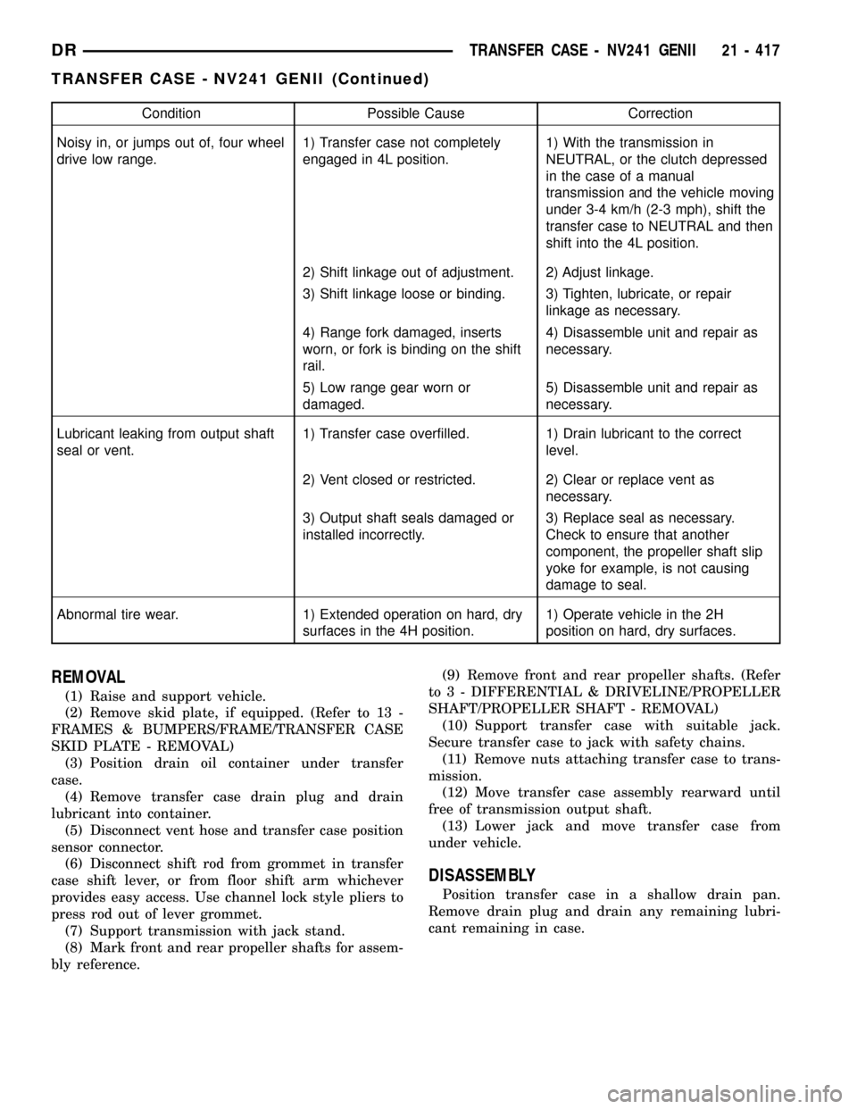
Condition Possible Cause Correction
Noisy in, or jumps out of, four wheel
drive low range.1) Transfer case not completely
engaged in 4L position.1) With the transmission in
NEUTRAL, or the clutch depressed
in the case of a manual
transmission and the vehicle moving
under 3-4 km/h (2-3 mph), shift the
transfer case to NEUTRAL and then
shift into the 4L position.
2) Shift linkage out of adjustment. 2) Adjust linkage.
3) Shift linkage loose or binding. 3) Tighten, lubricate, or repair
linkage as necessary.
4) Range fork damaged, inserts
worn, or fork is binding on the shift
rail.4) Disassemble unit and repair as
necessary.
5) Low range gear worn or
damaged.5) Disassemble unit and repair as
necessary.
Lubricant leaking from output shaft
seal or vent.1) Transfer case overfilled. 1) Drain lubricant to the correct
level.
2) Vent closed or restricted. 2) Clear or replace vent as
necessary.
3) Output shaft seals damaged or
installed incorrectly.3) Replace seal as necessary.
Check to ensure that another
component, the propeller shaft slip
yoke for example, is not causing
damage to seal.
Abnormal tire wear. 1) Extended operation on hard, dry
surfaces in the 4H position.1) Operate vehicle in the 2H
position on hard, dry surfaces.
REMOVAL
(1) Raise and support vehicle.
(2) Remove skid plate, if equipped. (Refer to 13 -
FRAMES & BUMPERS/FRAME/TRANSFER CASE
SKID PLATE - REMOVAL)
(3) Position drain oil container under transfer
case.
(4) Remove transfer case drain plug and drain
lubricant into container.
(5) Disconnect vent hose and transfer case position
sensor connector.
(6) Disconnect shift rod from grommet in transfer
case shift lever, or from floor shift arm whichever
provides easy access. Use channel lock style pliers to
press rod out of lever grommet.
(7) Support transmission with jack stand.
(8) Mark front and rear propeller shafts for assem-
bly reference.(9) Remove front and rear propeller shafts. (Refer
to 3 - DIFFERENTIAL & DRIVELINE/PROPELLER
SHAFT/PROPELLER SHAFT - REMOVAL)
(10) Support transfer case with suitable jack.
Secure transfer case to jack with safety chains.
(11) Remove nuts attaching transfer case to trans-
mission.
(12) Move transfer case assembly rearward until
free of transmission output shaft.
(13) Lower jack and move transfer case from
under vehicle.
DISASSEMBLY
Position transfer case in a shallow drain pan.
Remove drain plug and drain any remaining lubri-
cant remaining in case.
DRTRANSFER CASE - NV241 GENII 21 - 417
TRANSFER CASE - NV241 GENII (Continued)