rear bumper DODGE RAM 1500 1998 2.G Workshop Manual
[x] Cancel search | Manufacturer: DODGE, Model Year: 1998, Model line: RAM 1500, Model: DODGE RAM 1500 1998 2.GPages: 2627
Page 1 of 2627
GROUP TAB LOCATOR
Introduction
0Lubrication & Maintenance
2Suspension
3Differential & Driveline
5Brakes
6Clutch
7Cooling
8AAudio/Video
8BChime/Buzzer
8EElectronic Control Modules
8FEngine Systems
8GHeated Systems
8HHorn
8IIgnition Control
8JInstrument Cluster
8LLamps
8MMessage Systems
8NPower Systems
8ORestraints
8PSpeed Control
8QVehicle Theft Security
8RWipers/Washers
8TNavigation/Telecommunication
8WWiring
9Engine
11Exhaust System
13Frame & Bumpers
14Fuel System
19Steering
21Transmission and Transfer Case
22Tires/Wheels
23Body
24Heating & Air Conditioning
25Emissions Control
Component and System Index
Service Manual Comment Forms (Rear of Manual)
Page 40 of 2627
angle while adjusting caster, move one pivot bolt of
the upper control arm in or out. Then move the other
pivot bolt of the upper control arm in the opposite
direction. Install special tool 8876 between the top of
the upper control arm bracket and the upper control
arm (on 1500 series 4X2 & 4X4). Install special tool
8876 between the bottom of the upper control arm
bracket pressing the tool against the frame and the
upper control arm (on 2500/3500 series 4X2) in order
to move the upper control arm outwards for proper
adjustment with the vehicle at normal ride height
(Fig. 3).
To increase positive caster angle, move the rear
position of the upper control arm inward (toward the
engine). Move the front of the upper control arm out-
ward (away from the engine) slightly until the origi-
nal camber angle is obtained using special tool 8876
to move the upper control arm for proper adjustment.
(Fig. 3)
CAMBER
Move both pivot bolts of the upper control arm
together in or out. This will change the camber angle
significantly and little effect on the caster angle
using special tool 8876 to move the upper control
arm for proper adjustment. (Fig. 3)
After adjustment is made tighten the upper control
arm nuts to proper torque specification.
TOE ADJUSTMENT
The wheel toe position adjustment is the final
adjustment.
(1) Start the engine and turn wheels both ways
before straightening the wheels. Secure the steering
wheel with the front wheels in the straight-ahead
position.
(2) Loosen the tie rod jam nuts.
NOTE: Each front wheel should be adjusted for
one-half of the total toe position specification. This
will ensure the steering wheel will be centered
when the wheels are positioned straight-ahead.
(3) Adjust the wheel toe position by turning the
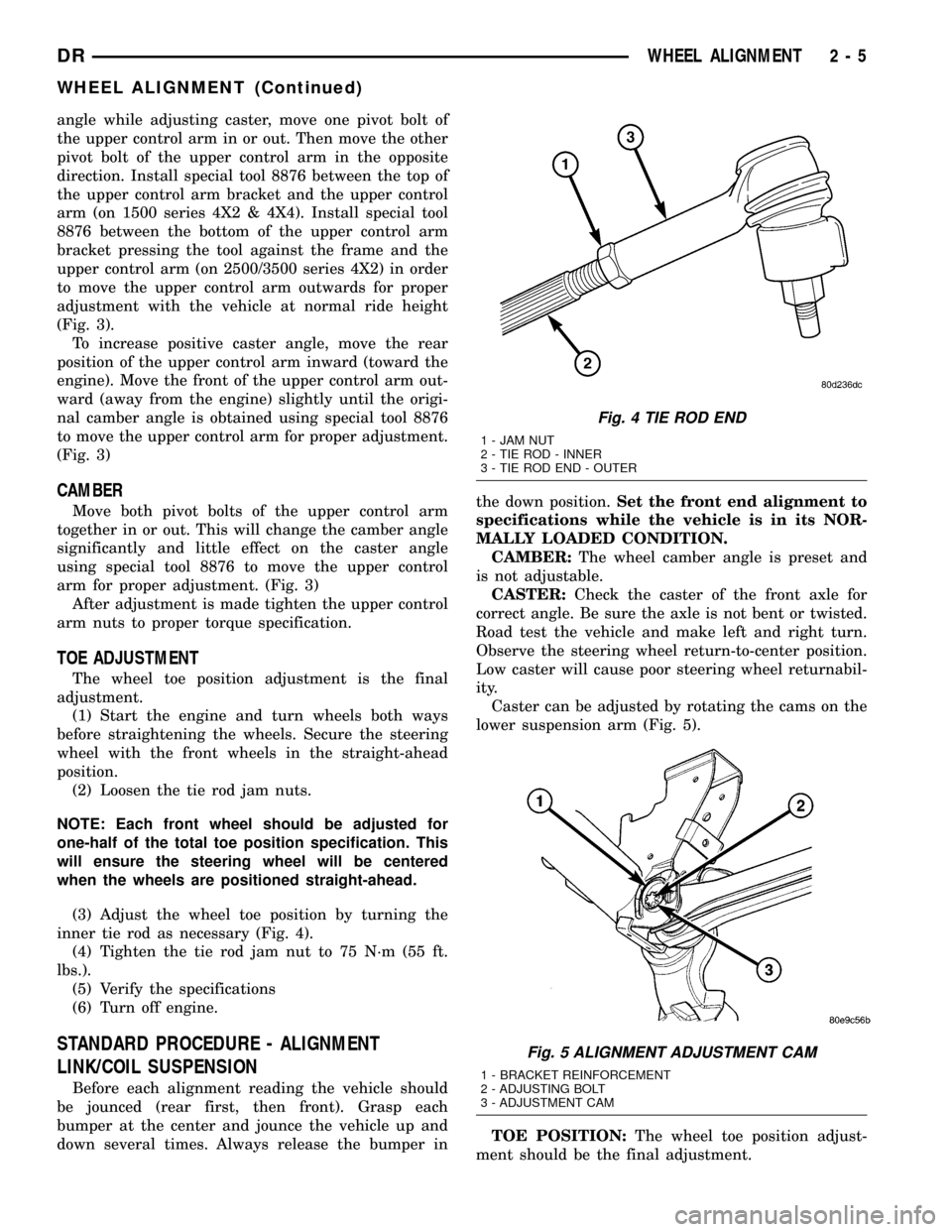
inner tie rod as necessary (Fig. 4).
(4) Tighten the tie rod jam nut to 75 N´m (55 ft.
lbs.).
(5) Verify the specifications
(6) Turn off engine.
STANDARD PROCEDURE - ALIGNMENT
LINK/COIL SUSPENSION
Before each alignment reading the vehicle should
be jounced (rear first, then front). Grasp each
bumper at the center and jounce the vehicle up and
down several times. Always release the bumper inthe down position.Set the front end alignment to
specifications while the vehicle is in its NOR-
MALLY LOADED CONDITION.
CAMBER:The wheel camber angle is preset and
is not adjustable.
CASTER:Check the caster of the front axle for
correct angle. Be sure the axle is not bent or twisted.
Road test the vehicle and make left and right turn.
Observe the steering wheel return-to-center position.
Low caster will cause poor steering wheel returnabil-
ity.
Caster can be adjusted by rotating the cams on the
lower suspension arm (Fig. 5).
TOE POSITION:The wheel toe position adjust-
ment should be the final adjustment.
Fig. 4 TIE ROD END
1 - JAM NUT
2 - TIE ROD - INNER
3 - TIE ROD END - OUTER
Fig. 5 ALIGNMENT ADJUSTMENT CAM
1 - BRACKET REINFORCEMENT
2 - ADJUSTING BOLT
3 - ADJUSTMENT CAM
DRWHEEL ALIGNMENT 2 - 5
WHEEL ALIGNMENT (Continued)
Page 48 of 2627
BUSHINGS
REMOVAL
REMOVAL - LOWER CONTROL ARM
BUSHINGS - 4WD (LD)
(1) Remove the lower control arm (Refer to 2 -
SUSPENSION/FRONT/LOWER CONTROL ARM -
REMOVAL).
(2) Secure the control arm in a vise.
NOTE: Extreme pressure lubrication must be used
on the threaded portions of the tool. This will
increase the longevity of the tool and insure proper
operation during the removal and installation pro-
cess.
FRAME MOUNTED BUSHING
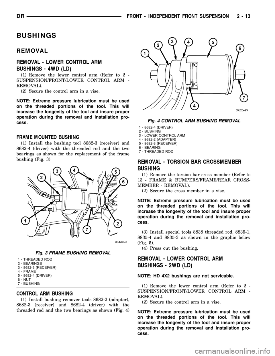
(1) Install the bushing tool 8682-3 (receiver) and
8682-4 (driver) with the threaded rod and the two
bearings as shown for the replacement of the frame
bushing (Fig. 3)
CONTROL ARM BUSHING
(1) Install bushing remover tools 8682-2 (adapter),
8682-3 (receiver) and 8682-4 (driver) with the
threaded rod and the two bearings as shown (Fig. 4)
REMOVAL - TORSION BAR CROSSMEMBER
BUSHING
(1) Remove the torsion bar cross member (Refer to
13 - FRAME & BUMPERS/FRAME/REAR CROSS-
MEMBER - REMOVAL).
(2) Secure the cross member in a vise.
NOTE: Extreme pressure lubrication must be used
on the threaded portions of the tool. This will
increase the longevity of the tool and insure proper
operation during the removal and installation pro-
cess.
(3) Install special tools 8838 threaded rod, 8835-1,
8835-4 and 8835-3 as shown in the graphic below
(Fig. 5).
(4) Press out the bushing.
REMOVAL - LOWER CONTROL ARM
BUSHINGS - 2WD (LD)
NOTE: HD 4X2 bushings are not servicable.
(1) Remove the lower control arm (Refer to 2 -
SUSPENSION/FRONT/LOWER CONTROL ARM -
REMOVAL).
(2) Secure the control arm in a vise.
NOTE: Extreme pressure lubrication must be used
on the threaded portions of the tool. This will
increase the longevity of the tool and insure proper
operation during the removal and installation pro-
cess.
Fig. 3 FRAME BUSHING REMOVAL
1 - THREADED ROD
2 - BEARINGS
3 - 8682-3 (RECEIVER)
4 - FRAME
5 - 8682-4 (DRIVER)
6 - NUT
7 - BUSHING
Fig. 4 CONTROL ARM BUSHING REMOVAL
1 - 8682-4 (DRIVER)
2 - BUSHING
3 - LOWER CONTROL ARM
4 - 8682-2 (ADAPTER)
5 - 8682-3 (RECEIVER)
6 - BEARING
7 - THREADED ROD
DRFRONT - INDEPENDENT FRONT SUSPENSION 2 - 13
Page 50 of 2627
FRAME MOUNTED BUSHING
NOTE: Extreme pressure lubrication must be used
on the threaded portions of the tool. This will
increase the longevity of the tool and insure proper
operation during the removal and installation pro-
cess.
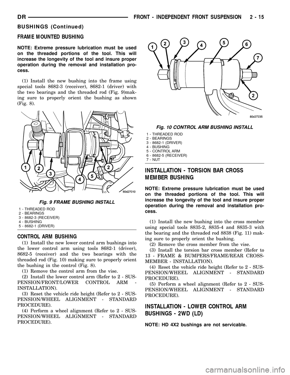
(1) Install the new bushing into the frame using
special tools 8682-3 (receiver), 8682-1 (driver) with
the two bearings and the threaded rod (Fig. 9)mak-
ing sure to properly orient the bushing as shown
(Fig. 8).
CONTROL ARM BUSHING
(1) Install the new lower control arm bushings into
the lower control arm using tools 8682-1 (driver),
8682-5 (receiver) and the two bearings with the
threaded rod (Fig. 10) making sure to properly orient
the bushing in the control (Fig. 8).
(1) Remove the control arm from the vise.
(2) Install the lower control arm (Refer to 2 - SUS-
PENSION/FRONT/LOWER CONTROL ARM -
INSTALLATION).
(3) Reset the vehicle ride height (Refer to 2 - SUS-
PENSION/WHEEL ALIGNMENT - STANDARD
PROCEDURE).
(4) Perform a wheel alignment (Refer to 2 - SUS-
PENSION/WHEEL ALIGNMENT - STANDARD
PROCEDURE).
INSTALLATION - TORSION BAR CROSS
MEMBER BUSHING
NOTE: Extreme pressure lubrication must be used
on the threaded portions of the tool. This will
increase the longevity of the tool and insure proper
operation during the removal and installation pro-
cess.
(1) Install the new bushing into the cross member
using special tools 8835-2, 8835-4 and 8835-3 with
the bearing and the threaded rod 8838 (Fig. 11) mak-
ing sure to properly orient the bushing.
(2) Remove the cross member from the vise.
(3) Install the torsion bar cross member (Refer to
13 - FRAME & BUMPERS/FRAME/REAR CROSS-
MEMBER - INSTALLATION).
(4) Reset the vehicle ride height (Refer to 2 - SUS-
PENSION/WHEEL ALIGNMENT - STANDARD
PROCEDURE).
(5) Perform a wheel alignment (Refer to 2 - SUS-
PENSION/WHEEL ALIGNMENT - STANDARD
PROCEDURE).
INSTALLATION - LOWER CONTROL ARM
BUSHINGS - 2WD (LD)
NOTE: HD 4X2 bushings are not servicable.
Fig. 9 FRAME BUSHING INSTALL
1 - THREADED ROD
2 - BEARINGS
3 - 8682-3 (RECEIVER)
4 - BUSHING
5 - 8682-1 (DRIVER)
Fig. 10 CONTROL ARM BUSHING INSTALL
1 - THREADED ROD
2 - BEARINGS
3 - 8682-1 (DRIVER)
4 - BUSHING
5 - CONTROL ARM
6 - 8682-5 (RECEIVER)
7 - NUT
DRFRONT - INDEPENDENT FRONT SUSPENSION 2 - 15
BUSHINGS (Continued)
Page 61 of 2627
INSTALLATION
INSTALLATION - 4X4
(1) Install the stabilizer link to the vehicle.
(2) Install the lower nut and Tighten to 102 N´m
(75 ft. lbs.).
(3) Install the retainers, grommets and upper nut
and Tighten to 38 N´m (27 ft. lbs.).
(4) Remove the support and lower the vehicle.
INSTALLATION - 4X2
(1) Install the stabilizer link to the vehicle (Fig.
29).
(2) Install the lower nut and Tighten to 102 N´m
(75 ft. lbs.).
(3) Install the retainers, grommets and upper nut
and Tighten to 38 N´m (27 ft. lbs.).
(4) Remove the support and lower the vehicle.
TORSION BAR
DESCRIPTION
The front of the bar connects to the back side of
the lower suspension arm. The rear end of the bar is
mounted in a anchor that rests in the frame cross-
member.
OPERATION
The torsion bars are used to control ride height
and ride quality. The vehicle height is adjusted
through an anchor adjustment bolt that increases or
decreases the wind up of the torsion bar. Increasing
or decreasing the bar angle changes the wind up of
the suspension arms.
REMOVAL
CAUTION: The left and right side torsion bars are
NOT interchangeable. The bars are identified and
stamped R or L, for right or left. The bars do not
have a front or rear end and can be installed with
either end facing forward.
(1) Raise and support the vehicle with the front
suspension hanging.
(2) Remove the transfer case skid plate (Refer to
13 - FRAME & BUMPERS/FRAME/TRANSFER
CASE SKID PLATE - REMOVAL).
NOTE: Count and record the number of turns for
installation reference.
(3) Mark the adjustment bolt setting.
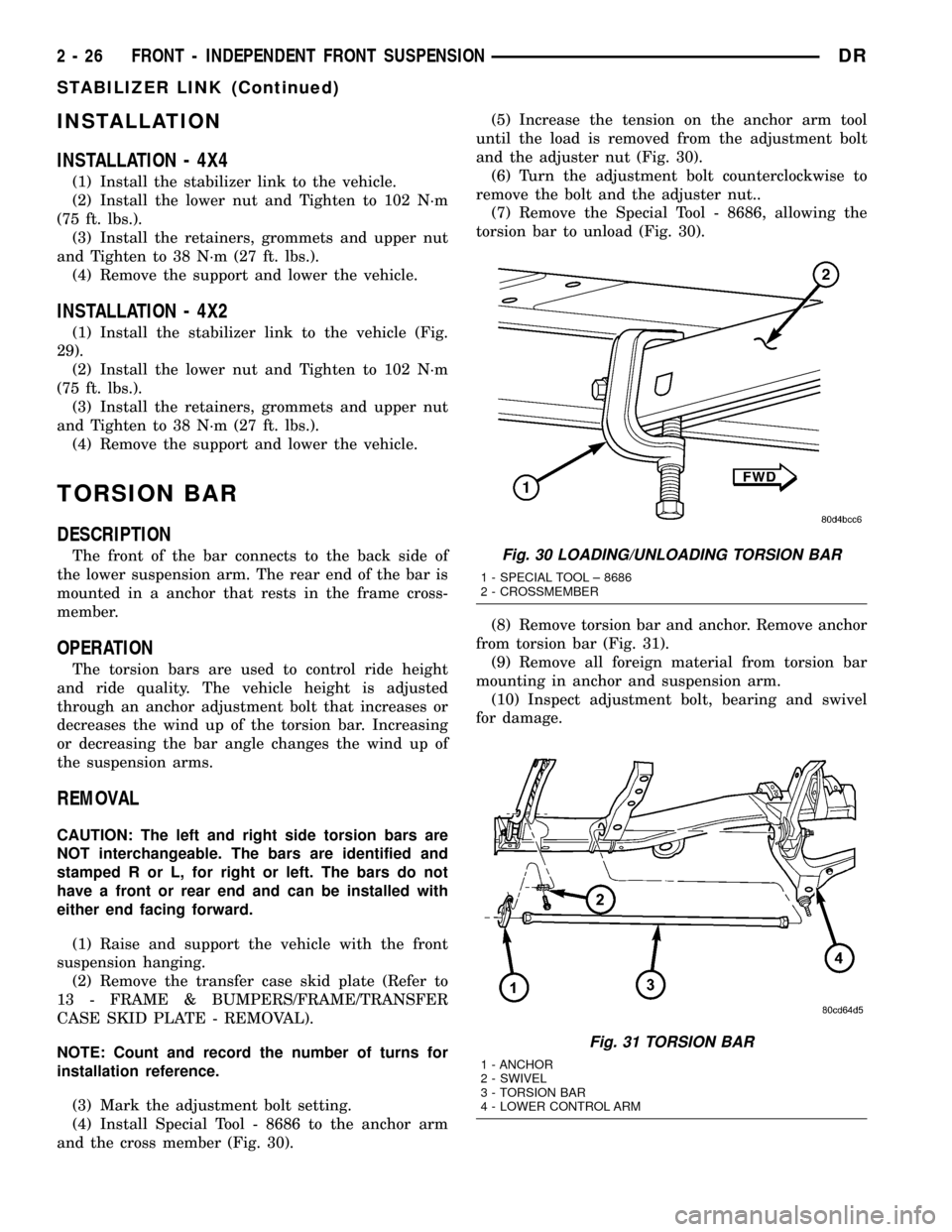
(4) Install Special Tool - 8686 to the anchor arm
and the cross member (Fig. 30).(5) Increase the tension on the anchor arm tool
until the load is removed from the adjustment bolt
and the adjuster nut (Fig. 30).
(6) Turn the adjustment bolt counterclockwise to
remove the bolt and the adjuster nut..
(7) Remove the Special Tool - 8686, allowing the
torsion bar to unload (Fig. 30).
(8) Remove torsion bar and anchor. Remove anchor
from torsion bar (Fig. 31).
(9) Remove all foreign material from torsion bar
mounting in anchor and suspension arm.
(10) Inspect adjustment bolt, bearing and swivel
for damage.
Fig. 30 LOADING/UNLOADING TORSION BAR
1 - SPECIAL TOOL ± 8686
2 - CROSSMEMBER
Fig. 31 TORSION BAR
1 - ANCHOR
2 - SWIVEL
3 - TORSION BAR
4 - LOWER CONTROL ARM
2 - 26 FRONT - INDEPENDENT FRONT SUSPENSIONDR
STABILIZER LINK (Continued)
Page 62 of 2627
INSTALLATION
CAUTION: The left and right side torsion bars are
NOT interchangeable. The bars are identified and
stamped R or L, for right or left. The bars do not
have a front or rear end and can be installed with
either end facing forward.
(1) Insert torsion bar ends into anchor and suspen-
sion arm.
(2) Position the anchor in the frame crossmember.
(3) Install Special Tool - 8686 to the anchor and
the crossmember (Fig. 30).
(4) Increase the tension on the anchor in order to
load the torsion bar.
(5) Install the adjustment bolt and the adjuster
nut.
(6) Turn adjustment bolt clockwise the recorded
amount of turns.
(7) Remove tool - 8686 from the torsion bar cross-
member (Fig. 30).
(8) Install the transfer case skid plate (Refer to 13
- FRAME & BUMPERS/FRAME/TRANSFER CASE
SKID PLATE - INSTALLATION).
(9) Lower vehicle and adjust the front suspension
height (Refer to 2 - SUSPENSION/WHEEL ALIGN-
MENT - STANDARD PROCEDURE).
(10) Perform a wheel alignment (Refer to 2 - SUS-
PENSION/WHEEL ALIGNMENT - STANDARD
PROCEDURE).
UPPER BALL JOINT
DIAGNOSIS AND TESTING - UPPER BALL
JOINT
NOTE: If the ball joint is equipped with a lubrication
fitting, grease the joint then road test the vehicle
before performing test.
(1) Raise the front of the vehicle. Place safety floor
stands under both lower control arms as far outboard
as possible. Lower the vehicle to allow the stands to
support some or all of the vehicle weight.
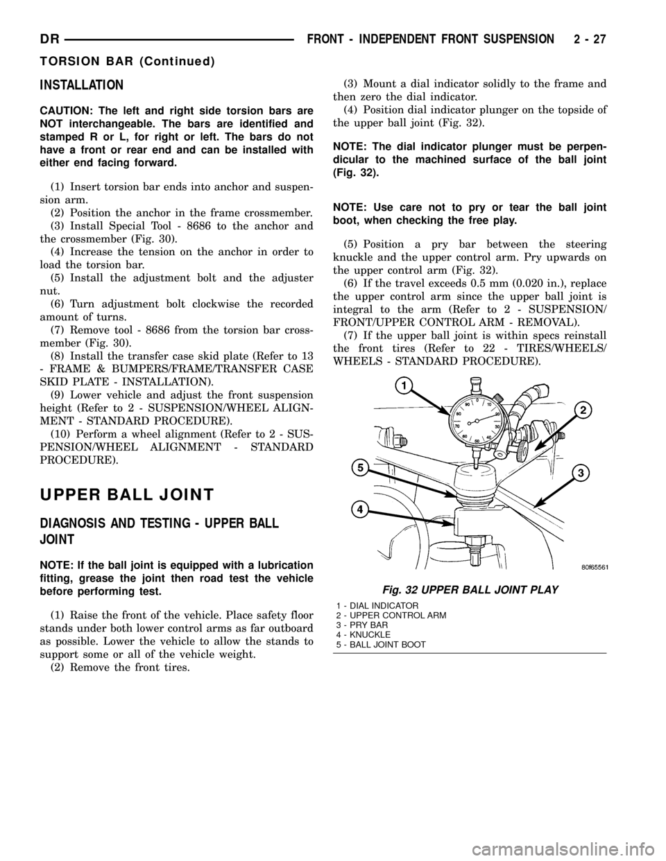
(2) Remove the front tires.(3) Mount a dial indicator solidly to the frame and
then zero the dial indicator.
(4) Position dial indicator plunger on the topside of
the upper ball joint (Fig. 32).
NOTE: The dial indicator plunger must be perpen-
dicular to the machined surface of the ball joint
(Fig. 32).
NOTE: Use care not to pry or tear the ball joint
boot, when checking the free play.
(5) Position a pry bar between the steering
knuckle and the upper control arm. Pry upwards on
the upper control arm (Fig. 32).
(6) If the travel exceeds 0.5 mm (0.020 in.), replace
the upper control arm since the upper ball joint is
integral to the arm (Refer to 2 - SUSPENSION/
FRONT/UPPER CONTROL ARM - REMOVAL).
(7) If the upper ball joint is within specs reinstall
the front tires (Refer to 22 - TIRES/WHEELS/
WHEELS - STANDARD PROCEDURE).
Fig. 32 UPPER BALL JOINT PLAY
1 - DIAL INDICATOR
2 - UPPER CONTROL ARM
3-PRYBAR
4 - KNUCKLE
5 - BALL JOINT BOOT
DRFRONT - INDEPENDENT FRONT SUSPENSION 2 - 27
TORSION BAR (Continued)
Page 76 of 2627
REAR
TABLE OF CONTENTS
page page
REAR
DESCRIPTION.........................41
DIAGNOSIS AND TESTING - SPRING AND
SHOCK.............................41
SPECIFICATIONS
TORQUE CHART......................42
BUSHINGS
REMOVAL.............................43
INSTALLATION.........................43
JOUNCE BUMPER
REMOVAL.............................43
INSTALLATION.........................43
AUXILIARY SPRING BUMPERS (3500)
REMOVAL.............................43INSTALLATION.........................43
SHOCK
REMOVAL.............................43
INSTALLATION.........................43
SPRING
DESCRIPTION.........................44
OPERATION...........................44
REMOVAL.............................44
INSTALLATION.........................44
SPRING TIP INSERTS
REMOVAL.............................44
INSTALLATION.........................45
REAR
DESCRIPTION
The rear suspension is comprised of:
²Shock Absorbers
²Jounce Bumpers
²Leaf Springs
²Auxiliary Leaf Spring (3500 series)
²Auxiliary Spring Bumpers (3500 series)
²Drive Axle
CAUTION: A vehicle should always be loaded so
the vehicle weight center-line is located immedi-
ately forward of the rear axle. Correct vehicle load-
ing provides proper front tire-to-road contact. This
results in maximum vehicle handling stability and
safety. Incorrect vehicle weight distribution can
cause excessive tire tread wear, spring fatigue or
failure, and erratic steering.
CAUTION: Suspension components with rubber/ure-
thane bushings (except stabilizer bar) should be
tightened with the vehicle at normal ride height. It is
important to have the springs supporting the weight
of the vehicle when the fasteners are torqued. If
springs are not at their normal ride position, vehicle
ride comfort could be affected and premature bush-
ing wear may occur.
DIAGNOSIS AND TESTING - SPRING AND
SHOCK
A knocking or rattling noise from a shock absorber
may be caused by movement between mounting
bushings and metal brackets or attaching compo-
nents. These noises can usually be stopped by tight-
ening the attaching nuts. If the noise persists,
inspect for damaged and worn bushings, and attach-
ing components. Repair as necessary if any of these
conditions exist.
A squeaking noise from the shock absorber may be
caused by the hydraulic valving and may be intermit-
tent. This condition is not repairable and the shock
absorber must be replaced.
The shock absorbers are not refillable or adjust-
able. If a malfunction occurs, the shock absorber
must be replaced. To test a shock absorber, hold it in
an upright position and force the piston in and out of
the cylinder four or five times. The action throughout
each stroke should be smooth and even.
The spring eye and shock absorber bushings do not
require any type of lubrication. Do not attempt to
stop spring bushing noise by lubricating them.
Grease and mineral oil-base lubricants will deterio-
rate the bushing rubber.
If the vehicle is used for severe, off-road operation,
the springs should be examined periodically. Check
for broken and shifted leafs, loose and missing clips,
and broken center bolts. Refer to Spring and Shock
Absorber Diagnosis chart for additional information.
DRREAR 2 - 41
Page 77 of 2627
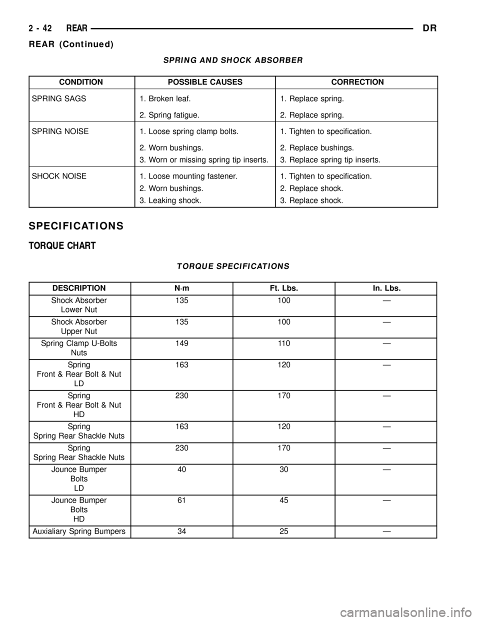
SPRING AND SHOCK ABSORBER
CONDITION POSSIBLE CAUSES CORRECTION
SPRING SAGS 1. Broken leaf. 1. Replace spring.
2. Spring fatigue. 2. Replace spring.
SPRING NOISE 1. Loose spring clamp bolts. 1. Tighten to specification.
2. Worn bushings. 2. Replace bushings.
3. Worn or missing spring tip inserts. 3. Replace spring tip inserts.
SHOCK NOISE 1. Loose mounting fastener. 1. Tighten to specification.
2. Worn bushings. 2. Replace shock.
3. Leaking shock. 3. Replace shock.
SPECIFICATIONS
TORQUE CHART
TORQUE SPECIFICATIONS
DESCRIPTION N´m Ft. Lbs. In. Lbs.
Shock Absorber
Lower Nut135 100 Ð
Shock Absorber
Upper Nut135 100 Ð
Spring Clamp U-Bolts
Nuts149 110 Ð
Spring
Front & Rear Bolt & Nut
LD163 120 Ð
Spring
Front & Rear Bolt & Nut
HD230 170 Ð
Spring
Spring Rear Shackle Nuts163 120 Ð
Spring
Spring Rear Shackle Nuts230 170 Ð
Jounce Bumper
Bolts
LD40 30 Ð
Jounce Bumper
Bolts
HD61 45 Ð
Auxialiary Spring Bumpers 34 25 Ð
2 - 42 REARDR
REAR (Continued)
Page 78 of 2627
BUSHINGS
REMOVAL
(1) Remove the spring from the vehicle.
(2) Make small relief cuts in the flared up end of
the bushing metal being careful not to cut the spring.
Use a punch to bend the flared bushing metal down
for push out.
(3) Position the spring eye in a press.
(4) Press the bushing out with an appropriate size
driver.
INSTALLATION
(1) Press new bushing into the spring eye with an
appropriate size driver. The bushing should be cen-
tered in the spring eye.
(2) Stake the outermetal of the bushing in a mini-
mum of six points to retain the bushing.
(3) Install the spring on the vehicle.
JOUNCE BUMPER
REMOVAL
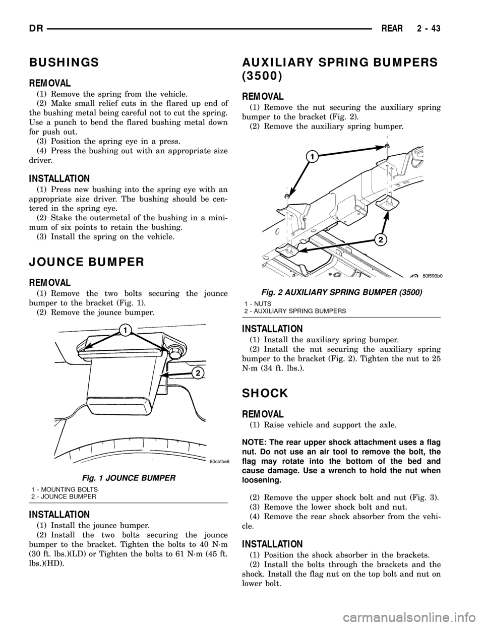
(1) Remove the two bolts securing the jounce
bumper to the bracket (Fig. 1).
(2) Remove the jounce bumper.
INSTALLATION
(1) Install the jounce bumper.
(2) Install the two bolts securing the jounce
bumper to the bracket. Tighten the bolts to 40 N´m
(30 ft. lbs.)(LD) or Tighten the bolts to 61 N´m (45 ft.
lbs.)(HD).
AUXILIARY SPRING BUMPERS
(3500)
REMOVAL
(1) Remove the nut securing the auxiliary spring
bumper to the bracket (Fig. 2).
(2) Remove the auxiliary spring bumper.
INSTALLATION
(1) Install the auxiliary spring bumper.
(2) Install the nut securing the auxiliary spring
bumper to the bracket (Fig. 2). Tighten the nut to 25
N´m (34 ft. lbs.).
SHOCK
REMOVAL
(1) Raise vehicle and support the axle.
NOTE: The rear upper shock attachment uses a flag
nut. Do not use an air tool to remove the bolt, the
flag may rotate into the bottom of the bed and
cause damage. Use a wrench to hold the nut when
loosening.
(2) Remove the upper shock bolt and nut (Fig. 3).
(3) Remove the lower shock bolt and nut.
(4) Remove the rear shock absorber from the vehi-
cle.
INSTALLATION
(1) Position the shock absorber in the brackets.
(2) Install the bolts through the brackets and the
shock. Install the flag nut on the top bolt and nut on
lower bolt.
Fig. 1 JOUNCE BUMPER
1 - MOUNTING BOLTS
2 - JOUNCE BUMPER
Fig. 2 AUXILIARY SPRING BUMPER (3500)
1 - NUTS
2 - AUXILIARY SPRING BUMPERS
DRREAR 2 - 43
Page 567 of 2627
INSTALLATION
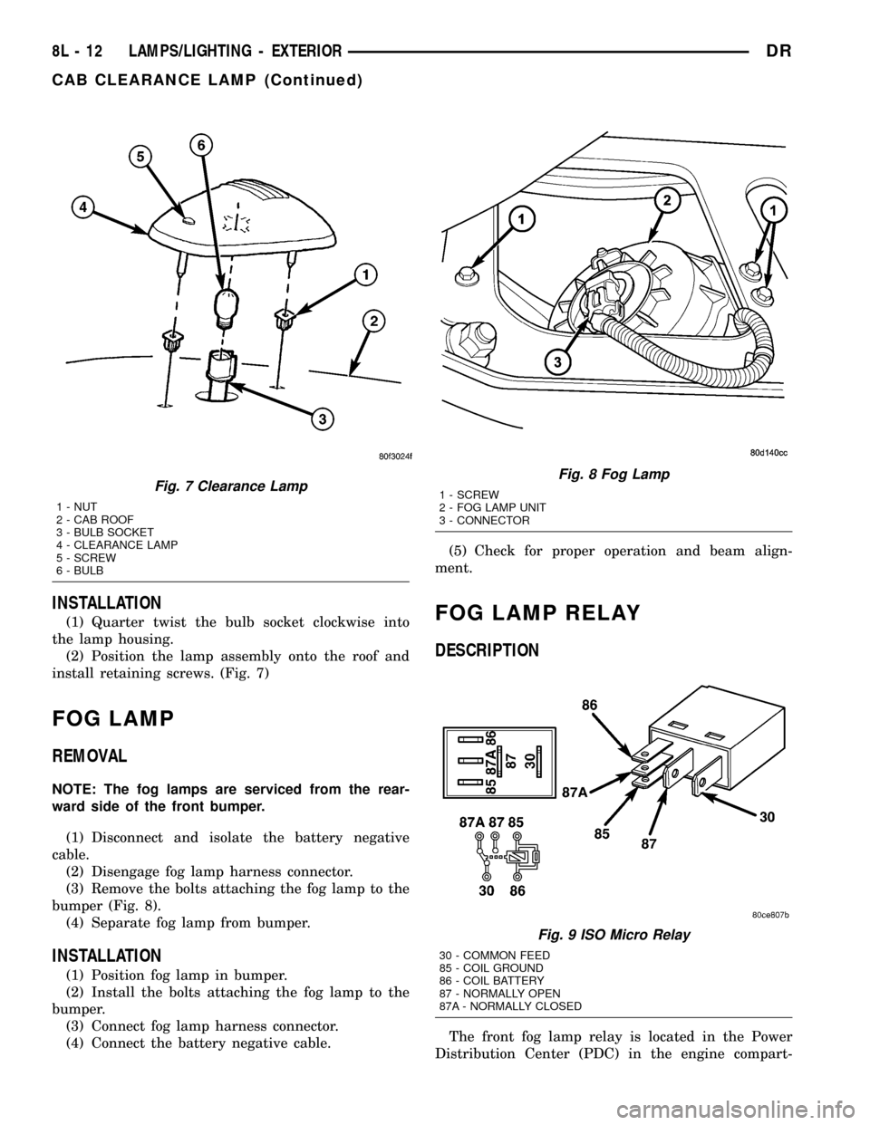
(1) Quarter twist the bulb socket clockwise into
the lamp housing.
(2) Position the lamp assembly onto the roof and
install retaining screws. (Fig. 7)
FOG LAMP
REMOVAL
NOTE: The fog lamps are serviced from the rear-
ward side of the front bumper.
(1) Disconnect and isolate the battery negative
cable.
(2) Disengage fog lamp harness connector.
(3) Remove the bolts attaching the fog lamp to the
bumper (Fig. 8).
(4) Separate fog lamp from bumper.
INSTALLATION
(1) Position fog lamp in bumper.
(2) Install the bolts attaching the fog lamp to the
bumper.
(3) Connect fog lamp harness connector.
(4) Connect the battery negative cable.(5) Check for proper operation and beam align-
ment.
FOG LAMP RELAY
DESCRIPTION
The front fog lamp relay is located in the Power
Distribution Center (PDC) in the engine compart-
Fig. 7 Clearance Lamp
1 - NUT
2 - CAB ROOF
3 - BULB SOCKET
4 - CLEARANCE LAMP
5 - SCREW
6 - BULB
Fig. 8 Fog Lamp
1 - SCREW
2 - FOG LAMP UNIT
3 - CONNECTOR
Fig. 9 ISO Micro Relay
30 - COMMON FEED
85 - COIL GROUND
86 - COIL BATTERY
87 - NORMALLY OPEN
87A - NORMALLY CLOSED
8L - 12 LAMPS/LIGHTING - EXTERIORDR
CAB CLEARANCE LAMP (Continued)