rear bumper DODGE RAM 1500 1998 2.G User Guide
[x] Cancel search | Manufacturer: DODGE, Model Year: 1998, Model line: RAM 1500, Model: DODGE RAM 1500 1998 2.GPages: 2627
Page 571 of 2627
(3) Install the bolts attaching headlamp unit to the
fender (Fig. 11).
(4) Align the seal and install the push pins.
(5) Connect the battery negative cable.
ADJUSTMENTS
Headlamps can be aligned using the screen method
provided in this section.
LAMP ALIGNMENT SCREEN PREPARATION
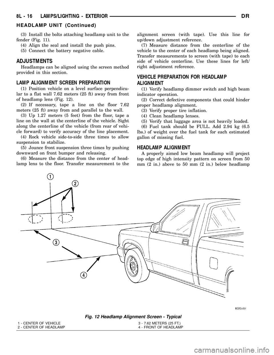
(1) Position vehicle on a level surface perpendicu-
lar to a flat wall 7.62 meters (25 ft) away from front
of headlamp lens (Fig. 12).
(2) If necessary, tape a line on the floor 7.62
meters (25 ft) away from and parallel to the wall.
(3) Up 1.27 meters (5 feet) from the floor, tape a
line on the wall at the centerline of the vehicle. Sight
along the centerline of the vehicle (from rear of vehi-
cle forward) to verify accuracy of the line placement.
(4) Rock vehicle side-to-side three times to allow
suspension to stabilize.
(5) Jounce front suspension three times by pushing
downward on front bumper and releasing.
(6) Measure the distance from the center of head-
lamp lens to the floor. Transfer measurement to thealignment screen (with tape). Use this line for
up/down adjustment reference.
(7) Measure distance from the centerline of the
vehicle to the center of each headlamp being aligned.
Transfer measurements to screen (with tape) to each
side of vehicle centerline. Use these lines for left/
right adjustment reference.
VEHICLE PREPARATION FOR HEADLAMP
ALIGNMENT
(1) Verify headlamp dimmer switch and high beam
indicator operation.
(2) Correct defective components that could hinder
proper headlamp alignment.
(3) Verify proper tire inflation.
(4) Clean headlamp lenses.
(5) Verify that luggage area is not heavily loaded.
(6) Fuel tank should be FULL. Add 2.94 kg (6.5
lbs.) of weight over the fuel tank for each estimated
gallon of missing fuel.
HEADLAMP ALIGNMENT
A properly aimed low beam headlamp will project
top edge of high intensity pattern on screen from 50
mm (2 in.) above to 50 mm (2 in.) below headlamp
Fig. 12 Headlamp Alignment Screen - Typical
1 - CENTER OF VEHICLE
2 - CENTER OF HEADLAMP3 - 7.62 METERS (25 FT.)
4 - FRONT OF HEADLAMP
8L - 16 LAMPS/LIGHTING - EXTERIORDR
HEADLAMP UNIT (Continued)
Page 572 of 2627
centerline. The side-to-side outboard edge of high
intensity pattern should be from 150 mm (6 in.) left
to 150 mm (6 in.) right of headlamp centerline (Fig.
12).The preferred headlamp alignment is 1(
down for the up/down adjustment and 0 for the
left/right adjustment.The high beam pattern
should be correct when the low beams are aligned
properly.
To adjust low beam headlamp, rotate vertical align-
ment screw to achieve the specified aim.
LICENSE PLATE LAMP
REMOVAL
(1) Disconnect and isolate the battery negative
cable.
(2) Grasp license plate bulb socket and 1/4 turn
left to release from the license plate lamp unit.
(3) Pull bulb from license plate lamp socket.
INSTALLATION
(1) Install the bulb in the socket.
(2) Install the socket in to the license plate lamp
unit and 1/4 turn to lock.
(3) Connect the battery negative cable.
LICENSE PLATE LAMP UNIT
REMOVAL
(1) Disconnect and isolate the battery negative
cable.
(2) Disconnect the harness connector.
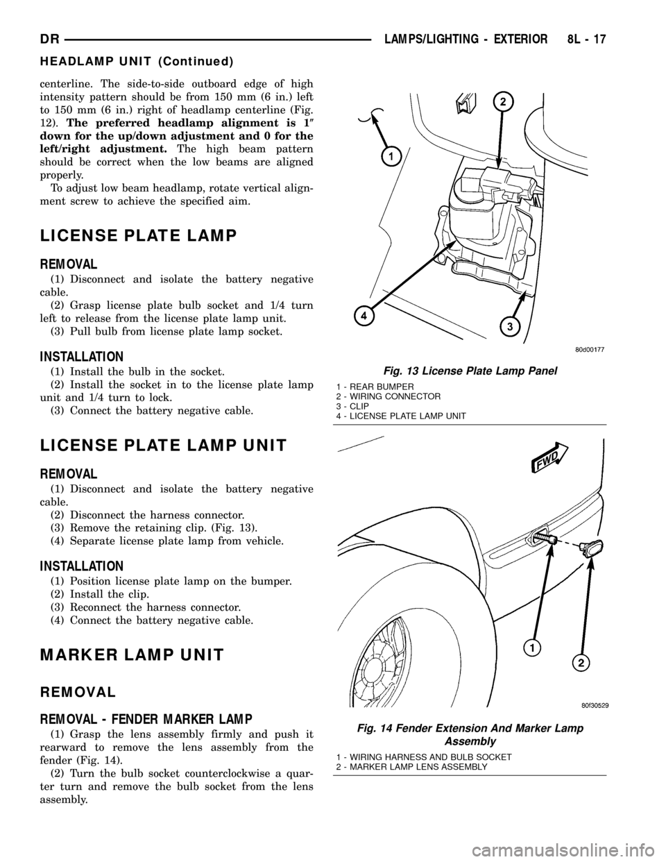
(3) Remove the retaining clip. (Fig. 13).
(4) Separate license plate lamp from vehicle.
INSTALLATION
(1) Position license plate lamp on the bumper.
(2) Install the clip.
(3) Reconnect the harness connector.
(4) Connect the battery negative cable.
MARKER LAMP UNIT
REMOVAL
REMOVAL - FENDER MARKER LAMP
(1) Grasp the lens assembly firmly and push it
rearward to remove the lens assembly from the
fender (Fig. 14).
(2) Turn the bulb socket counterclockwise a quar-
ter turn and remove the bulb socket from the lens
assembly.
Fig. 13 License Plate Lamp Panel
1 - REAR BUMPER
2 - WIRING CONNECTOR
3 - CLIP
4 - LICENSE PLATE LAMP UNIT
Fig. 14 Fender Extension And Marker Lamp
Assembly
1 - WIRING HARNESS AND BULB SOCKET
2 - MARKER LAMP LENS ASSEMBLY
DRLAMPS/LIGHTING - EXTERIOR 8L - 17
HEADLAMP UNIT (Continued)
Page 579 of 2627
TRAILER TOW WIRING
DESCRIPTION
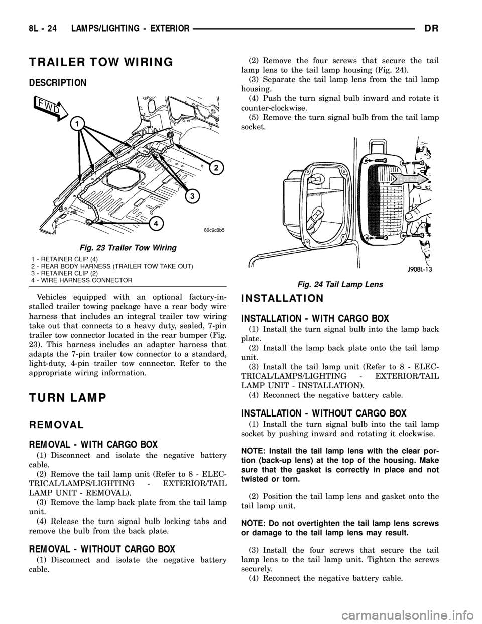
Vehicles equipped with an optional factory-in-
stalled trailer towing package have a rear body wire
harness that includes an integral trailer tow wiring
take out that connects to a heavy duty, sealed, 7-pin
trailer tow connector located in the rear bumper (Fig.
23). This harness includes an adapter harness that
adapts the 7-pin trailer tow connector to a standard,
light-duty, 4-pin trailer tow connector. Refer to the
appropriate wiring information.
TURN LAMP
REMOVAL
REMOVAL - WITH CARGO BOX
(1) Disconnect and isolate the negative battery
cable.
(2) Remove the tail lamp unit (Refer to 8 - ELEC-
TRICAL/LAMPS/LIGHTING - EXTERIOR/TAIL
LAMP UNIT - REMOVAL).
(3) Remove the lamp back plate from the tail lamp
unit.
(4) Release the turn signal bulb locking tabs and
remove the bulb from the back plate.
REMOVAL - WITHOUT CARGO BOX
(1) Disconnect and isolate the negative battery
cable.(2) Remove the four screws that secure the tail
lamp lens to the tail lamp housing (Fig. 24).
(3) Separate the tail lamp lens from the tail lamp
housing.
(4) Push the turn signal bulb inward and rotate it
counter-clockwise.
(5) Remove the turn signal bulb from the tail lamp
socket.
INSTALLATION
INSTALLATION - WITH CARGO BOX
(1) Install the turn signal bulb into the lamp back
plate.
(2) Install the lamp back plate onto the tail lamp
unit.
(3) Install the tail lamp unit (Refer to 8 - ELEC-
TRICAL/LAMPS/LIGHTING - EXTERIOR/TAIL
LAMP UNIT - INSTALLATION).
(4) Reconnect the negative battery cable.
INSTALLATION - WITHOUT CARGO BOX
(1) Install the turn signal bulb into the tail lamp
socket by pushing inward and rotating it clockwise.
NOTE: Install the tail lamp lens with the clear por-
tion (back-up lens) at the top of the housing. Make
sure that the gasket is correctly in place and not
twisted or torn.
(2) Position the tail lamp lens and gasket onto the
tail lamp unit.
NOTE: Do not overtighten the tail lamp lens screws
or damage to the tail lamp lens may result.
(3) Install the four screws that secure the tail
lamp lens to the tail lamp unit. Tighten the screws
securely.
(4) Reconnect the negative battery cable.
Fig. 23 Trailer Tow Wiring
1 - RETAINER CLIP (4)
2 - REAR BODY HARNESS (TRAILER TOW TAKE OUT)
3 - RETAINER CLIP (2)
4 - WIRE HARNESS CONNECTOR
Fig. 24 Tail Lamp Lens
8L - 24 LAMPS/LIGHTING - EXTERIORDR
Page 1158 of 2627
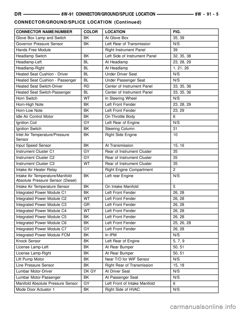
CONNECTOR NAME/NUMBER COLOR LOCATION FIG.
Glove Box Lamp and Switch BK At Glove Box 35, 39
Governor Pressure Sensor BK Left Rear of Transmission N/S
Hands Free Module Right Instrument Panel 39
Headlamp Switch BK Left Side of Instrument Panel 32, 35, 38
Headlamp-Left BL At Headlamp 23, 28, 29
Headlamp-Right BL At Headlamp 1, 21, 26
Heated Seat Cushion - Driver BL Under Driver Seat N/S
Heated Seat Cushion - Passenger BL Under Passenger Seat N/S
Heated Seat Switch-Driver RD Center of Instrument Panel 33, 35, 36
Heated Seat Switch-Passenger BL Center of Instrument Panel 33, 35, 36
Horn Switch WT In Steering Wheel N/S
Horn-High Note BK Left Front Fender 23, 28, 29
Horn-Low Note BK Left Front Fender 23, 29
Idle Air Control Motor BK On Throttle Body 6
Ignition Coil GY Left Rear of Engine N/S
Ignition Switch BK Steering Column 31
Inlet Air Temperature/Pressure
SensorBK Right Side Engine 10
Input Speed Sensor BK At Transmission 15, 16
Instrument Cluster C1 GY Rear of Instrument Cluster 35
Instrument Cluster C2 GY Rear of Instrument Cluster 35
Instrument Cluster C3 WT Rear of Instrument Cluster 35
Intake Air Heater Relay Right Engine Compartment 2
Intake Air Temperature/Manifold
Absolute Pressure Sensor (Diesel)BK Left rear Engine N/S
Intake Air Temperature Sensor BK On Intake Manifold 5
Integrated Power Module C1 BK Left Front Fender 26, 28
Integrated Power Module C2 WT Left Front Fender 26, 28
Integrated Power Module C3 GR Left Front Fender 26, 28
Integrated Power Module C4 WT Left Front Fender 26, 28
Integrated Power Module C5 BK Left Front Fender 26, 28
Integrated Power Module C6 BK Left Front Fender 25, 26, 28
Integrated Power Module C7 GY Left Front Fender 26, 28
Integrated Power Module FCM BK In IPM N/S
Knock Sensor BK Left Rear of Engine 5, 7, 9
License Lamp-Left BK At Rear Bumper 50, 51
License Lamp-Right BK At Rear Bumper 50, 51
Lift Pump Motor BK Near T/O for WIF Sensor N/S
Line Pressure Sensor BK Right Rear of Transmission 15, 18
Lumbar Motor-Driver DK GY At Driver Seat N/S
Lumbar Motor-Passenger BK At Passenger Seat N/S
Manifold Absolute Pressure Sensor GY Left Front of Intake Manifold 6
Mode Door Actuator 1 BK Right Side of HVAC N/S
DR8W-91 CONNECTOR/GROUND/SPLICE LOCATION 8W - 91 - 5
CONNECTOR/GROUND/SPLICE LOCATION (Continued)
Page 1215 of 2627
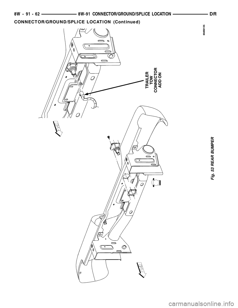
Fig. 53 REAR BUMPER
8W - 91 - 62 8W-91 CONNECTOR/GROUND/SPLICE LOCATIONDR
CONNECTOR/GROUND/SPLICE LOCATION (Continued)
Page 1440 of 2627
CAUTION: The structural cover must be held tightly
against the corner formed by the engine and the
transmission clutch housing during tightening
sequence. Failure to do so may cause damage to
the cover and engine noise.
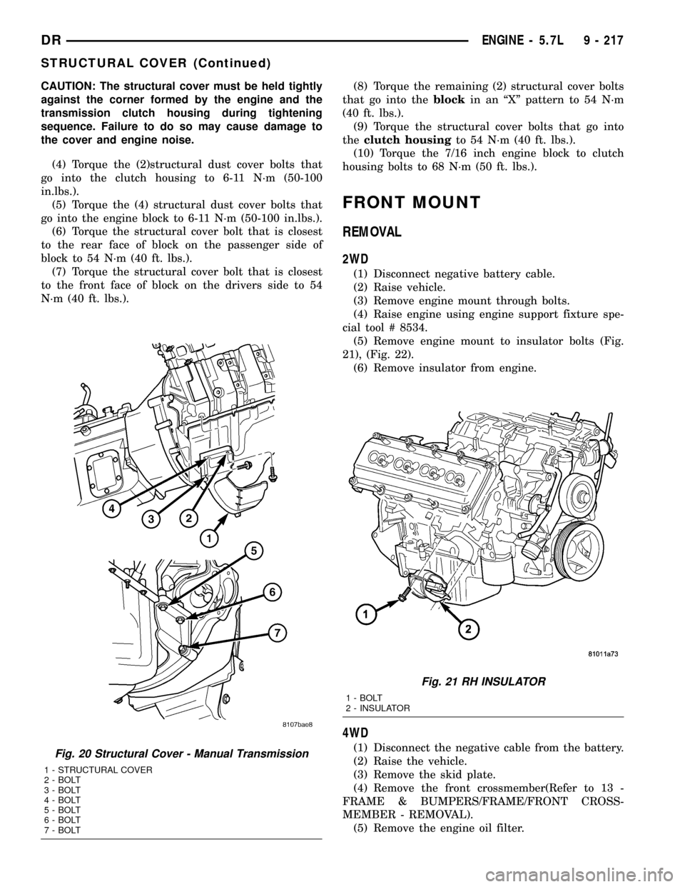
(4) Torque the (2)structural dust cover bolts that
go into the clutch housing to 6-11 N´m (50-100
in.lbs.).
(5) Torque the (4) structural dust cover bolts that
go into the engine block to 6-11 N´m (50-100 in.lbs.).
(6) Torque the structural cover bolt that is closest
to the rear face of block on the passenger side of
block to 54 N´m (40 ft. lbs.).
(7) Torque the structural cover bolt that is closest
to the front face of block on the drivers side to 54
N´m (40 ft. lbs.).(8) Torque the remaining (2) structural cover bolts
that go into theblockin an ªXº pattern to 54 N´m
(40 ft. lbs.).
(9) Torque the structural cover bolts that go into
theclutch housingto 54 N´m (40 ft. lbs.).
(10) Torque the 7/16 inch engine block to clutch
housing bolts to 68 N´m (50 ft. lbs.).
FRONT MOUNT
REMOVAL
2WD
(1) Disconnect negative battery cable.
(2) Raise vehicle.
(3) Remove engine mount through bolts.
(4) Raise engine using engine support fixture spe-
cial tool # 8534.
(5) Remove engine mount to insulator bolts (Fig.
21), (Fig. 22).
(6) Remove insulator from engine.
4WD
(1) Disconnect the negative cable from the battery.
(2) Raise the vehicle.
(3) Remove the skid plate.
(4) Remove the front crossmember(Refer to 13 -
FRAME & BUMPERS/FRAME/FRONT CROSS-
MEMBER - REMOVAL).
(5) Remove the engine oil filter.Fig. 20 Structural Cover - Manual Transmission
1 - STRUCTURAL COVER
2 - BOLT
3 - BOLT
4 - BOLT
5 - BOLT
6 - BOLT
7 - BOLT
Fig. 21 RH INSULATOR
1 - BOLT
2 - INSULATOR
DRENGINE - 5.7L 9 - 217
STRUCTURAL COVER (Continued)
Page 1443 of 2627
(8) Torque the (3) bolts that attach the front axle
to the left engine bracket to 101 N´m (75 ft. lbs.).
(9) Install the engine oil filter, if removed.
(10) Install the front crossmember(Refer to 13 -
FRAME & BUMPERS/FRAME/FRONT CROSS-
MEMBER - INSTALLATION).
(11) Install the skid plate.
(12) Lower the vehicle.
(13) Reconnect the negative battery cable.
REAR MOUNT
REMOVAL
(1) Raise the vehicle on a hoist.
(2) Using a suitable jack, support transmission.
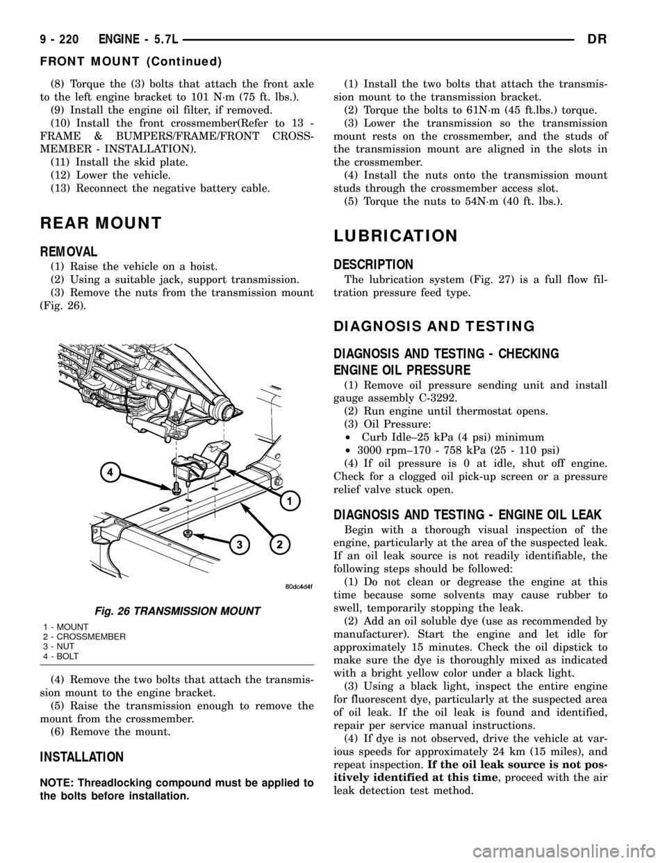
(3) Remove the nuts from the transmission mount
(Fig. 26).
(4) Remove the two bolts that attach the transmis-
sion mount to the engine bracket.
(5) Raise the transmission enough to remove the
mount from the crossmember.
(6) Remove the mount.
INSTALLATION
NOTE: Threadlocking compound must be applied to
the bolts before installation.(1) Install the two bolts that attach the transmis-
sion mount to the transmission bracket.
(2) Torque the bolts to 61N´m (45 ft.lbs.) torque.
(3) Lower the transmission so the transmission
mount rests on the crossmember, and the studs of
the transmission mount are aligned in the slots in
the crossmember.
(4) Install the nuts onto the transmission mount
studs through the crossmember access slot.
(5) Torque the nuts to 54N´m (40 ft. lbs.).
LUBRICATION
DESCRIPTION
The lubrication system (Fig. 27) is a full flow fil-
tration pressure feed type.
DIAGNOSIS AND TESTING
DIAGNOSIS AND TESTING - CHECKING
ENGINE OIL PRESSURE
(1) Remove oil pressure sending unit and install
gauge assembly C-3292.
(2) Run engine until thermostat opens.
(3) Oil Pressure:
²Curb Idle±25 kPa (4 psi) minimum
²3000 rpm±170 - 758 kPa (25 - 110 psi)
(4) If oil pressure is 0 at idle, shut off engine.
Check for a clogged oil pick-up screen or a pressure
relief valve stuck open.
DIAGNOSIS AND TESTING - ENGINE OIL LEAK
Begin with a thorough visual inspection of the
engine, particularly at the area of the suspected leak.
If an oil leak source is not readily identifiable, the
following steps should be followed:
(1) Do not clean or degrease the engine at this
time because some solvents may cause rubber to
swell, temporarily stopping the leak.
(2) Add an oil soluble dye (use as recommended by
manufacturer). Start the engine and let idle for
approximately 15 minutes. Check the oil dipstick to
make sure the dye is thoroughly mixed as indicated
with a bright yellow color under a black light.
(3) Using a black light, inspect the entire engine
for fluorescent dye, particularly at the suspected area
of oil leak. If the oil leak is found and identified,
repair per service manual instructions.
(4) If dye is not observed, drive the vehicle at var-
ious speeds for approximately 24 km (15 miles), and
repeat inspection.If the oil leak source is not pos-
itively identified at this time, proceed with the air
leak detection test method.
Fig. 26 TRANSMISSION MOUNT
1 - MOUNT
2 - CROSSMEMBER
3 - NUT
4 - BOLT
9 - 220 ENGINE - 5.7LDR
FRONT MOUNT (Continued)
Page 1544 of 2627
FRAMES & BUMPERS
TABLE OF CONTENTS
page page
BUMPERS
SPECIFICATIONS - TORQUE...............1
FRONT AIR DAM
REMOVAL.............................2
INSTALLATION..........................2
FRONT BUMPER
REMOVAL.............................2
INSTALLATION..........................2
FRONT FASCIA
REMOVAL.............................2
INSTALLATION..........................3
REAR BUMPER
REMOVAL.............................3
INSTALLATION..........................4
FRAME
WARNING
SAFETY PRECAUTIONS AND WARNINGS . . . 4
STANDARD PROCEDURE
STANDARD PROCEDURE - LIGHT DUTY
FRONT FRAME RAIL TIP REPLACEMENT....4
STANDARD PROCEDURE - HYDROFORM
FENDER RAIL REPAIR.................11
STANDARD PROCEDURE - REAR FRAME
H-SECTION REPLACEMENT.............13SPECIFICATIONS
SPECIFICATIONS - WELD PROCESS......15
SPECIFICATIONS - FRAME DIMENSIONS . . . 16
SPECIFICATIONS - TORQUE............22
FRONT CROSSMEMBER
REMOVAL.............................22
INSTALLATION.........................22
FRONT SKID PLATE
REMOVAL.............................23
INSTALLATION.........................23
FRONT TOW HOOK ASSEMBLY
REMOVAL.............................23
INSTALLATION.........................23
TRANSMISSION CROSSMEMBER
REMOVAL.............................24
INSTALLATION.........................24
TRAILER HITCH
REMOVAL.............................25
INSTALLATION.........................25
TRANSFER CASE SKID PLATE
REMOVAL.............................26
INSTALLATION.........................26
BUMPERS
SPECIFICATIONS - TORQUE
TORQUE SPECIFICATIONS
DESCRIPTION N´m Ft. Lbs. In. Lbs.
Front bumper center bracket nuts 95 70 Ð
Front bumper stud plate nuts 95 70 Ð
License plate hitch reinforcement bolts 54 40 Ð
Rear bumper support bracket stud plate nuts 54 40 Ð
Rear bumper support bracket to hitch bolts 54 40 Ð
Rear bumper to hitch bolts 54 40 Ð
DRFRAMES & BUMPERS 13 - 1
Page 1546 of 2627
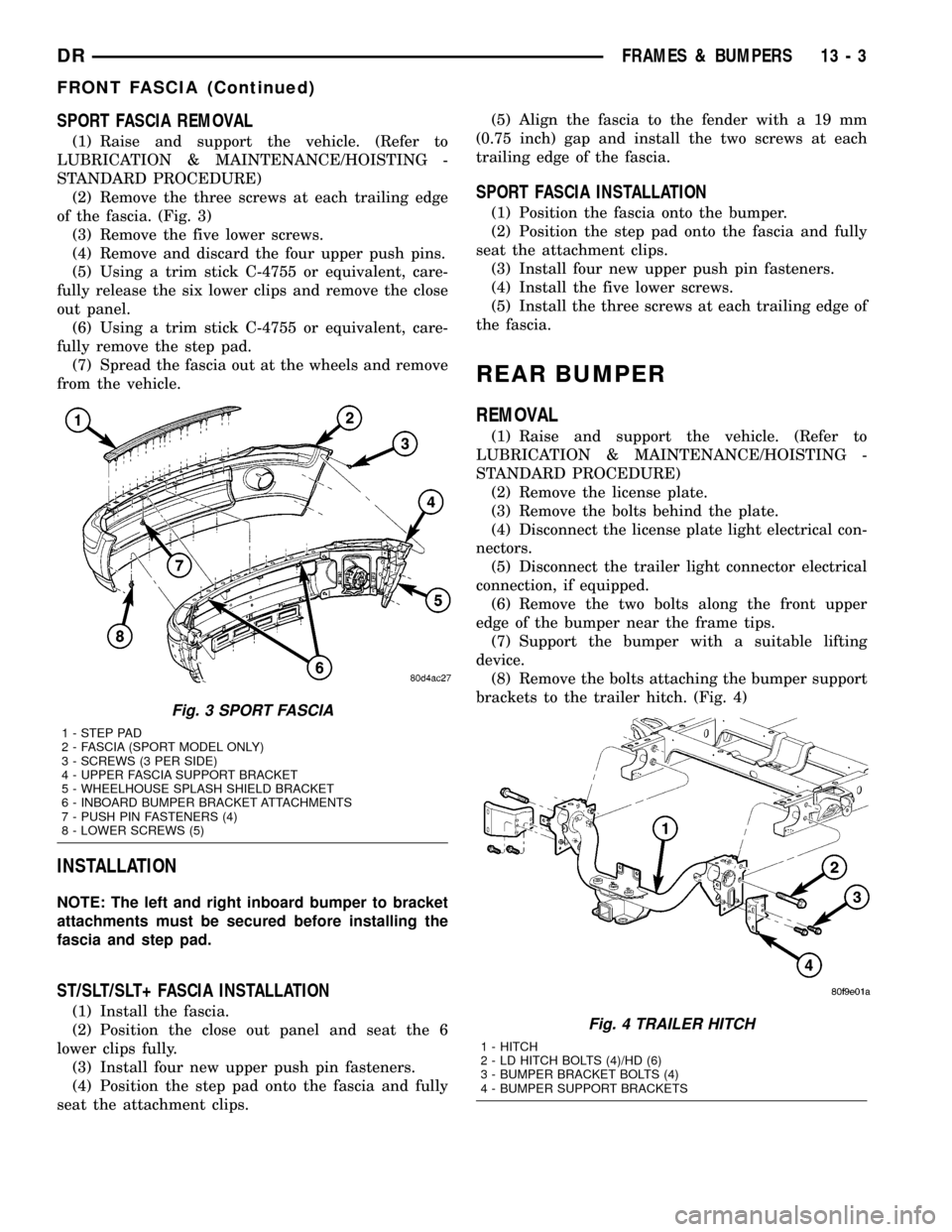
SPORT FASCIA REMOVAL
(1) Raise and support the vehicle. (Refer to
LUBRICATION & MAINTENANCE/HOISTING -
STANDARD PROCEDURE)
(2) Remove the three screws at each trailing edge
of the fascia. (Fig. 3)
(3) Remove the five lower screws.
(4) Remove and discard the four upper push pins.
(5) Using a trim stick C-4755 or equivalent, care-
fully release the six lower clips and remove the close
out panel.
(6) Using a trim stick C-4755 or equivalent, care-
fully remove the step pad.
(7) Spread the fascia out at the wheels and remove
from the vehicle.
INSTALLATION
NOTE: The left and right inboard bumper to bracket
attachments must be secured before installing the
fascia and step pad.
ST/SLT/SLT+ FASCIA INSTALLATION
(1) Install the fascia.
(2) Position the close out panel and seat the 6
lower clips fully.
(3) Install four new upper push pin fasteners.
(4) Position the step pad onto the fascia and fully
seat the attachment clips.(5) Align the fascia to the fender with a 19 mm
(0.75 inch) gap and install the two screws at each
trailing edge of the fascia.
SPORT FASCIA INSTALLATION
(1) Position the fascia onto the bumper.
(2) Position the step pad onto the fascia and fully
seat the attachment clips.
(3) Install four new upper push pin fasteners.
(4) Install the five lower screws.
(5) Install the three screws at each trailing edge of
the fascia.
REAR BUMPER
REMOVAL
(1) Raise and support the vehicle. (Refer to
LUBRICATION & MAINTENANCE/HOISTING -
STANDARD PROCEDURE)
(2) Remove the license plate.
(3) Remove the bolts behind the plate.
(4) Disconnect the license plate light electrical con-
nectors.
(5) Disconnect the trailer light connector electrical
connection, if equipped.
(6) Remove the two bolts along the front upper
edge of the bumper near the frame tips.
(7) Support the bumper with a suitable lifting
device.
(8) Remove the bolts attaching the bumper support
brackets to the trailer hitch. (Fig. 4)
Fig. 3 SPORT FASCIA
1 - STEP PAD
2 - FASCIA (SPORT MODEL ONLY)
3 - SCREWS (3 PER SIDE)
4 - UPPER FASCIA SUPPORT BRACKET
5 - WHEELHOUSE SPLASH SHIELD BRACKET
6 - INBOARD BUMPER BRACKET ATTACHMENTS
7 - PUSH PIN FASTENERS (4)
8 - LOWER SCREWS (5)
Fig. 4 TRAILER HITCH
1 - HITCH
2 - LD HITCH BOLTS (4)/HD (6)
3 - BUMPER BRACKET BOLTS (4)
4 - BUMPER SUPPORT BRACKETS
DRFRAMES & BUMPERS 13 - 3
FRONT FASCIA (Continued)
Page 1547 of 2627
INSTALLATION
(1) Align the holes in the bumpers to the trailer
hitch pins and install the bumper.
(2) Install the support bracket to the hitch bolts,
loosely.
(3) Install the front upper edge to the trailer hitch
bolts and tighten to 54 N´m (40 ft. lbs.).
(4) Install the license plate reinforcement to hitch
bolts and tighten to 54 N´m (40 ft. lbs.).
(5) Tighten the left bumper bracket bolts to 54
N´m (40 ft. lbs.).
(6) Tighten the right bumper bracket bolts to 54
N´m (40 ft. lbs.).
(7) Connect the trailer light connector electrical
connection, if equipped.
(8) Connect the license plate light electrical con-
nectors.
(9) Install the license plate.
FRAME
WARNING
SAFETY PRECAUTIONS AND WARNINGS
WARNING: USE EYE PROTECTION WHEN GRIND-
ING OR WELDING METAL, SERIOUS EYE INJURY
CAN RESULT.
²BEFORE PROCEEDING WITH FRAME REPAIR
INVOLVING GRINDING OR WELDING, VERIFY THAT
VEHICLE FUEL SYSTEM IS NOT LEAKING OR IN
CONTACT WITH REPAIR AREA, PERSONAL INJURY
CAN RESULT.
²DO NOT ALLOW OPEN FLAME OR HEAT AND
METAL SPATTER FROM ARC WELDING, TO CON-
TACT PLASTIC BODY PANELS. FIRE OR EXPLO-
SION CAN RESULT.
²WHEN WELDED FRAME COMPONENTS ARE
REPLACED, ENSURE COMPLETE PENETRATION
WELD IS ACHIEVED DURING INSTALLATION. IF
NOT, DANGEROUS OPERATING CONDITIONS CAN
RESULT.
²STAND CLEAR OF CABLES OR CHAINS ON
PULLING EQUIPMENT DURING FRAME STRAIGHT-
ENING OPERATIONS, PERSONAL INJURY CAN
RESULT.
²DO NOT VENTURE UNDER A HOISTED VEHI-
CLE THAT IS NOT SUPPORTED ON SAFETY
STANDS, PERSONAL INJURY CAN RESULT.
CAUTION: 1500 series Dodge Ram Trucks (2002 and
later) are not designed for snow plow equipment.The front collision repair tips must not be installed
on any truck equipped with a snow plow, or even
intended to be equipped with a snow plow.
CAUTION: Do not reuse damaged fasteners, quality
of repair would be suspect. Failure to use only pro-
duction fasteners or fasteners of equivalent hard-
ness can result in loosening or failure. Do not drill
any holes in the frame that are not specifically out-
lined in this or other, DaimlerChrysler procedure as
frame rail failure can result. When using heat to
straighten frame components do not exceed 566ÉC
(1050ÉF), metal fatigue can result.
STANDARD PROCEDURE
STANDARD PROCEDURE - LIGHT DUTY FRONT
FRAME RAIL TIP REPLACEMENT
CAUTION: This procedure is designed to replace
the front frame rail tips that have been damaged in
the crush initiator zones. Prior to any cutting, the
vehicle must be mounted on the appropriate frame
repair equipment (ªframe rackº), checked with three
dimensional measuring equipment, and the neces-
sary pull corrections made. If damage remains in
the frame beyond the area covered by this service
part after the pull, the frame must be replaced in its
entirety.
NOTE: Procedures for 4X2 and 4X4 are common
except as noted in this procedure.
(1) Before proceding with this repair procedure
review the required service warnings and precau-
tions. (Refer to 13 - FRAME & BUMPERS/FRAME -
WARNING)
(2) Disconnect and isolate the battery negative
cable.
(3) Remove the front wheelhouse splash shield.
(Refer to 23 - BODY/EXTERIOR/FRONT WHEEL-
HOUSE SPLASH SHIELD - REMOVAL)
(4) Remove the bolts and position aside the wire
harness and grounds, if required.
(5) Remove the front bumper. (Refer to 13 -
FRAME & BUMPERS/BUMPERS/FRONT BUMPER
- REMOVAL)
(6) Loosen and lower the stabilizer bar mount and
bar. (Refer to 2 - SUSPENSION/FRONT/STABI-
LIZER BAR - REMOVAL)
13 - 4 FRAMES & BUMPERSDR
REAR BUMPER (Continued)