Ignition coil DODGE RAM 1500 1998 2.G Owner's Guide
[x] Cancel search | Manufacturer: DODGE, Model Year: 1998, Model line: RAM 1500, Model: DODGE RAM 1500 1998 2.GPages: 2627
Page 832 of 2627

8W-30 FUEL/IGNITION SYSTEM
Component Page
A/C Compressor Clutch Relay............ 8W-30-9, 58
A/C Pressure Transducer......... 8W-30-23, 28, 29, 45
Accelerator Pedal Position Sensor . . . 8W-30-29, 47, 64, 65
Adjustable Pedal Motor................. 8W-30-61
Adjustable Pedal Relay.................. 8W-30-61
Adjustable Pedal Switch................. 8W-30-61
Ambient Temperature Sensor............. 8W-30-30
Auto Shut Down Relay................... 8W-30-4
Battery............................ 8W-30-52
Battery Temperature Sensor............ 8W-30-12, 56
Brake Lamp Switch............. 8W-30-8, 36, 57, 63
Camshaft Position Sensor........ 8W-30-10, 29, 45, 46
Capacitor........................... 8W-30-13
Clockspring..................... 8W-30-8, 36, 59
Coil On Plug No. 1.................. 8W-30-14, 39
Coil On Plug No. 2.................. 8W-30-15, 37
Coil On Plug No. 3.................. 8W-30-14, 39
Coil On Plug No. 4.................. 8W-30-15, 37
Coil On Plug No. 5.................. 8W-30-16, 39
Coil On Plug No. 6.................. 8W-30-13, 37
Coil On Plug No. 7.................. 8W-30-16, 39
Coil On Plug No. 8.................. 8W-30-13, 37
Condenser Fan Relay.................... 8W-30-9
Controller Antilock Brake............ 8W-30-6, 11, 57
Crankshaft Position Sensor............ 8W-30-10, 46
Data Link Connector............... 8W-30-9, 22, 55
Data Link Connector-Engine.............. 8W-30-51
EGR Solenoid................... 8W-30-28, 29, 32
Electronic Throttle Control Module.......... 8W-30-35
Engine Control Module....... 8W-30-42, 43, 44, 45, 46,
47, 48, 49, 50, 51, 52, 53, 54,
55, 56, 57, 58, 59, 60, 62, 63, 64, 65
Engine Coolant Temperature Sensor.... 8W-30-23, 41, 47
Engine Oil Pressure Switch.......... 8W-30-2, 53, 56
EVAP/Purge Solenoid................... 8W-30-12
Front Control Module................... 8W-30-61
Fuel Control Actuator................... 8W-30-50
Fuel Heater......................... 8W-30-60
Fuel Heater Relay..................... 8W-30-60
Fuel Injector No. 1.................. 8W-30-14, 40
Fuel Injector No. 2.................. 8W-30-15, 38
Fuel Injector No. 3.................. 8W-30-14, 40
Fuel Injector No. 4.................. 8W-30-15, 38
Fuel Injector No. 5.................. 8W-30-14, 40
Fuel Injector No. 6.................. 8W-30-15, 38
Fuel Injector No. 7.................. 8W-30-16, 40
Fuel Injector No. 8.................. 8W-30-13, 38
Fuel Injector Pack No. 1................. 8W-30-42
Fuel Injector Pack No. 2............ 8W-30-42, 43, 44
Fuel Injector Pack No. 3................. 8W-30-44
Fuel Pump Module................... 8W-30-3, 58
Fuel Pump Motor...................... 8W-30-48
Fuel Pump Relay....................... 8W-30-3
Fuse 2.............................. 8W-30-4
Fuse 5........................... 8W-30-25, 62
Fuse 12............................ 8W-30-60
Fuse 17............................. 8W-30-3
Fuse 19............................ 8W-30-52
Fuse 23............................. 8W-30-2Component Page
Fuse 36.......................... 8W-30-54, 61
Fuse 40............................ 8W-30-61
Fuse 49............................. 8W-30-4
Fuse 50..................... 8W-30-2, 55, 58, 62
Fusible Link......................... 8W-30-52
G104........................ 8W-30-3, 8, 25, 60
G105............................ 8W-30-56, 58
G107........... 8W-30-2, 7, 15, 18, 19, 20, 21, 30, 32
G114 .............................. 8W-30-53
G120............................ 8W-30-51, 60
G201............................... 8W-30-6
G202.............................. 8W-30-61
Generator......................... 8W-30-7, 51
Idle Air Control Motor................... 8W-30-9
Ignition Switch..................... 8W-30-6, 22
Inlet Air Temperature Sensor............. 8W-30-49
Input Speed Sensor.................... 8W-30-24
Instrument Cluster.................... 8W-30-30
Intake Air Heater Relay No. 1............. 8W-30-56
Intake Air Heater Relay No. 2............. 8W-30-56
Intake Air Temperature Sensor.......... 8W-30-23, 41
Intake Air Temperature/Manifold Absolute
Pressure Sensor..................... 8W-30-50
Integrated Power Module.... 8W-30-2, 3, 4, 9, 25, 52, 54,
55, 58, 60, 61, 62, 64
Knock Sensor........................ 8W-30-31
Knock Sensor-Left..................... 8W-30-33
Knock Sensor-Right.................... 8W-30-33
Lift Pump Motor...................... 8W-30-51
Line Pressure Sensor................... 8W-30-17
Manifold Absolute Pressure Sensor..... 8W-30-23, 29, 41
Natural Vacuum Leak Detection Assembly..... 8W-30-7
Output Speed Sensor................. 8W-30-24, 62
Oxygen Sensor 1/1 Upstream........... 8W-30-20, 21
Oxygen Sensor 1/2 Downstream......... 8W-30-18, 19
Oxygen Sensor 2/1 Upstream........... 8W-30-20, 21
Oxygen Sensor 2/2 Downstream......... 8W-30-18, 19
Oxygen Sensor Downstream Relay........... 8W-30-4
Power Steering Pressure Switch............ 8W-30-7
Powertrain Control Module....... 8W-30-2, 3, 4, 5, 6, 7,
8, 9, 10, 11, 12, 13, 14, 15, 16,
17, 18, 19, 20, 21, 22, 23, 24,
25, 26, 27, 28, 29, 30, 31, 32,
33, 35, 36, 37, 38, 39, 40, 41
PTCNo.1 ....................... 8W-30-3, 9, 58
Pto Switch........................... 8W-30-6
Speed Control Servo.................. 8W-30-8, 63
Speed Control Switch-Left............. 8W-30-36, 59
Speed Control Switch-Right............ 8W-30-36, 59
Starter Motor Relay.................. 8W-30-2, 64
Throttle Position Sensor................. 8W-30-17
Tow/Haul Overdrive Switch............. 8W-30-6, 64
Transmission Control Relay............ 8W-30-25, 62
Transmission Range Sensor............... 8W-30-64
Transmission Solenoid Assembly......... 8W-30-54, 62
Transmission Solenoid/TRS Assembly . 8W-30-5, 25, 26, 27
Vacuum Pump........................ 8W-30-58
Vistronic Fan Drive.................... 8W-30-54
Water In Fuel Sensor................ 8W-30-47, 48
DR8W-30 FUEL/IGNITION SYSTEM 8W - 30 - 1
Page 1100 of 2627
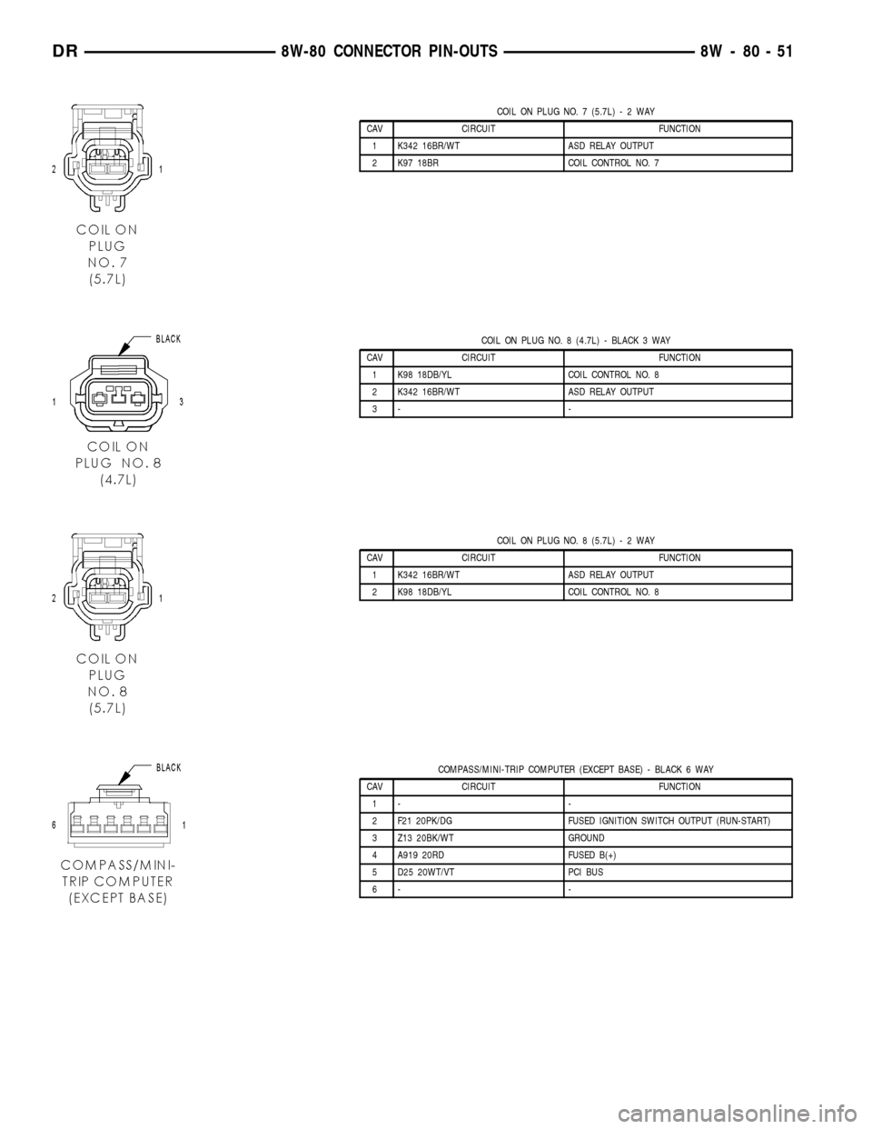
COIL ON PLUG NO. 7 (5.7L)-2WAY
CAV CIRCUIT FUNCTION
1 K342 16BR/WT ASD RELAY OUTPUT
2 K97 18BR COIL CONTROL NO. 7
COIL ON PLUG NO. 8 (4.7L) - BLACK 3 WAY
CAV CIRCUIT FUNCTION
1 K98 18DB/YL COIL CONTROL NO. 8
2 K342 16BR/WT ASD RELAY OUTPUT
3- -
COIL ON PLUG NO. 8 (5.7L)-2WAY
CAV CIRCUIT FUNCTION
1 K342 16BR/WT ASD RELAY OUTPUT
2 K98 18DB/YL COIL CONTROL NO. 8
COMPASS/MINI-TRIP COMPUTER (EXCEPT BASE) - BLACK 6 WAY
CAV CIRCUIT FUNCTION
1- -
2 F21 20PK/DG FUSED IGNITION SWITCH OUTPUT (RUN-START)
3 Z13 20BK/WT GROUND
4 A919 20RD FUSED B(+)
5 D25 20WT/VT PCI BUS
6- -
DR8W-80 CONNECTOR PIN-OUTS 8W - 80 - 51
Page 1137 of 2627
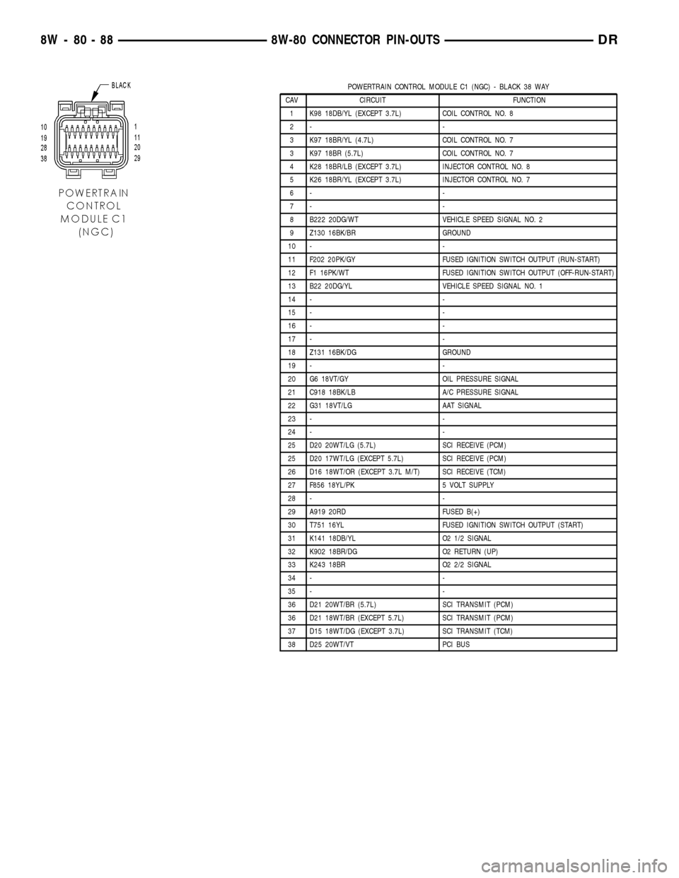
POWERTRAIN CONTROL MODULE C1 (NGC) - BLACK 38 WAY
CAV CIRCUIT FUNCTION
1 K98 18DB/YL (EXCEPT 3.7L) COIL CONTROL NO. 8
2- -
3 K97 18BR/YL (4.7L) COIL CONTROL NO. 7
3 K97 18BR (5.7L) COIL CONTROL NO. 7
4 K28 18BR/LB (EXCEPT 3.7L) INJECTOR CONTROL NO. 8
5 K26 18BR/YL (EXCEPT 3.7L) INJECTOR CONTROL NO. 7
6- -
7- -
8 B222 20DG/WT VEHICLE SPEED SIGNAL NO. 2
9 Z130 16BK/BR GROUND
10 - -
11 F202 20PK/GY FUSED IGNITION SWITCH OUTPUT (RUN-START)
12 F1 16PK/WT FUSED IGNITION SWITCH OUTPUT (OFF-RUN-START)
13 B22 20DG/YL VEHICLE SPEED SIGNAL NO. 1
14 - -
15 - -
16 - -
17 - -
18 Z131 16BK/DG GROUND
19 - -
20 G6 18VT/GY OIL PRESSURE SIGNAL
21 C918 18BK/LB A/C PRESSURE SIGNAL
22 G31 18VT/LG AAT SIGNAL
23 - -
24 - -
25 D20 20WT/LG (5.7L) SCI RECEIVE (PCM)
25 D20 17WT/LG (EXCEPT 5.7L) SCI RECEIVE (PCM)
26 D16 18WT/OR (EXCEPT 3.7L M/T) SCI RECEIVE (TCM)
27 F856 18YL/PK 5 VOLT SUPPLY
28 - -
29 A919 20RD FUSED B(+)
30 T751 16YL FUSED IGNITION SWITCH OUTPUT (START)
31 K141 18DB/YL O2 1/2 SIGNAL
32 K902 18BR/DG O2 RETURN (UP)
33 K243 18BR O2 2/2 SIGNAL
34 - -
35 - -
36 D21 20WT/BR (5.7L) SCI TRANSMIT (PCM)
36 D21 18WT/BR (EXCEPT 5.7L) SCI TRANSMIT (PCM)
37 D15 18WT/DG (EXCEPT 3.7L) SCI TRANSMIT (TCM)
38 D25 20WT/VT PCI BUS
8W - 80 - 88 8W-80 CONNECTOR PIN-OUTSDR
Page 1158 of 2627
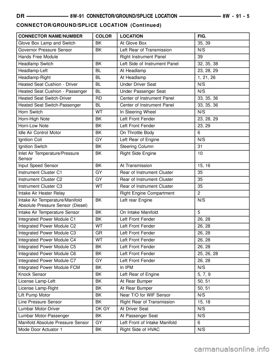
CONNECTOR NAME/NUMBER COLOR LOCATION FIG.
Glove Box Lamp and Switch BK At Glove Box 35, 39
Governor Pressure Sensor BK Left Rear of Transmission N/S
Hands Free Module Right Instrument Panel 39
Headlamp Switch BK Left Side of Instrument Panel 32, 35, 38
Headlamp-Left BL At Headlamp 23, 28, 29
Headlamp-Right BL At Headlamp 1, 21, 26
Heated Seat Cushion - Driver BL Under Driver Seat N/S
Heated Seat Cushion - Passenger BL Under Passenger Seat N/S
Heated Seat Switch-Driver RD Center of Instrument Panel 33, 35, 36
Heated Seat Switch-Passenger BL Center of Instrument Panel 33, 35, 36
Horn Switch WT In Steering Wheel N/S
Horn-High Note BK Left Front Fender 23, 28, 29
Horn-Low Note BK Left Front Fender 23, 29
Idle Air Control Motor BK On Throttle Body 6
Ignition Coil GY Left Rear of Engine N/S
Ignition Switch BK Steering Column 31
Inlet Air Temperature/Pressure
SensorBK Right Side Engine 10
Input Speed Sensor BK At Transmission 15, 16
Instrument Cluster C1 GY Rear of Instrument Cluster 35
Instrument Cluster C2 GY Rear of Instrument Cluster 35
Instrument Cluster C3 WT Rear of Instrument Cluster 35
Intake Air Heater Relay Right Engine Compartment 2
Intake Air Temperature/Manifold
Absolute Pressure Sensor (Diesel)BK Left rear Engine N/S
Intake Air Temperature Sensor BK On Intake Manifold 5
Integrated Power Module C1 BK Left Front Fender 26, 28
Integrated Power Module C2 WT Left Front Fender 26, 28
Integrated Power Module C3 GR Left Front Fender 26, 28
Integrated Power Module C4 WT Left Front Fender 26, 28
Integrated Power Module C5 BK Left Front Fender 26, 28
Integrated Power Module C6 BK Left Front Fender 25, 26, 28
Integrated Power Module C7 GY Left Front Fender 26, 28
Integrated Power Module FCM BK In IPM N/S
Knock Sensor BK Left Rear of Engine 5, 7, 9
License Lamp-Left BK At Rear Bumper 50, 51
License Lamp-Right BK At Rear Bumper 50, 51
Lift Pump Motor BK Near T/O for WIF Sensor N/S
Line Pressure Sensor BK Right Rear of Transmission 15, 18
Lumbar Motor-Driver DK GY At Driver Seat N/S
Lumbar Motor-Passenger BK At Passenger Seat N/S
Manifold Absolute Pressure Sensor GY Left Front of Intake Manifold 6
Mode Door Actuator 1 BK Right Side of HVAC N/S
DR8W-91 CONNECTOR/GROUND/SPLICE LOCATION 8W - 91 - 5
CONNECTOR/GROUND/SPLICE LOCATION (Continued)
Page 1217 of 2627

SPECIAL TOOLS
POWER DISTRIBUTION SYSTEMS
CIGAR LIGHTER OUTLET
DESCRIPTION
On models equipped a cigar lighter outlet is
installed to the left of the center stack area in the
lower instrument panel. The cigar lighter outlet is
secured by a snap fit within the bezel.
The cigar lighter outlet, plastic cap and the knob
and heating element unit are available for service
replacement. These components cannot be repaired
and, if faulty or damaged, they must be replaced.
OPERATION
The cigar lighter consists of two major components:
a knob and heating element unit, and the cigar
lighter base or outlet shell. The receptacle shell is
connected to ground, and an insulated contact in the
bottom of the shell is connected to battery current.
The cigar lighter receives battery voltage from a fuse
in the junction block when the ignition switch is in
the Accessory or Run positions.
The cigar lighter knob and heating element are
encased within a spring-loaded housing, which also
features a sliding protective heat shield. When the
knob and heating element are inserted in the outlet
shell, the heating element resistor coil is grounded
through its housing to the outlet shell. If the cigar
lighter knob is pushed inward, the heat shield slides
up toward the knob exposing the heating element,
and the heating element extends from the housing
toward the insulated contact in the bottom of the
outlet shell.
Two small spring-clip retainers are located on
either side of the insulated contact inside the bottom
of the outlet shell. These clips engage and hold the
heating element against the insulated contact longenough for the resistor coil to heat up. When the
heating element is engaged with the contact, battery
current can flow through the resistor coil to ground,
causing the resistor coil to heat.
When the resistor coil becomes sufficiently heated,
excess heat radiates from the heating element caus-
ing the spring-clips to expand. Once the spring-clips
expand far enough to release the heating element,
the spring-loaded housing forces the knob and heat-
ing element to pop back outward to their relaxed
position. When the cigar lighter knob and element
are pulled out of the outlet shell, the protective heat
shield slides downward on the housing so that the
heating element is recessed and shielded around its
circumference for safety.
DIAGNOSIS AND TESTING - CIGAR LIGHTER
OUTLET
For complete circuit diagrams, refer toWiring
Diagrams.
(1) Check the fused B(+) fuse in the integrated
power module. If OK, go to Step 2. If not OK, repair
the shorted circuit or component as required and
replace the faulty fuse.
(2) Turn the ignition switch to the Run position.
Check for battery voltage at the fused B(+) fuse in
the integrated power module. If OK, go to Step 3. If
not OK, repair the open or short as required.
(3) Remove the cigar lighter knob and element
from the cigar lighter outlet shell. Check for continu-
ity between the inside circumference of the cigar
lighter outlet shell and a good ground. there should
be continuity. If OK, go to Step 4. If not OK, go to
Step 5.
(4) Turn the ignition switch to the Run position.
Check for battery voltage at the insulated contact
located at the back of the cigar lighter outlet shell. If
OK, replace the faulty cigar lighter knob and ele-
ment. If not OK, go to Step 5.
(5) Turn the ignition switch to the Off position.
Disconnect and isolate the battery negative cable.
Check for continuity between the ground circuit cav-
ity of the cigar lighter wire harness connector and a
good ground. There should be continuity. If OK, go to
Step 6. If not OK, repair the open ground circuit to
ground as required.
(6) Connect the battery negative cable. Turn the
ignition switch to the Accessory or Run positions.
Check for battery voltage at the fused B(+) circuit
cavity of the cigar lighter wire harness connector. If
OK, replace the faulty cigar lighter outlet. If not OK,
repair the open fused B(+) circuit to the integrated
power module fuse as required.Terminal Pick Kit 6680
8W - 97 - 2 8W-97 POWER DISTRIBUTIONDR
POWER DISTRIBUTION (Continued)
Page 1227 of 2627
DIAGNOSIS AND TESTING
DIAGNOSIS AND TESTING - ENGINE
DIAGNOSIS - INTRODUCTION
Engine diagnosis is helpful in determining the
causes of malfunctions not detected and remedied by
routine maintenance.
These malfunctions may be classified as either per-
formance (e.g., engine idles rough and stalls) or
mechanical (e.g., a strange noise).
(Refer to 9 - ENGINE - DIAGNOSIS AND TEST-
ING) - PERFORMANCE and (Refer to 9 - ENGINE -
DIAGNOSIS AND TESTING)ÐMECHANICAL for
possible causes and corrections of malfunctions.
(Refer to 14 - FUEL SYSTEM/FUEL DELIVERY -
DIAGNOSIS AND TESTING) and (Refer to 14 -
FUEL SYSTEM/FUEL INJECTION - DIAGNOSIS
AND TESTING) for the fuel system diagnosis.Additional tests and diagnostic procedures may be
necessary for specific engine malfunctions that can
not be isolated with the Service Diagnosis charts.
Information concerning additional tests and diagno-
sis is provided within the following diagnosis:
²Cylinder Compression Pressure Test (Refer to 9 -
ENGINE - DIAGNOSIS AND TESTING).
²Cylinder Combustion Pressure Leakage Test
(Refer to 9 - ENGINE - DIAGNOSIS AND TEST-
ING).
²Engine Cylinder Head Gasket Failure Diagnosis
(Refer to 9 - ENGINE/CYLINDER HEAD - DIAGNO-
SIS AND TESTING).
²Intake Manifold Leakage Diagnosis (Refer to 9 -
ENGINE/MANIFOLDS/INTAKE MANIFOLD -
DIAGNOSIS AND TESTING).
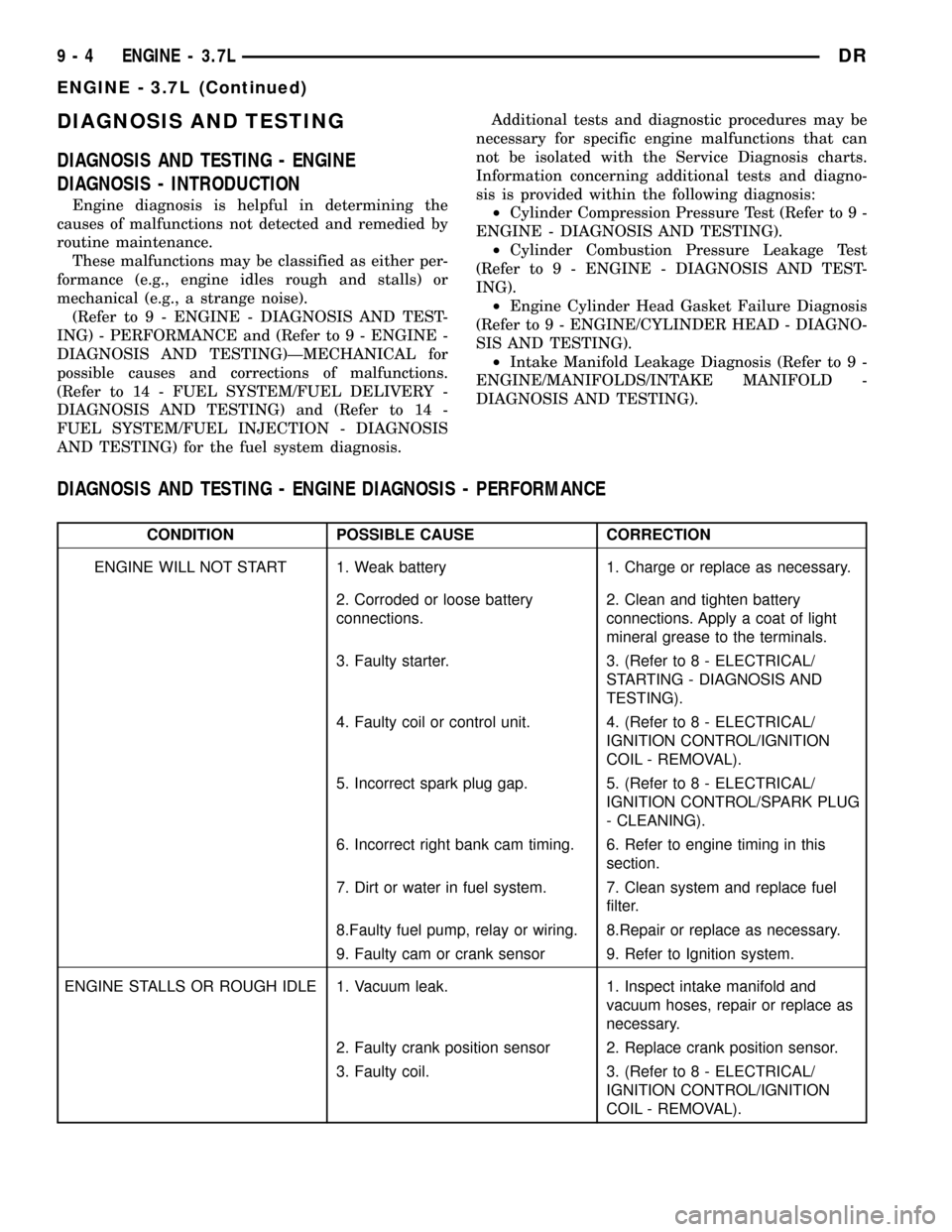
DIAGNOSIS AND TESTING - ENGINE DIAGNOSIS - PERFORMANCE
CONDITION POSSIBLE CAUSE CORRECTION
ENGINE WILL NOT START 1. Weak battery 1. Charge or replace as necessary.
2. Corroded or loose battery
connections.2. Clean and tighten battery
connections. Apply a coat of light
mineral grease to the terminals.
3. Faulty starter. 3. (Refer to 8 - ELECTRICAL/
STARTING - DIAGNOSIS AND
TESTING).
4. Faulty coil or control unit. 4. (Refer to 8 - ELECTRICAL/
IGNITION CONTROL/IGNITION
COIL - REMOVAL).
5. Incorrect spark plug gap. 5. (Refer to 8 - ELECTRICAL/
IGNITION CONTROL/SPARK PLUG
- CLEANING).
6. Incorrect right bank cam timing. 6. Refer to engine timing in this
section.
7. Dirt or water in fuel system. 7. Clean system and replace fuel
filter.
8.Faulty fuel pump, relay or wiring. 8.Repair or replace as necessary.
9. Faulty cam or crank sensor 9. Refer to Ignition system.
ENGINE STALLS OR ROUGH IDLE 1. Vacuum leak. 1. Inspect intake manifold and
vacuum hoses, repair or replace as
necessary.
2. Faulty crank position sensor 2. Replace crank position sensor.
3. Faulty coil. 3. (Refer to 8 - ELECTRICAL/
IGNITION CONTROL/IGNITION
COIL - REMOVAL).
9 - 4 ENGINE - 3.7LDR
ENGINE - 3.7L (Continued)
Page 1228 of 2627
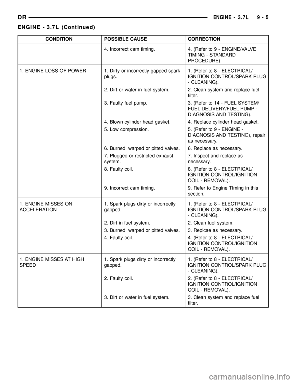
CONDITION POSSIBLE CAUSE CORRECTION
4. Incorrect cam timing. 4. (Refer to 9 - ENGINE/VALVE
TIMING - STANDARD
PROCEDURE).
1. ENGINE LOSS OF POWER 1. Dirty or incorrectly gapped spark
plugs.1. (Refer to 8 - ELECTRICAL/
IGNITION CONTROL/SPARK PLUG
- CLEANING).
2. Dirt or water in fuel system. 2. Clean system and replace fuel
filter.
3. Faulty fuel pump. 3. (Refer to 14 - FUEL SYSTEM/
FUEL DELIVERY/FUEL PUMP -
DIAGNOSIS AND TESTING).
4. Blown cylinder head gasket. 4. Replace cylinder head gasket.
5. Low compression. 5. (Refer to 9 - ENGINE -
DIAGNOSIS AND TESTING), repair
as necessary.
6. Burned, warped or pitted valves. 6. Replace as necessary.
7. Plugged or restricted exhaust
system.7. Inspect and replace as
necessary.
8. Faulty coil. 8. (Refer to 8 - ELECTRICAL/
IGNITION CONTROL/IGNITION
COIL - REMOVAL).
9. Incorrect cam timing. 9. Refer to Engine TIming in this
section.
1. ENGINE MISSES ON
ACCELERATION1. Spark plugs dirty or incorrectly
gapped.1. (Refer to 8 - ELECTRICAL/
IGNITION CONTROL/SPARK PLUG
- CLEANING).
2. Dirt in fuel system. 2. Clean fuel system.
3. Burned, warped or pitted valves. 3. Replcae as necessary.
4. Faulty coil. 4. (Refer to 8 - ELECTRICAL/
IGNITION CONTROL/IGNITION
COIL - REMOVAL).
1. ENGINE MISSES AT HIGH
SPEED1. Spark plugs dirty or incorrectly
gapped.1. (Refer to 8 - ELECTRICAL/
IGNITION CONTROL/SPARK PLUG
- CLEANING).
2. Faulty coil. 2. (Refer to 8 - ELECTRICAL/
IGNITION CONTROL/IGNITION
COIL - REMOVAL).
3. Dirt or water in fuel system. 3. Clean system and replace fuel
filter.
DRENGINE - 3.7L 9 - 5
ENGINE - 3.7L (Continued)
Page 1260 of 2627

CYLINDER HEAD COVER(S)
REMOVAL
(1) Disconnect battery negative cable.
(2) Remove air cleaner assembly, resonator assem-
bly and air inlet hose.
(3) Drain cooling system, below the level of the
heater hoses(Refer to 7 - COOLING - STANDARD
PROCEDURE).
(4)
Remove accessory drive belt(Refer to 7 - COOL-
ING/ACCESSORY DRIVE/DRIVE BELTS - REMOVAL).
(5) Remove air conditioning compressor retaining
bolts and move compressor to the left.
(6) Remove heater hoses.
(7) Disconnect injector and ignition coil connectors.
(8) Disconnect and remove positive crankcase ven-
tilation (PCV) hose.
(9) Remove oil fill tube.
(10) Un-clip injector and ignition coil harness and
move away from cylinder head cover.
(11) Remove right rear breather tube and filter
assembly.
(12) Remove cylinder head cover retaining bolts.
(13) Remove cylinder head cover.
INSTALLATION
CAUTION: Do not use harsh cleaners to clean the
cylinder head covers. Severe damage to covers
may occur.
NOTE: The gasket may be used again, provided no
cuts, tears, or deformation has occurred.
(1) Clean cylinder head cover and both sealing sur-
faces. Inspect and replace gasket as necessary.
(2) Tighten cylinder head cover bolts and double
ended studs to 12 N´m (105 in. lbs).
(3) Install right rear breather tube and filter
assembly.
(4) Connect injector, ignition coil electrical connec-
tors and harness retaining clips.
(5) Install the oil fill tube.
(6) Install PCV hose.
(7) Install heater hoses.
(8) Install air conditioning compressor retaining
bolts.
(9) Install accessory drive belt(Refer to 7 - COOL-
ING/ACCESSORY DRIVE/DRIVE BELTS - INSTAL-
LATION).
(10) Fill Cooling system(Refer to 7 - COOLING -
STANDARD PROCEDURE).
(11) Install air cleaner assembly, resonator assem-
bly and air inlet hose.
(12) Connect battery negative cable.
ROCKER ARM
DESCRIPTION
The rocker arms are steel stampings with an inte-
gral roller bearing. The rocker arms incorporate a 2.8
mm (0.11 inch) oil hole in the lash adjuster socket for
roller and camshaft lubrication.
REMOVAL
NOTE: Disconnect the battery negative cable to pre-
vent accidental starter engagement.
(1) Remove the cylinder head cover (Refer to 9 -
ENGINE/CYLINDER HEAD/CYLINDER HEAD
COVER(S) - REMOVAL).
(2) For rocker arm removal on cylinder No. 4,
Rotate the crankshaft until cylinder No. 1 is at BDC
intake stroke.
(3) For rocker arm removal on cylinder No. 1,
Rotate the crankshaft until cylinder No. 1 is at BDC
combustion stroke.
(4) For rocker arm removal on cylinders No. 3 and
No. 5, Rotate the crankshaft until cylinder No. 1 is at
TDC exhaust stroke.
(5) For rocker arm removal on cylinders No. 2 and
No. 6, Rotate the crankshaft until cylinder No. 1 is at
TDC ignition stroke.
(6) Using special tool 8516 Rocker Arm Remover,
press downward on the valve spring, remove rocker
arm (Fig. 28).
Fig. 28 Rocker Arm - Removal
1 - CAMSHAFT
2 - SPECIAL TOOL 8516
DRENGINE - 3.7L 9 - 37
Page 1296 of 2627

(1) Start the engine.
(2) Spray a small stream of water (spray bottle) at
the suspected leak area.
(3) If engine RPM'S change, the area of the sus-
pected leak has been found.
(4) Repair as required.
REMOVAL
(1) Disconnect negative cable from battery.
(2) Remove resonator assembly and air inlet hose.
(3) Disconnect throttle and speed control cables.
(4) Disconnect electrical connectors for the follow-
ing components: Refer to FUEL SYSTEM for compo-
nent locations.
²Manifold Absolute Pressure (MAP) Sensor
²Intake Air Temperature (IAT) Sensor
²Throttle Position (TPS) Sensor
²Coolant Temperature (CTS) Sensor
²Idle Air Control (IAC) Motor
(5) Disconnect vapor purge hose, brake booster
hose, speed control servo hose, positive crankcase
ventilation (PCV) hose.
(6) Disconnect generator electrical connections.
(7) Disconnect air conditioning compressor electri-
cal connections.
(8) Disconnect left and right radio suppressor
straps.
(9) Disconnect and remove ignition coil towers.
(10) Remove top oil dipstick tube retaining bolt
and ground strap.
(11) Bleed fuel system (Refer to 14 - FUEL SYS-
TEM/FUEL DELIVERY - STANDARD PROCE-
DURE).
(12) Remove fuel rail.
(13) Remove throttle body assembly and mounting
bracket.
(14) Drain cooling system below coolant tempera-
ture level (Refer to 7 - COOLING - STANDARD
PROCEDURE).
(15) Remove the heater hoses from the engine
front cover and the heater core.
(16) Unclip and remove heater hoses and tubes
from intake manifold.
(17) Remove coolant temperature sensor (Refer to
7 - COOLING/ENGINE/ENGINE COOLANT TEMP
SENSOR - REMOVAL).
(18) Remove intake manifold retaining fasteners in
reverse order of tightening sequence.
(19) Remove intake manifold.
INSTALLATION
(1) Install intake manifold gaskets.
(2) Install intake manifold.
(3) Install intake manifold retaining bolts and
tighten in sequence shown in to 12 N´m (105 in. lbs.)
(Fig. 89).(4) Install left and right radio suppressor straps.
(5) Install throttle body assembly.
(6) Connect throttle cable and speed control cable
to throttle body.
(7) Install fuel rail.
(8) Install ignition coil towers.
(9) Position and install heater hoses and tubes
onto intake manifold.
(10) Install the heater hoses to the heater core and
engine front cover.
(11) Connect electrical connectors for the following
components:
²Manifold Absolute Pressure (MAP) Sensor
²Intake Air Temperature (IAT) Sensor
²Throttle Position (TPS) Sensor
²Coolant Temperature (CTS) Sensor
²Idle Air Control (IAC) Motor
²Ignition coil towers
²Fuel injectors
(12) Install top oil dipstick tube retaining bolt and
ground strap.
(13) Connect generator electrical connections.
(14) Connect Vapor purge hose, Brake booster
hose, Speed control servo hose, Positive crankcase
ventilation (PCV) hose.
(15) Fill cooling system (Refer to 7 - COOLING -
STANDARD PROCEDURE).
(16) Install resonator assembly and air inlet hose.
(17) Connect negative cable to battery.
Fig. 89 Intake Manifold Tightening Sequence
DRENGINE - 3.7L 9 - 73
INTAKE MANIFOLD (Continued)
Page 1313 of 2627
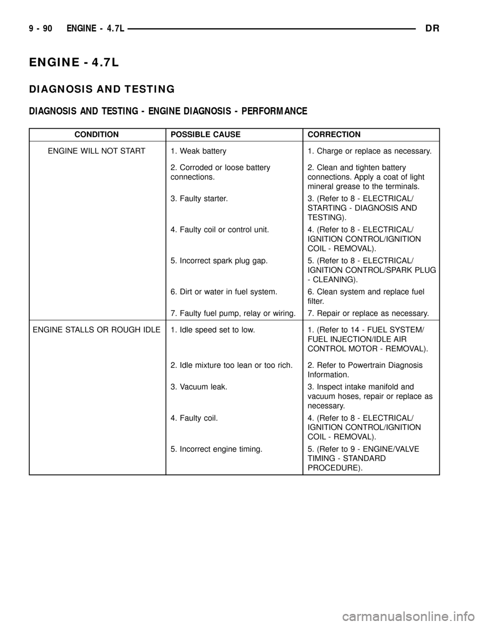
ENGINE - 4.7L
DIAGNOSIS AND TESTING
DIAGNOSIS AND TESTING - ENGINE DIAGNOSIS - PERFORMANCE
CONDITION POSSIBLE CAUSE CORRECTION
ENGINE WILL NOT START 1. Weak battery 1. Charge or replace as necessary.
2. Corroded or loose battery
connections.2. Clean and tighten battery
connections. Apply a coat of light
mineral grease to the terminals.
3. Faulty starter. 3. (Refer to 8 - ELECTRICAL/
STARTING - DIAGNOSIS AND
TESTING).
4. Faulty coil or control unit. 4. (Refer to 8 - ELECTRICAL/
IGNITION CONTROL/IGNITION
COIL - REMOVAL).
5. Incorrect spark plug gap. 5. (Refer to 8 - ELECTRICAL/
IGNITION CONTROL/SPARK PLUG
- CLEANING).
6. Dirt or water in fuel system. 6. Clean system and replace fuel
filter.
7. Faulty fuel pump, relay or wiring. 7. Repair or replace as necessary.
ENGINE STALLS OR ROUGH IDLE 1. Idle speed set to low. 1. (Refer to 14 - FUEL SYSTEM/
FUEL INJECTION/IDLE AIR
CONTROL MOTOR - REMOVAL).
2. Idle mixture too lean or too rich. 2. Refer to Powertrain Diagnosis
Information.
3. Vacuum leak. 3. Inspect intake manifold and
vacuum hoses, repair or replace as
necessary.
4. Faulty coil. 4. (Refer to 8 - ELECTRICAL/
IGNITION CONTROL/IGNITION
COIL - REMOVAL).
5. Incorrect engine timing. 5. (Refer to 9 - ENGINE/VALVE
TIMING - STANDARD
PROCEDURE).
9 - 90 ENGINE - 4.7LDR