Intake removal DODGE RAM 1500 1998 2.G Owner's Guide
[x] Cancel search | Manufacturer: DODGE, Model Year: 1998, Model line: RAM 1500, Model: DODGE RAM 1500 1998 2.GPages: 2627
Page 1261 of 2627
VALVE GUIDE SEALS
DESCRIPTION
The valve guide seals are made of rubber and
incorporate an integral steel valve spring seat. The
integral garter spring maintains consistent lubrica-
tion control to the valve stems.
VALVE SPRINGS
DESCRIPTION
The valve springs are made from high strength
chrome silicon steel. There are different springs for
intake and exhaust applications. The exhaust spring
has an external damper. The valve spring seat is
integral with the valve stem seal, which is a positive
type seal to control lubrication.
REMOVAL
(1) Remove the cylinder head cover(Refer to 9 -
ENGINE/CYLINDER HEAD/CYLINDER HEAD
COVER(S) - REMOVAL).
(2) Using Special Tool 8516 Valve Spring Compres-
sor, remove the rocker arms and the hydraulic lash
adjusters.
(3) Remove the spark plug for the cylinder the
valve spring and seal are to be removed from.
(4) Apply shop air to the cylinder to hold the
valves in place when the spring is removed.
NOTE: All six valve springs and seals are removed
in the same manner; this procedure only covers
one valve seal and valve spring.
(5) Using Special Tool 8387 Valve Spring Compres-
sor, compress the valve spring.
NOTE: It may be necessary to tap the top of the
valve spring to loosen the spring retainers locks
enough to be removed.
(6) Remove the two spring retainer lock halves.
NOTE: the valve spring is under tension use care
when releasing the valve spring compressor.
(7) Remove the valve spring compressor.
NOTE: The valve springs are NOT common between
intake and exhaust.
(8) Remove the spring retainer, and the spring.
(9) Remove the valve stem seal.
NOTE: The valve stem seals are common between
intake and exhaust.
INSTALLATION
NOTE: All six valve springs and seals are removed
in the same manner; this procedure only covers
one valve seal and valve spring.
(1) Apply shop air to the cylinder to hold the
valves in place while the spring is installed.
NOTE: The valve stem seals are common between
intake and exhaust.
(2) Install the valve stem seal.
NOTE: The valve springs are NOT common between
intake and exhaust.
(3) Install the spring retainer, and the spring.
(4) Using Special Tool 8387 Valve Spring Compres-
sor, compress the valve spring.
(5) Install the two spring retainer lock halves.
NOTE: the valve spring is under tension use care
when releasing the valve spring compressor.
(6) Remove the valve spring compressor.
(7) Disconnect the shop air to the cylinder.
(8) Install the spark plug for the cylinder the valve
spring and seal was installed on.
(9) Using Special Tool 8516 Valve Spring Compres-
sor, install the rocker arms and the hydraulic lash
adjusters.
(10) Install the cylinder head cover(Refer to 9 -
ENGINE/CYLINDER HEAD/CYLINDER HEAD
COVER(S) - INSTALLATION).
ENGINE BLOCK
DESCRIPTION
The cylinder block is made of cast iron. The block
is a closed deck design with the left bank forward. To
provide high rigidity and improved NVH an
enhanced compacted graphite bedplate is bolted to
the block. The block design allows coolant flow
between the cylinders bores, and an internal coolant
bypass to a single poppet inlet thermostat is included
in the cast aluminum front cover.
STANDARD PROCEDURE - CYLINDER BORE
HONING
Before honing, stuff plenty of clean shop towels
under the bores and over the crankshaft to keep
abrasive materials from entering the crankshaft
area.
(1) Used carefully, the Cylinder Bore Sizing Hone
C-823, equipped with 220 grit stones, is the best tool
9 - 38 ENGINE - 3.7LDR
Page 1284 of 2627
REAR MOUNT
REMOVAL
(1) Raise the vehicle on a hoist.
(2) Using a suitable jack, support transmission.
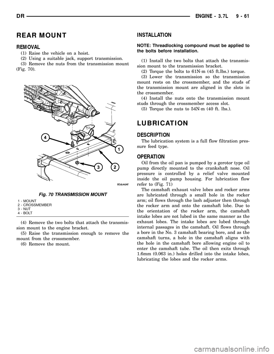
(3) Remove the nuts from the transmission mount
(Fig. 70).
(4) Remove the two bolts that attach the transmis-
sion mount to the engine bracket.
(5) Raise the transmission enough to remove the
mount from the crossmember.
(6) Remove the mount.
INSTALLATION
NOTE: Threadlocking compound must be applied to
the bolts before installation.
(1) Install the two bolts that attach the transmis-
sion mount to the transmission bracket.
(2) Torque the bolts to 61N´m (45 ft.lbs.) torque.
(3) Lower the transmission so the transmission
mount rests on the crossmember, and the studs of
the transmission mount are aligned in the slots in
the crossmember.
(4) Install the nuts onto the transmission mount
studs through the crossmember access slot.
(5) Torque the nuts to 54N´m (40 ft. lbs.).
LUBRICATION
DESCRIPTION
The lubrication system is a full flow filtration pres-
sure feed type.
OPERATION
Oil from the oil pan is pumped by a gerotor type oil
pump directly mounted to the crankshaft nose. Oil
pressure is controlled by a relief valve mounted
inside the oil pump housing. For lubrication flow
refer to (Fig. 71)
The camshaft exhaust valve lobes and rocker arms
are lubricated through a small hole in the rocker
arm; oil flows through the lash adjuster then through
the rocker arm and onto the camshaft lobe. Due to
the orientation of the rocker arm, the camshaft
intake lobes are not lubed in the same manner as the
exhaust lobes. The intake lobes are lubed through
internal passages in the camshaft. Oil flows through
a bore in the No. 3 camshaft bearing bore, and as the
camshaft turns, a hole in the camshaft aligns with
the hole in the camshaft bore allowing engine oil to
enter the camshaft tube. The oil then exits through
1.6mm (0.063 in.) holes drilled into the intake lobes,
lubricating the lobes and the rocker arms.
Fig. 70 TRANSMISSION MOUNT
1 - MOUNT
2 - CROSSMEMBER
3 - NUT
4 - BOLT
DRENGINE - 3.7L 9 - 61
Page 1289 of 2627
OIL PAN
DESCRIPTION
The engine oil pan is made of laminated steel and
has a single plane sealing surface. The sandwich
style oil pan gasket has an integrated windage tray
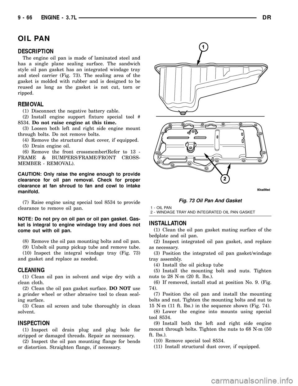
and steel carrier (Fig. 73). The sealing area of the
gasket is molded with rubber and is designed to be
reused as long as the gasket is not cut, torn or
ripped.
REMOVAL
(1) Disconnect the negative battery cable.
(2) Install engine support fixture special tool #
8534.Do not raise engine at this time.
(3) Loosen both left and right side engine mount
through bolts. Do not remove bolts.
(4) Remove the structural dust cover, if equipped.
(5) Drain engine oil.
(6) Remove the front crossmember(Refer to 13 -
FRAME & BUMPERS/FRAME/FRONT CROSS-
MEMBER - REMOVAL).
CAUTION: Only raise the engine enough to provide
clearance for oil pan removal. Check for proper
clearance at fan shroud to fan and cowl to intake
manifold.
(7) Raise engine using special tool 8534 to provide
clearance to remove oil pan.
NOTE: Do not pry on oil pan or oil pan gasket. Gas-
ket is integral to engine windage tray and does not
come out with oil pan.
(8) Remove the oil pan mounting bolts and oil pan.
(9) Unbolt oil pump pickup tube and remove tube.
(10) Inspect the integral windage tray (Fig. 73)
and gasket and replace as needed.
CLEANING
(1) Clean oil pan in solvent and wipe dry with a
clean cloth.
(2) Clean the oil pan gasket surface.DO NOTuse
a grinder wheel or other abrasive tool to clean seal-
ing surface.
(3) Clean oil screen and tube thoroughly in clean
solvent.
INSPECTION
(1) Inspect oil drain plug and plug hole for
stripped or damaged threads. Repair as necessary.
(2) Inspect the oil pan mounting flange for bends
or distortion. Straighten flange, if necessary.
INSTALLATION
(1) Clean the oil pan gasket mating surface of the
bedplate and oil pan.
(2) Inspect integrated oil pan gasket, and replace
as necessary.
(3) Position the integrated oil pan gasket/windage
tray assembly.
(4) Install the oil pickup tube
(5) Install the mounting bolt and nuts. Tighten
nuts to 28 N´m (20 ft. lbs.).
(6) If removed, install stud at position No. 9. (Fig.
74).
(7) Position the oil pan and install the mounting
bolts and nut. Tighten the mounting bolts and nut to
15 N´m (11 ft. lbs.) in the sequence shown (Fig. 74).
(8) Lower the engine into mounts using special
tool 8534.
(9) Install both the left and right side engine
mount through bolts. Tighten the nuts to 68 N´m (50
ft. lbs.).
(10) Remove special tool 8534.
(11) Install structural dust cover, if equipped.
Fig. 73 Oil Pan And Gasket
1 - OIL PAN
2 - WINDAGE TRAY AND INTEGRATED OIL PAN GASKET
9 - 66 ENGINE - 3.7LDR
Page 1296 of 2627
(1) Start the engine.
(2) Spray a small stream of water (spray bottle) at
the suspected leak area.
(3) If engine RPM'S change, the area of the sus-
pected leak has been found.
(4) Repair as required.
REMOVAL
(1) Disconnect negative cable from battery.
(2) Remove resonator assembly and air inlet hose.
(3) Disconnect throttle and speed control cables.
(4) Disconnect electrical connectors for the follow-
ing components: Refer to FUEL SYSTEM for compo-
nent locations.
²Manifold Absolute Pressure (MAP) Sensor
²Intake Air Temperature (IAT) Sensor
²Throttle Position (TPS) Sensor
²Coolant Temperature (CTS) Sensor
²Idle Air Control (IAC) Motor
(5) Disconnect vapor purge hose, brake booster
hose, speed control servo hose, positive crankcase
ventilation (PCV) hose.
(6) Disconnect generator electrical connections.
(7) Disconnect air conditioning compressor electri-
cal connections.
(8) Disconnect left and right radio suppressor
straps.
(9) Disconnect and remove ignition coil towers.
(10) Remove top oil dipstick tube retaining bolt
and ground strap.
(11) Bleed fuel system (Refer to 14 - FUEL SYS-
TEM/FUEL DELIVERY - STANDARD PROCE-
DURE).
(12) Remove fuel rail.
(13) Remove throttle body assembly and mounting
bracket.
(14) Drain cooling system below coolant tempera-
ture level (Refer to 7 - COOLING - STANDARD
PROCEDURE).
(15) Remove the heater hoses from the engine
front cover and the heater core.
(16) Unclip and remove heater hoses and tubes
from intake manifold.
(17) Remove coolant temperature sensor (Refer to
7 - COOLING/ENGINE/ENGINE COOLANT TEMP
SENSOR - REMOVAL).
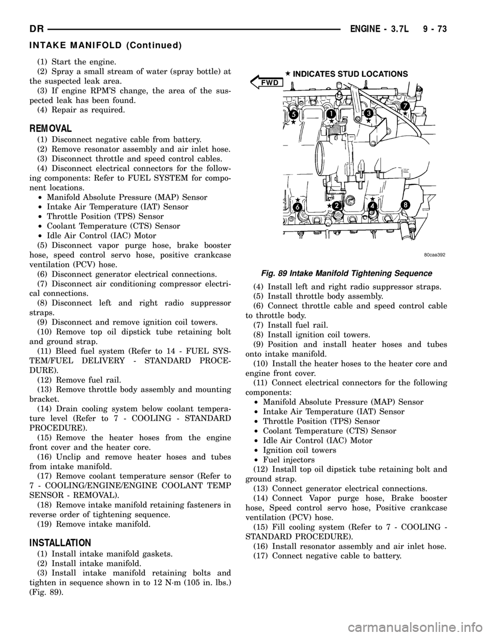
(18) Remove intake manifold retaining fasteners in
reverse order of tightening sequence.
(19) Remove intake manifold.
INSTALLATION
(1) Install intake manifold gaskets.
(2) Install intake manifold.
(3) Install intake manifold retaining bolts and
tighten in sequence shown in to 12 N´m (105 in. lbs.)
(Fig. 89).(4) Install left and right radio suppressor straps.
(5) Install throttle body assembly.
(6) Connect throttle cable and speed control cable
to throttle body.
(7) Install fuel rail.
(8) Install ignition coil towers.
(9) Position and install heater hoses and tubes
onto intake manifold.
(10) Install the heater hoses to the heater core and
engine front cover.
(11) Connect electrical connectors for the following
components:
²Manifold Absolute Pressure (MAP) Sensor
²Intake Air Temperature (IAT) Sensor
²Throttle Position (TPS) Sensor
²Coolant Temperature (CTS) Sensor
²Idle Air Control (IAC) Motor
²Ignition coil towers
²Fuel injectors
(12) Install top oil dipstick tube retaining bolt and
ground strap.
(13) Connect generator electrical connections.
(14) Connect Vapor purge hose, Brake booster
hose, Speed control servo hose, Positive crankcase
ventilation (PCV) hose.
(15) Fill cooling system (Refer to 7 - COOLING -
STANDARD PROCEDURE).
(16) Install resonator assembly and air inlet hose.
(17) Connect negative cable to battery.
Fig. 89 Intake Manifold Tightening Sequence
DRENGINE - 3.7L 9 - 73
INTAKE MANIFOLD (Continued)
Page 1307 of 2627
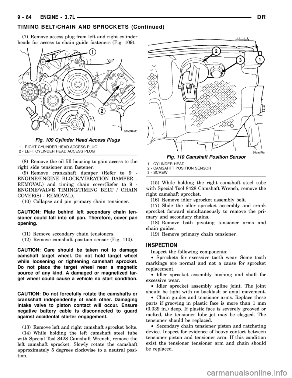
(7) Remove access plug from left and right cylinder
heads for access to chain guide fasteners (Fig. 109).
(8) Remove the oil fill housing to gain access to the
right side tensioner arm fastener.
(9) Remove crankshaft damper (Refer to 9 -
ENGINE/ENGINE BLOCK/VIBRATION DAMPER -
REMOVAL) and timing chain cover(Refer to 9 -
ENGINE/VALVE TIMING/TIMING BELT / CHAIN
COVER(S) - REMOVAL).
(10) Collapse and pin primary chain tensioner.
CAUTION: Plate behind left secondary chain ten-
sioner could fall into oil pan. Therefore, cover pan
opening.
(11) Remove secondary chain tensioners.
(12) Remove camshaft position sensor (Fig. 110).
CAUTION: Care should be taken not to damage
camshaft target wheel. Do not hold target wheel
while loosening or tightening camshaft sprocket.
Do not place the target wheel near a magnetic
source of any kind. A damaged or magnetized tar-
get wheel could cause a vehicle no start condition.
CAUTION: Do not forcefully rotate the camshafts or
crankshaft independently of each other. Damaging
intake valve to piston contact will occur. Ensure
negative battery cable is disconnected to guard
against accidental starter engagement.
(13) Remove left and right camshaft sprocket bolts.
(14) While holding the left camshaft steel tube
with Special Tool 8428 Camshaft Wrench, remove the
left camshaft sprocket. Slowly rotate the camshaft
approximately 5 degrees clockwise to a neutral posi-
tion.(15) While holding the right camshaft steel tube
with Special Tool 8428 Camshaft Wrench, remove the
right camshaft sprocket.
(16) Remove idler sprocket assembly bolt.
(17) Slide the idler sprocket assembly and crank
sprocket forward simultaneously to remove the pri-
mary and secondary chains.
(18) Remove both pivoting tensioner arms and
chain guides.
(19) Remove primary chain tensioner.
INSPECTION
Inspect the following components:
²Sprockets for excessive tooth wear. Some tooth
markings are normal and not a cause for sprocket
replacement.
²Idler sprocket assembly bushing and shaft for
excessive wear.
²Idler sprocket assembly spline joint. The joint
should be tight with no backlash or axial movement.
²Chain guides and tensioner arms. Replace these
parts if grooving in plastic face is more than 1 mm
(0.039 in.) deep. If plastic face is severely grooved or
melted, the tensioner lube jet may be clogged. The
tensioner should be replaced.
²Secondary chain tensioner piston and ratcheting
device. Inspect for evidence of heavy contact between
tensioner piston and tensioner arm. If this condition
exist the tensioner tensioner arm and chain should
be replaced.
Fig. 109 Cylinder Head Access Plugs
1 - RIGHT CYLINDER HEAD ACCESS PLUG
2 - LEFT CYLINDER HEAD ACCESS PLUG
Fig. 110 Camshaft Position Sensor
1 - CYLINDER HEAD
2 - CAMSAHFT POSITION SENSOR
3 - SCREW
9 - 84 ENGINE - 3.7LDR
TIMING BELT/CHAIN AND SPROCKETS (Continued)
Page 1311 of 2627
ENGINE - 4.7L
TABLE OF CONTENTS
page page
ENGINE - 4.7L
DIAGNOSIS AND TESTING
DIAGNOSIS AND TESTING - ENGINE
DIAGNOSIS - PERFORMANCE...........90
DIAGNOSIS AND TESTING - ENGINE
DIAGNOSIS - MECHANICAL.............92
DIAGNOSIS AND TESTING - CYLINDER
COMPRESSION PRESSURE.............93
DIAGNOSIS AND TESTING - CYLINDER
COMBUSTION PRESSURE LEAKAGE......93
DIAGNOSIS AND TESTING - ENGINE
DIAGNOSIS - INTRODUCTION...........94
STANDARD PROCEDURE
STANDARD PROCEDURE - REPAIR
DAMAGED OR WORN THREADS.........94
STANDARD PROCEDURE - FORM-IN-
PLACE GASKETS AND SEALERS.........94
REMOVAL.............................95
INSTALLATION.........................97
SPECIFICATIONS
SPECIFICATIONS - 4.7L ENGINE.........99
TORQUE...........................102
SPECIAL TOOLS
4.7L ENGINE........................103
AIR CLEANER ELEMENT
REMOVAL............................107
INSTALLATION........................107
CYLINDER HEAD
DESCRIPTION
DESCRIPTION - CYLINDER HEAD.......107
DESCRIPTION - VALVE GUIDES.........107
REMOVAL
REMOVAL - LEFT CYLINDER HEAD......108
REMOVAL - RIGHT CYLINDER HEAD.....110
CLEANING...........................111
INSPECTION..........................111
INSTALLATION
INSTALLATION - LEFT CYLINDER HEAD . . . 112
INSTALLATION - RIGHT CYLINDER HEAD . 113
CAMSHAFT(S) - LEFT
DESCRIPTION........................114
REMOVAL............................115
INSTALLATION........................116
CAMSHAFT(S) - RIGHT
DESCRIPTION........................119
REMOVAL............................119
INSTALLATION........................120
CYLINDER HEAD COVER(S)
DESCRIPTION........................122REMOVAL
REMOVAL - RIGHT SIDE...............122
REMOVAL - LEFT SIDE................122
CLEANING...........................123
INSTALLATION
INSTALLATION - RIGHT SIDE...........123
INSTALLATIONÐLEFT SIDE............123
INTAKE/EXHAUST VALVES & SEATS
DESCRIPTION........................123
REMOVAL............................124
INSTALLATION........................124
ROCKER ARM / ADJUSTER ASSEMBLY
DESCRIPTION........................125
DIAGNOSIS AND TESTING - HYDRAULIC
LASH ADJUSTER.....................125
REMOVAL............................126
INSTALLATION........................126
VALVE SPRINGS
DESCRIPTION........................126
REMOVAL............................126
INSTALLATION........................127
VALVE STEM SEALS
DESCRIPTION........................127
ENGINE BLOCK
DESCRIPTION........................128
STANDARD PROCEDURE - CYLINDER BORE
HONING...........................128
CLEANING...........................128
INSPECTION.........................128
CONNECTING ROD BEARINGS
STANDARD PROCEDURE - CONNECTING
ROD BEARING FITTING...............129
CORE PLUGS
REMOVAL............................131
INSTALLATION........................131
CRANKSHAFT
DESCRIPTION........................131
REMOVAL............................131
INSPECTION.........................132
INSTALLATION........................132
CRANKSHAFT MAIN BEARINGS
STANDARD PROCEDUREÐCRANKSHAFT
MAIN BEARING - FITTING..............134
INSPECTION.........................135
CRANKSHAFT OIL SEAL - FRONT
REMOVAL............................135
INSTALLATION........................136
9 - 88 ENGINE - 4.7LDR
Page 1312 of 2627
CRANKSHAFT OIL SEAL - REAR
DIAGNOSIS AND TESTING - REAR SEAL
AREA LEAKS........................137
REMOVAL............................137
INSTALLATION........................138
FLEX PLATE
REMOVAL............................138
INSTALLATION........................138
PISTON & CONNECTING ROD
DESCRIPTION........................139
STANDARD PROCEDURE - PISTON FITTING . 139
REMOVAL............................139
CLEANING...........................140
INSPECTION.........................140
INSTALLATION........................140
PISTON RINGS
STANDARD PROCEDURE - PISTON RING
FITTING............................142
VIBRATION DAMPER
REMOVAL............................144
INSTALLATION........................144
STRUCTURAL COVER
DESCRIPTION........................145
OPERATION..........................145
REMOVAL............................145
INSTALLATION........................145
FRONT MOUNT
REMOVAL............................146
INSTALLATION........................147
REAR MOUNT
REMOVAL............................149
INSTALLATION........................149
LUBRICATION
DESCRIPTION........................150
OPERATION..........................150
DIAGNOSIS AND TESTING
DIAGNOSIS AND TESTING - CHECKING
ENGINE OIL PRESSURE...............152
DIAGNOSIS AND TESTING - ENGINE OIL
LEAK..............................152
OIL
STANDARD PROCEDURE - ENGINE OIL
SERVICE...........................153
OIL FILTER
REMOVAL............................154
INSTALLATION........................155
OIL PAN
REMOVAL............................155
INSTALLATION........................155OIL PRESSURE SENSOR/SWITCH
DESCRIPTION
DESCRIPTION.......................156
DESCRIPTION.......................156
OPERATION
OPERATION........................156
OPERATION........................156
REMOVAL............................156
INSTALLATION........................156
OIL PUMP
REMOVAL............................156
DISASSEMBLY........................157
CLEANING...........................157
INSPECTION.........................157
ASSEMBLY...........................158
INSTALLATION........................159
INTAKE MANIFOLD
DESCRIPTION........................159
DIAGNOSIS AND TESTINGÐINTAKE
MANIFOLD LEAKAGE.................159
REMOVAL............................159
CLEANING...........................160
INSPECTION.........................160
INSTALLATION........................160
EXHAUST MANIFOLD
DESCRIPTION........................161
REMOVAL............................161
CLEANING...........................163
INSPECTION.........................163
INSTALLATION........................164
VALVE TIMING
DESCRIPTIONÐTIMING DRIVE SYSTEM....166
OPERATION - TIMING DRIVE SYSTEM.....166
STANDARD PROCEDURE
STANDARD PROCEDUREÐMEASURING
TIMING CHAIN WEAR.................167
STANDARD PROCEDURE - ENGINE TIMING
- VERIFICATION.....................167
TIMING BELT / CHAIN COVER(S)
REMOVAL............................170
INSTALLATION........................171
TIMING BELT/CHAIN AND SPROCKETS
REMOVAL............................172
INSPECTION.........................174
INSTALLATION........................176
IDLER SHAFT
REMOVAL............................179
INSTALLATION........................179
DRENGINE - 4.7L 9 - 89
Page 1313 of 2627
ENGINE - 4.7L
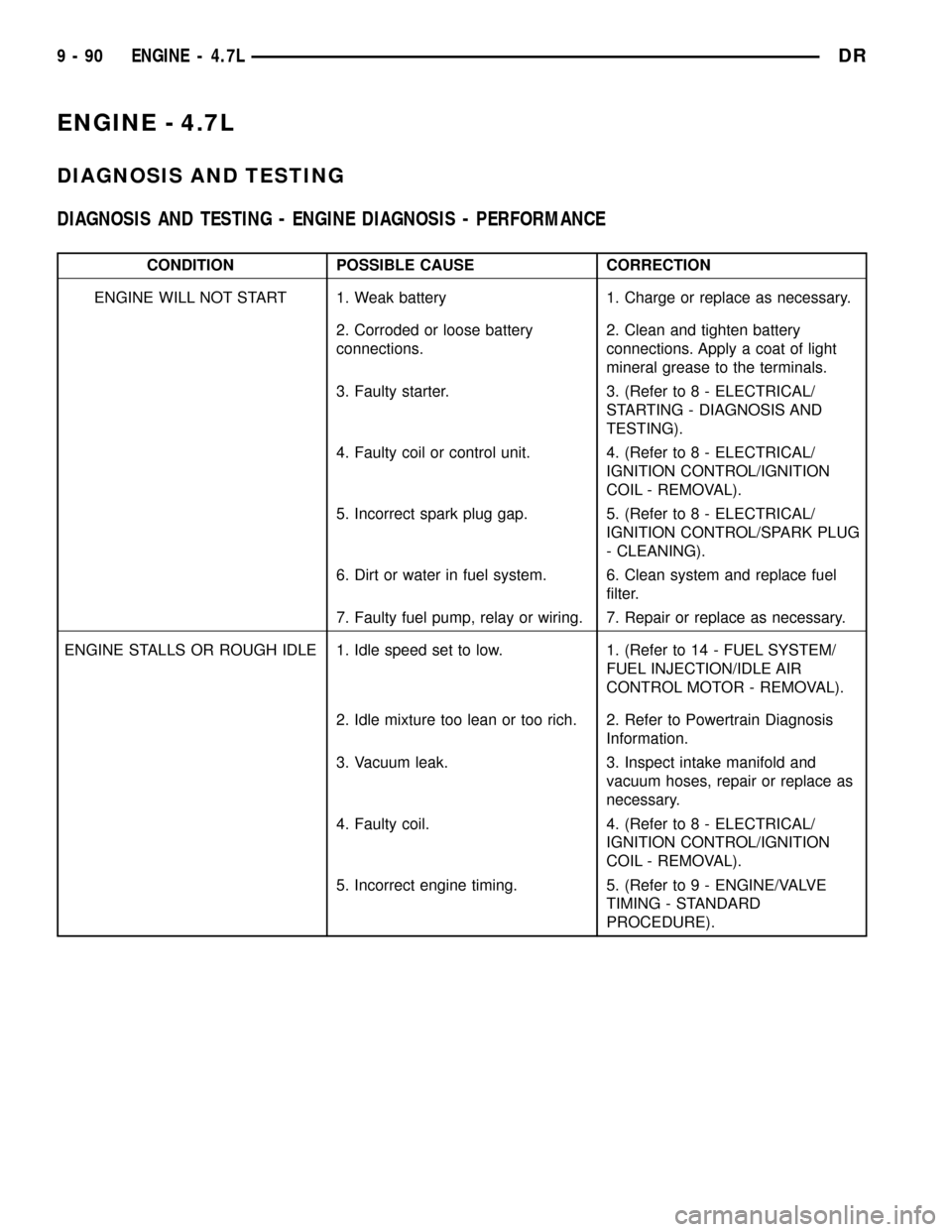
DIAGNOSIS AND TESTING
DIAGNOSIS AND TESTING - ENGINE DIAGNOSIS - PERFORMANCE
CONDITION POSSIBLE CAUSE CORRECTION
ENGINE WILL NOT START 1. Weak battery 1. Charge or replace as necessary.
2. Corroded or loose battery
connections.2. Clean and tighten battery
connections. Apply a coat of light
mineral grease to the terminals.
3. Faulty starter. 3. (Refer to 8 - ELECTRICAL/
STARTING - DIAGNOSIS AND
TESTING).
4. Faulty coil or control unit. 4. (Refer to 8 - ELECTRICAL/
IGNITION CONTROL/IGNITION
COIL - REMOVAL).
5. Incorrect spark plug gap. 5. (Refer to 8 - ELECTRICAL/
IGNITION CONTROL/SPARK PLUG
- CLEANING).
6. Dirt or water in fuel system. 6. Clean system and replace fuel
filter.
7. Faulty fuel pump, relay or wiring. 7. Repair or replace as necessary.
ENGINE STALLS OR ROUGH IDLE 1. Idle speed set to low. 1. (Refer to 14 - FUEL SYSTEM/
FUEL INJECTION/IDLE AIR
CONTROL MOTOR - REMOVAL).
2. Idle mixture too lean or too rich. 2. Refer to Powertrain Diagnosis
Information.
3. Vacuum leak. 3. Inspect intake manifold and
vacuum hoses, repair or replace as
necessary.
4. Faulty coil. 4. (Refer to 8 - ELECTRICAL/
IGNITION CONTROL/IGNITION
COIL - REMOVAL).
5. Incorrect engine timing. 5. (Refer to 9 - ENGINE/VALVE
TIMING - STANDARD
PROCEDURE).
9 - 90 ENGINE - 4.7LDR
Page 1316 of 2627
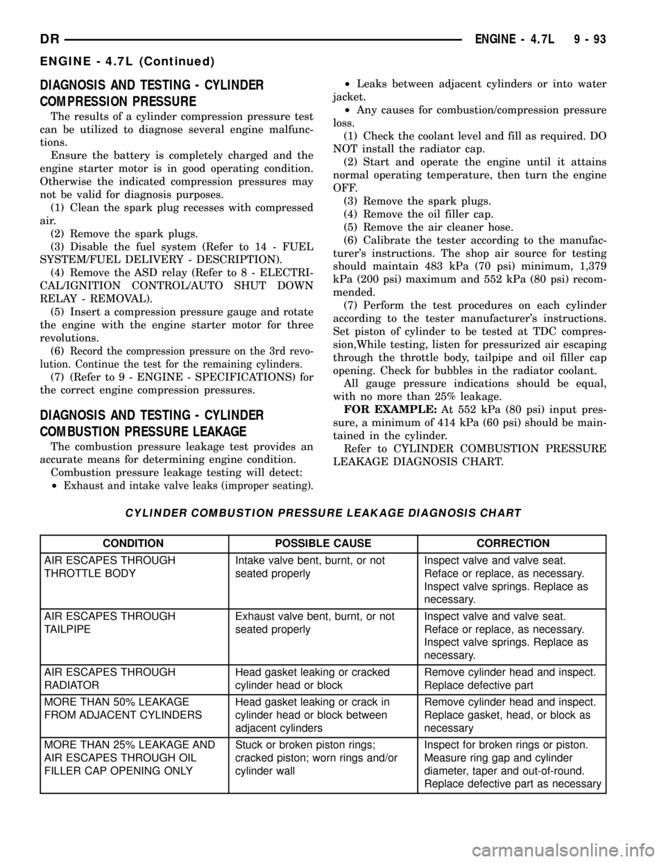
DIAGNOSIS AND TESTING - CYLINDER
COMPRESSION PRESSURE
The results of a cylinder compression pressure test
can be utilized to diagnose several engine malfunc-
tions.
Ensure the battery is completely charged and the
engine starter motor is in good operating condition.
Otherwise the indicated compression pressures may
not be valid for diagnosis purposes.
(1) Clean the spark plug recesses with compressed
air.
(2) Remove the spark plugs.
(3) Disable the fuel system (Refer to 14 - FUEL
SYSTEM/FUEL DELIVERY - DESCRIPTION).
(4) Remove the ASD relay (Refer to 8 - ELECTRI-
CAL/IGNITION CONTROL/AUTO SHUT DOWN
RELAY - REMOVAL).
(5) Insert a compression pressure gauge and rotate
the engine with the engine starter motor for three
revolutions.
(6)
Record the compression pressure on the 3rd revo-
lution. Continue the test for the remaining cylinders.
(7) (Refer to 9 - ENGINE - SPECIFICATIONS) for
the correct engine compression pressures.
DIAGNOSIS AND TESTING - CYLINDER
COMBUSTION PRESSURE LEAKAGE
The combustion pressure leakage test provides an
accurate means for determining engine condition.
Combustion pressure leakage testing will detect:
²
Exhaust and intake valve leaks (improper seating).
²Leaks between adjacent cylinders or into water
jacket.
²Any causes for combustion/compression pressure
loss.
(1) Check the coolant level and fill as required. DO
NOT install the radiator cap.
(2) Start and operate the engine until it attains
normal operating temperature, then turn the engine
OFF.
(3) Remove the spark plugs.
(4) Remove the oil filler cap.
(5) Remove the air cleaner hose.
(6) Calibrate the tester according to the manufac-
turer's instructions. The shop air source for testing
should maintain 483 kPa (70 psi) minimum, 1,379
kPa (200 psi) maximum and 552 kPa (80 psi) recom-
mended.
(7) Perform the test procedures on each cylinder
according to the tester manufacturer's instructions.
Set piston of cylinder to be tested at TDC compres-
sion,While testing, listen for pressurized air escaping
through the throttle body, tailpipe and oil filler cap
opening. Check for bubbles in the radiator coolant.
All gauge pressure indications should be equal,
with no more than 25% leakage.
FOR EXAMPLE:At 552 kPa (80 psi) input pres-
sure, a minimum of 414 kPa (60 psi) should be main-
tained in the cylinder.
Refer to CYLINDER COMBUSTION PRESSURE
LEAKAGE DIAGNOSIS CHART.
CYLINDER COMBUSTION PRESSURE LEAKAGE DIAGNOSIS CHART
CONDITION POSSIBLE CAUSE CORRECTION
AIR ESCAPES THROUGH
THROTTLE BODYIntake valve bent, burnt, or not
seated properlyInspect valve and valve seat.
Reface or replace, as necessary.
Inspect valve springs. Replace as
necessary.
AIR ESCAPES THROUGH
TAILPIPEExhaust valve bent, burnt, or not
seated properlyInspect valve and valve seat.
Reface or replace, as necessary.
Inspect valve springs. Replace as
necessary.
AIR ESCAPES THROUGH
RADIATORHead gasket leaking or cracked
cylinder head or blockRemove cylinder head and inspect.
Replace defective part
MORE THAN 50% LEAKAGE
FROM ADJACENT CYLINDERSHead gasket leaking or crack in
cylinder head or block between
adjacent cylindersRemove cylinder head and inspect.
Replace gasket, head, or block as
necessary
MORE THAN 25% LEAKAGE AND
AIR ESCAPES THROUGH OIL
FILLER CAP OPENING ONLYStuck or broken piston rings;
cracked piston; worn rings and/or
cylinder wallInspect for broken rings or piston.
Measure ring gap and cylinder
diameter, taper and out-of-round.
Replace defective part as necessary
DRENGINE - 4.7L 9 - 93
ENGINE - 4.7L (Continued)
Page 1319 of 2627
(19) Disconnect throttle and speed control cables.
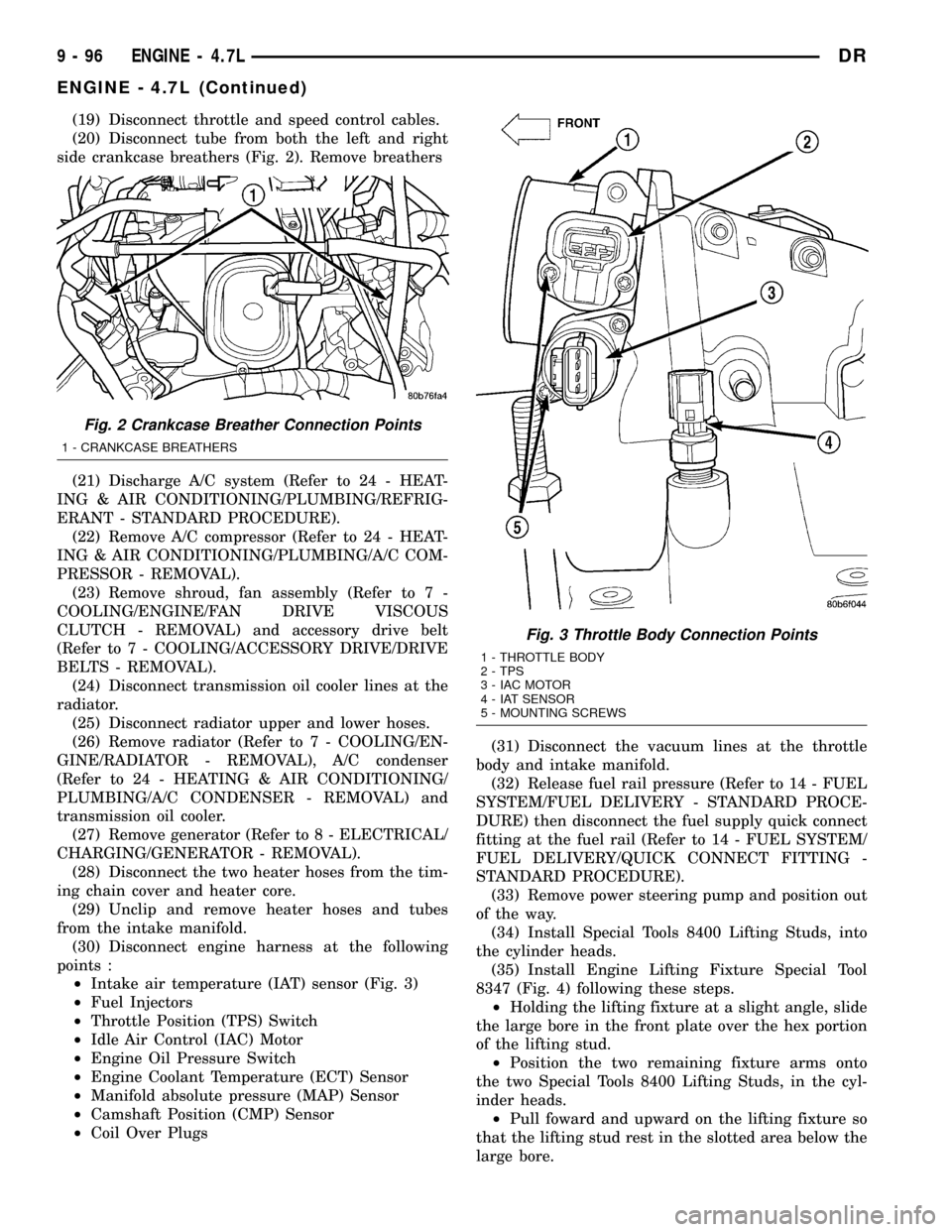
(20) Disconnect tube from both the left and right
side crankcase breathers (Fig. 2). Remove breathers
(21) Discharge A/C system (Refer to 24 - HEAT-
ING & AIR CONDITIONING/PLUMBING/REFRIG-
ERANT - STANDARD PROCEDURE).
(22) Remove A/C compressor (Refer to 24 - HEAT-
ING & AIR CONDITIONING/PLUMBING/A/C COM-
PRESSOR - REMOVAL).
(23) Remove shroud, fan assembly (Refer to 7 -
COOLING/ENGINE/FAN DRIVE VISCOUS
CLUTCH - REMOVAL) and accessory drive belt
(Refer to 7 - COOLING/ACCESSORY DRIVE/DRIVE
BELTS - REMOVAL).
(24) Disconnect transmission oil cooler lines at the
radiator.
(25) Disconnect radiator upper and lower hoses.
(26) Remove radiator (Refer to 7 - COOLING/EN-
GINE/RADIATOR - REMOVAL), A/C condenser
(Refer to 24 - HEATING & AIR CONDITIONING/
PLUMBING/A/C CONDENSER - REMOVAL) and
transmission oil cooler.
(27) Remove generator (Refer to 8 - ELECTRICAL/
CHARGING/GENERATOR - REMOVAL).
(28) Disconnect the two heater hoses from the tim-
ing chain cover and heater core.
(29) Unclip and remove heater hoses and tubes
from the intake manifold.
(30) Disconnect engine harness at the following
points :
²Intake air temperature (IAT) sensor (Fig. 3)
²Fuel Injectors
²Throttle Position (TPS) Switch
²Idle Air Control (IAC) Motor
²Engine Oil Pressure Switch
²Engine Coolant Temperature (ECT) Sensor
²Manifold absolute pressure (MAP) Sensor
²Camshaft Position (CMP) Sensor
²Coil Over Plugs(31) Disconnect the vacuum lines at the throttle
body and intake manifold.
(32) Release fuel rail pressure (Refer to 14 - FUEL
SYSTEM/FUEL DELIVERY - STANDARD PROCE-
DURE) then disconnect the fuel supply quick connect
fitting at the fuel rail (Refer to 14 - FUEL SYSTEM/
FUEL DELIVERY/QUICK CONNECT FITTING -
STANDARD PROCEDURE).
(33) Remove power steering pump and position out
of the way.
(34) Install Special Tools 8400 Lifting Studs, into
the cylinder heads.
(35) Install Engine Lifting Fixture Special Tool
8347 (Fig. 4) following these steps.
²Holding the lifting fixture at a slight angle, slide
the large bore in the front plate over the hex portion
of the lifting stud.
²Position the two remaining fixture arms onto
the two Special Tools 8400 Lifting Studs, in the cyl-
inder heads.
²Pull foward and upward on the lifting fixture so
that the lifting stud rest in the slotted area below the
large bore.
Fig. 2 Crankcase Breather Connection Points
1 - CRANKCASE BREATHERS
Fig. 3 Throttle Body Connection Points
1 - THROTTLE BODY
2 - TPS
3 - IAC MOTOR
4 - IAT SENSOR
5 - MOUNTING SCREWS
9 - 96 ENGINE - 4.7LDR
ENGINE - 4.7L (Continued)