Removal DODGE RAM 1500 1998 2.G Owner's Guide
[x] Cancel search | Manufacturer: DODGE, Model Year: 1998, Model line: RAM 1500, Model: DODGE RAM 1500 1998 2.GPages: 2627
Page 82 of 2627
DIFFERENTIAL & DRIVELINE
TABLE OF CONTENTS
page page
PROPELLER SHAFT......................1
HALF SHAFT...........................20
FRONT AXLE - C205F....................27
FRONT AXLE - 9 1/4 AA...................54REAR AXLE-91/4.......................80
REAR AXLE - 10 1/2 AA..................112
REAR AXLE - 11 1/2 AA..................140
PROPELLER SHAFT
TABLE OF CONTENTS
page page
PROPELLER SHAFT
DIAGNOSIS AND TESTING................1
STANDARD PROCEDURE.................3
SPECIFICATIONS........................6
SPECIAL TOOLS........................6
PROPELLER SHAFT- LD FRONT
REMOVAL.............................6
INSTALLATION..........................7
PROPELLER SHAFT - HD FRONT
REMOVAL.............................7
INSTALLATION..........................7
REAR PROPELLER SHAFT
REMOVAL.............................8
INSTALLATION..........................8CENTER BEARING
REMOVAL.............................9
INSTALLATION..........................9
ADJUSTMENTS.........................9
SINGLE CARDAN UNIVERSAL JOINTS
DISASSEMBLY
DISASSEMBLY - WITH SNAP RINGS......10
DISASSEMBLY - WITH INJECTED RINGS . . . 11
ASSEMBLY
ASSEMBLY - WITH SNAP RINGS.........12
ASSEMBLY - WITH INJECTED RINGS......13
DOUBLE CARDAN UNIVERSAL JOINTS
DISASSEMBLY.........................16
ASSEMBLY............................17
PROPELLER SHAFT
DIAGNOSIS AND TESTING
PROPELLER SHAFT VIBRATION
Out-of-round tires or wheels that are out of bal-
ance, will cause a low frequency vibration.
Driveline vibration can also caused by loose or
damaged engine mounts.Propeller shaft vibration increases with vehicle
speed. A vibration that occurs at a specific speed
range, is not usually caused by an out of balance pro-
peller shaft. Defective universal joints or an incorrect
propeller shaft angle are usually the cause of such a
vibration.
DRDIFFERENTIAL & DRIVELINE 3 - 1
Page 87 of 2627
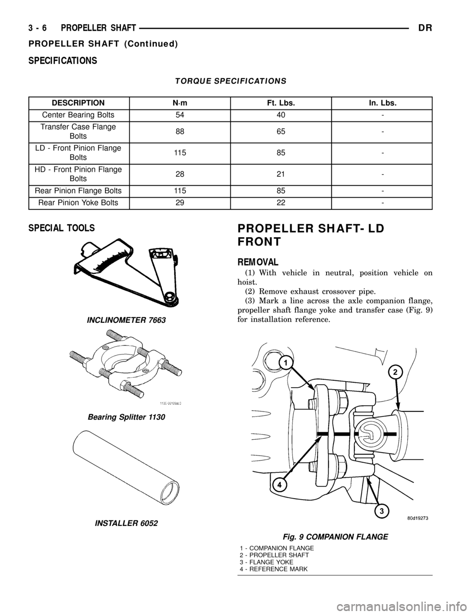
SPECIFICATIONS
TORQUE SPECIFICATIONS
DESCRIPTION N´m Ft. Lbs. In. Lbs.
Center Bearing Bolts 54 40 -
Transfer Case Flange
Bolts88 65 -
LD - Front Pinion Flange
Bolts11 5 8 5 -
HD - Front Pinion Flange
Bolts28 21 -
Rear Pinion Flange Bolts 115 85 -
Rear Pinion Yoke Bolts 29 22 -
SPECIAL TOOLSPROPELLER SHAFT- LD
FRONT
REMOVAL
(1) With vehicle in neutral, position vehicle on
hoist.
(2) Remove exhaust crossover pipe.
(3) Mark a line across the axle companion flange,
propeller shaft flange yoke and transfer case (Fig. 9)
for installation reference.
INCLINOMETER 7663
Bearing Splitter 1130
INSTALLER 6052
Fig. 9 COMPANION FLANGE
1 - COMPANION FLANGE
2 - PROPELLER SHAFT
3 - FLANGE YOKE
4 - REFERENCE MARK
3 - 6 PROPELLER SHAFTDR
PROPELLER SHAFT (Continued)
Page 88 of 2627
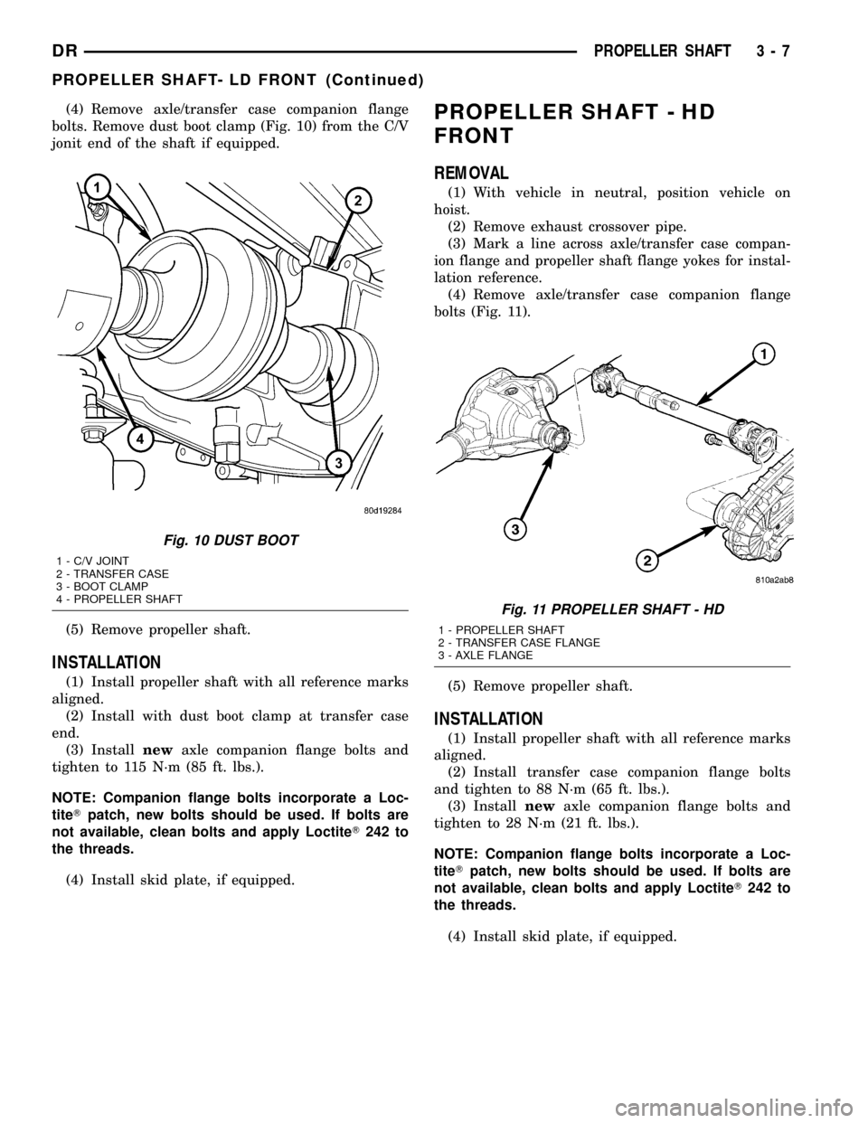
(4) Remove axle/transfer case companion flange
bolts. Remove dust boot clamp (Fig. 10) from the C/V
jonit end of the shaft if equipped.
(5) Remove propeller shaft.
INSTALLATION
(1) Install propeller shaft with all reference marks
aligned.
(2) Install with dust boot clamp at transfer case
end.
(3) Installnewaxle companion flange bolts and
tighten to 115 N´m (85 ft. lbs.).
NOTE: Companion flange bolts incorporate a Loc-
titeTpatch, new bolts should be used. If bolts are
not available, clean bolts and apply LoctiteT242 to
the threads.
(4) Install skid plate, if equipped.
PROPELLER SHAFT - HD
FRONT
REMOVAL
(1) With vehicle in neutral, position vehicle on
hoist.
(2) Remove exhaust crossover pipe.
(3) Mark a line across axle/transfer case compan-
ion flange and propeller shaft flange yokes for instal-
lation reference.
(4) Remove axle/transfer case companion flange
bolts (Fig. 11).
(5) Remove propeller shaft.
INSTALLATION
(1) Install propeller shaft with all reference marks
aligned.
(2) Install transfer case companion flange bolts
and tighten to 88 N´m (65 ft. lbs.).
(3) Installnewaxle companion flange bolts and
tighten to 28 N´m (21 ft. lbs.).
NOTE: Companion flange bolts incorporate a Loc-
titeTpatch, new bolts should be used. If bolts are
not available, clean bolts and apply LoctiteT242 to
the threads.
(4) Install skid plate, if equipped.
Fig. 10 DUST BOOT
1 - C/V JOINT
2 - TRANSFER CASE
3 - BOOT CLAMP
4 - PROPELLER SHAFT
Fig. 11 PROPELLER SHAFT - HD
1 - PROPELLER SHAFT
2 - TRANSFER CASE FLANGE
3 - AXLE FLANGE
DRPROPELLER SHAFT 3 - 7
PROPELLER SHAFT- LD FRONT (Continued)
Page 89 of 2627
REAR PROPELLER SHAFT
REMOVAL
(1) With vehicle in neutral, position vehicle on
hoist.
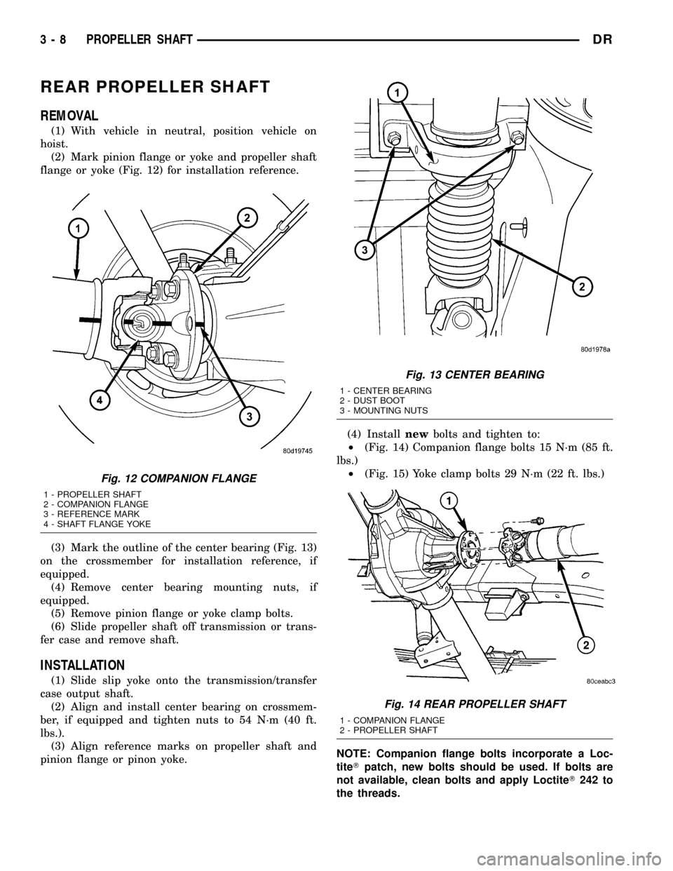
(2) Mark pinion flange or yoke and propeller shaft
flange or yoke (Fig. 12) for installation reference.
(3) Mark the outline of the center bearing (Fig. 13)
on the crossmember for installation reference, if
equipped.
(4) Remove center bearing mounting nuts, if
equipped.
(5) Remove pinion flange or yoke clamp bolts.
(6) Slide propeller shaft off transmission or trans-
fer case and remove shaft.
INSTALLATION
(1) Slide slip yoke onto the transmission/transfer
case output shaft.
(2) Align and install center bearing on crossmem-
ber, if equipped and tighten nuts to 54 N´m (40 ft.
lbs.).
(3) Align reference marks on propeller shaft and
pinion flange or pinon yoke.(4) Installnewbolts and tighten to:
²(Fig. 14) Companion flange bolts 15 N´m (85 ft.
lbs.)
²(Fig. 15) Yoke clamp bolts 29 N´m (22 ft. lbs.)
NOTE: Companion flange bolts incorporate a Loc-
titeTpatch, new bolts should be used. If bolts are
not available, clean bolts and apply LoctiteT242 to
the threads.
Fig. 12 COMPANION FLANGE
1 - PROPELLER SHAFT
2 - COMPANION FLANGE
3 - REFERENCE MARK
4 - SHAFT FLANGE YOKE
Fig. 13 CENTER BEARING
1 - CENTER BEARING
2 - DUST BOOT
3 - MOUNTING NUTS
Fig. 14 REAR PROPELLER SHAFT
1 - COMPANION FLANGE
2 - PROPELLER SHAFT
3 - 8 PROPELLER SHAFTDR
Page 90 of 2627
CENTER BEARING
REMOVAL
(1) Remove rear propeller shaft.
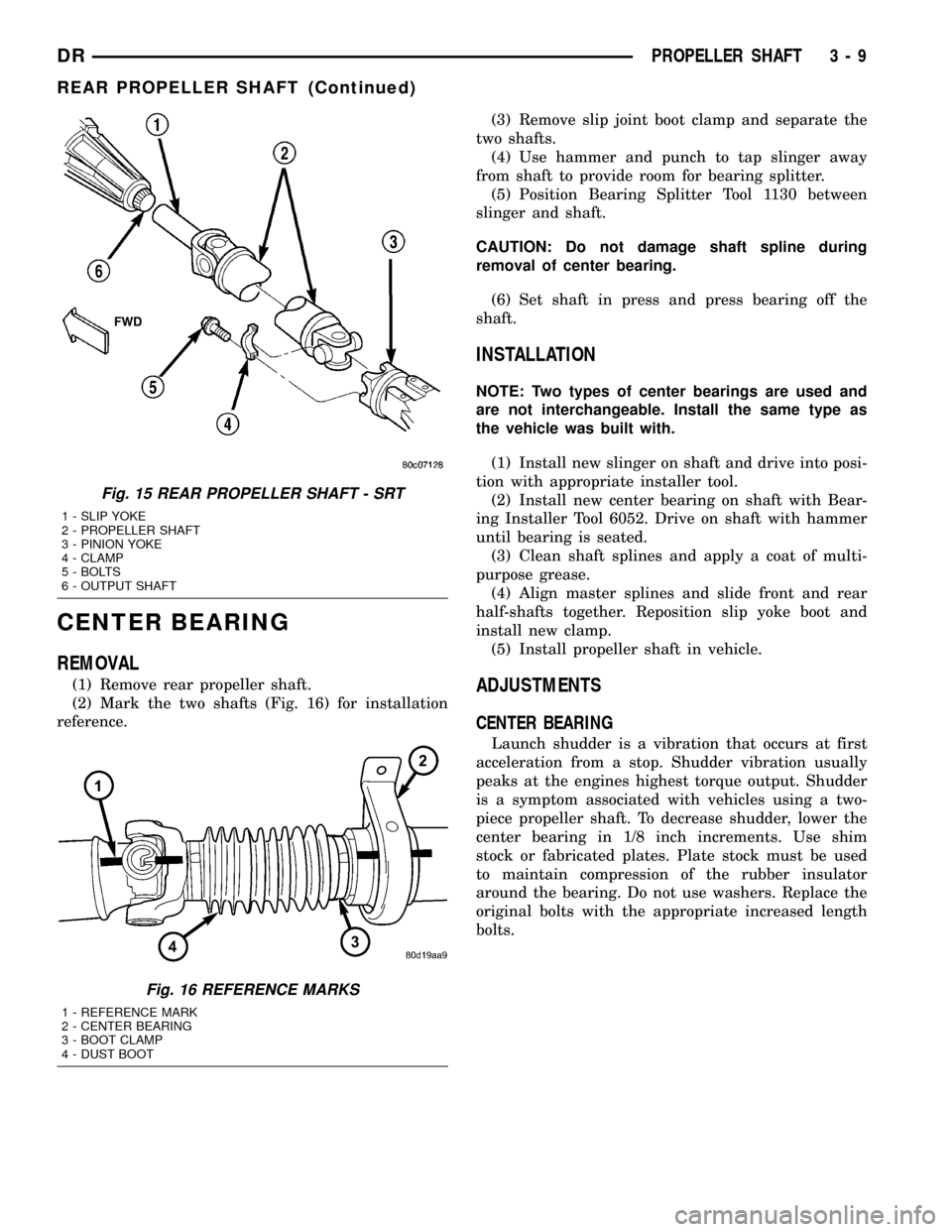
(2) Mark the two shafts (Fig. 16) for installation
reference.(3) Remove slip joint boot clamp and separate the
two shafts.
(4) Use hammer and punch to tap slinger away
from shaft to provide room for bearing splitter.
(5) Position Bearing Splitter Tool 1130 between
slinger and shaft.
CAUTION: Do not damage shaft spline during
removal of center bearing.
(6) Set shaft in press and press bearing off the
shaft.
INSTALLATION
NOTE: Two types of center bearings are used and
are not interchangeable. Install the same type as
the vehicle was built with.
(1) Install new slinger on shaft and drive into posi-
tion with appropriate installer tool.
(2) Install new center bearing on shaft with Bear-
ing Installer Tool 6052. Drive on shaft with hammer
until bearing is seated.
(3) Clean shaft splines and apply a coat of multi-
purpose grease.
(4) Align master splines and slide front and rear
half-shafts together. Reposition slip yoke boot and
install new clamp.
(5) Install propeller shaft in vehicle.
ADJUSTMENTS
CENTER BEARING
Launch shudder is a vibration that occurs at first
acceleration from a stop. Shudder vibration usually
peaks at the engines highest torque output. Shudder
is a symptom associated with vehicles using a two-
piece propeller shaft. To decrease shudder, lower the
center bearing in 1/8 inch increments. Use shim
stock or fabricated plates. Plate stock must be used
to maintain compression of the rubber insulator
around the bearing. Do not use washers. Replace the
original bolts with the appropriate increased length
bolts.
Fig. 15 REAR PROPELLER SHAFT - SRT
1 - SLIP YOKE
2 - PROPELLER SHAFT
3 - PINION YOKE
4 - CLAMP
5 - BOLTS
6 - OUTPUT SHAFT
Fig. 16 REFERENCE MARKS
1 - REFERENCE MARK
2 - CENTER BEARING
3 - BOOT CLAMP
4 - DUST BOOT
DRPROPELLER SHAFT 3 - 9
REAR PROPELLER SHAFT (Continued)
Page 91 of 2627
SINGLE CARDAN UNIVERSAL
JOINTS
DISASSEMBLY
DISASSEMBLY - WITH SNAP RINGS
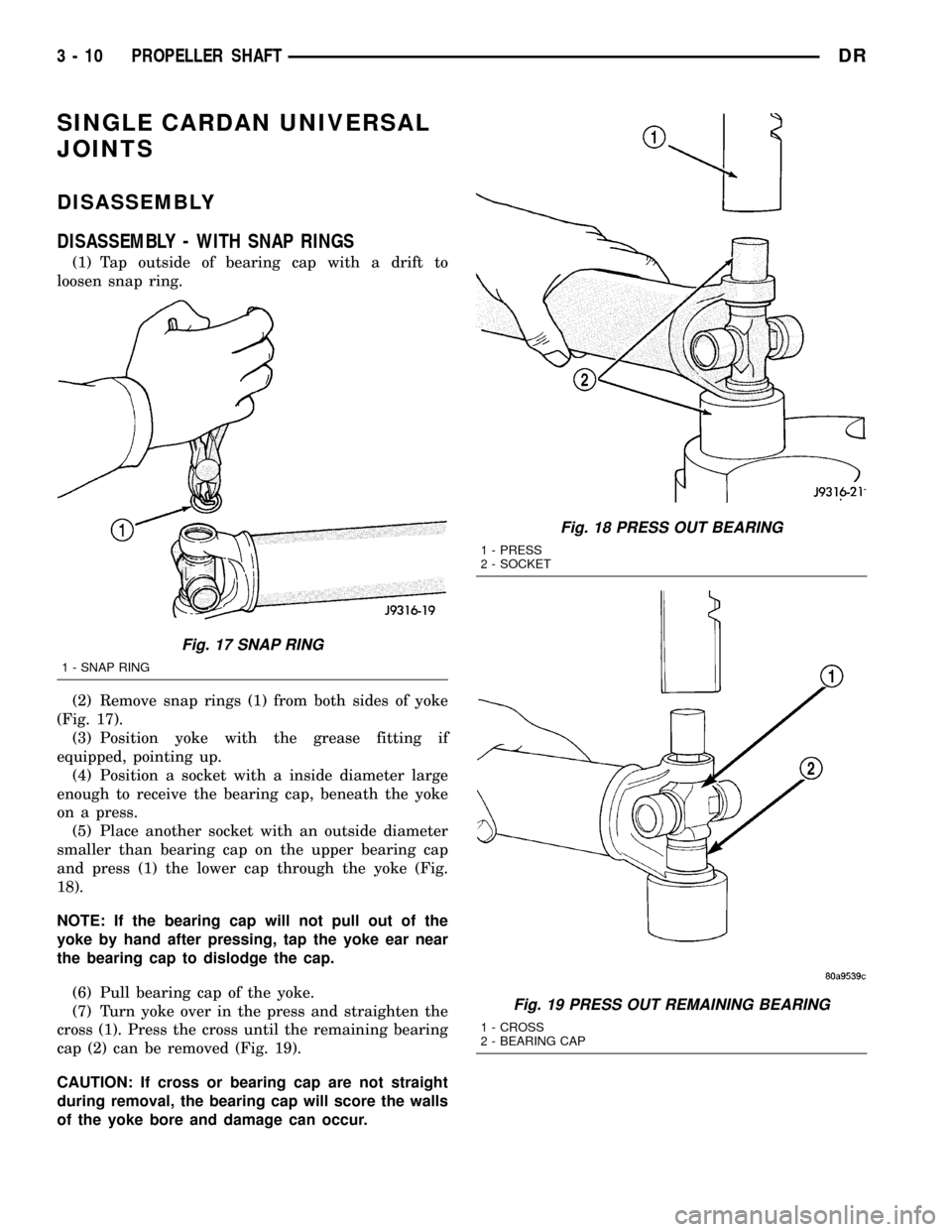
(1) Tap outside of bearing cap with a drift to
loosen snap ring.
(2) Remove snap rings (1) from both sides of yoke
(Fig. 17).
(3) Position yoke with the grease fitting if
equipped, pointing up.
(4) Position a socket with a inside diameter large
enough to receive the bearing cap, beneath the yoke
on a press.
(5) Place another socket with an outside diameter
smaller than bearing cap on the upper bearing cap
and press (1) the lower cap through the yoke (Fig.
18).
NOTE: If the bearing cap will not pull out of the
yoke by hand after pressing, tap the yoke ear near
the bearing cap to dislodge the cap.
(6) Pull bearing cap of the yoke.
(7) Turn yoke over in the press and straighten the
cross (1). Press the cross until the remaining bearing
cap (2) can be removed (Fig. 19).
CAUTION: If cross or bearing cap are not straight
during removal, the bearing cap will score the walls
of the yoke bore and damage can occur.
Fig. 17 SNAP RING
1 - SNAP RING
Fig. 18 PRESS OUT BEARING
1 - PRESS
2 - SOCKET
Fig. 19 PRESS OUT REMAINING BEARING
1 - CROSS
2 - BEARING CAP
3 - 10 PROPELLER SHAFTDR
Page 101 of 2627
HALF SHAFT
TABLE OF CONTENTS
page page
HALF SHAFT
CAUTION.............................20
DIAGNOSIS AND TESTING................20
REMOVAL.............................20
INSTALLATION.........................21
SPECIFICATIONS.......................21
SPECIAL TOOLS.......................21CV JOINT-OUTER
REMOVAL.............................22
INSTALLATION.........................23
CV JOINT-INNER
REMOVAL.............................25
INSTALLATION.........................25
HALF SHAFT
CAUTION
CAUTION:: Never grasp half shaft assembly by the
boots. This may cause the boot to pucker or crease
and reduce the service life of the boot.
Avoid over angulating or stroking the C/V joints
when handling the half shaft.
Half shafts exposed to battery acid, transmission
fluid, brake fluid, differential fluid or gasoline may
cause the boots to deteriorate. Failure to heed cau-
tion may result in damage.
DIAGNOSIS AND TESTING
Check inboard and outboard C/V joint for leaking
grease. This is a sign of boot or boot clamp damage.
NOISE/VIBRATION IN TURNS
A clicking noise or vibration in turns could be
caused by a damaged outer C/V or inner tripod joint
seal boot or seal boot clamps. This will result in the
loss/contamination of the joint grease, resulting in
inadequate lubrication of the joint. Noise could also
be caused by another component of the vehicle com-
ing in contact with the half shafts.
CLUNKING NOISE DURING ACCELERATION
This noise may be a damaged or worn C/V joint. A
torn boot or loose/missing clamp on the inner/outer
joint which has allowed the grease to be lost will
damage the C/V joint.
SHUDDER/VIBRATION DURING ACCELERATION
This could be a worn/damaged inner tripod joint or
a sticking tripod joint. Improper wheel alignment
may also cause a shudder or vibration.
VIBRATION AT HIGHWAY SPEEDS
This problem could be a result of out of balance
front tires or tire/wheel runout. Foreign material
(mud, etc.) packed on the backside of the wheel(s)
will also cause a vibration.
REMOVAL
(1) With vehicle in neutral, position vehicle on
hoist.
(2) Remove half shaft hub nut.
(3) Remove brake caliper and rotor.
(4) Position hydraulic jack under lower suspension
arm and raise jack to unload rebound bumper.
(5) Remove lower shock absorber bolt.
(6) Remove upper ball joint nut and seperate ball
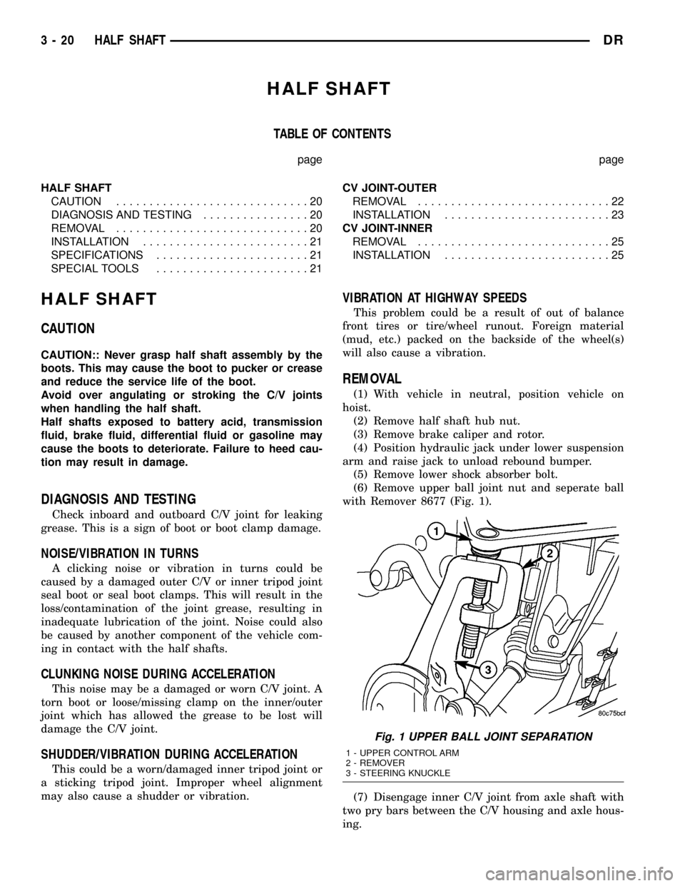
with Remover 8677 (Fig. 1).
(7) Disengage inner C/V joint from axle shaft with
two pry bars between the C/V housing and axle hous-
ing.
Fig. 1 UPPER BALL JOINT SEPARATION
1 - UPPER CONTROL ARM
2 - REMOVER
3 - STEERING KNUCKLE
3 - 20 HALF SHAFTDR
Page 103 of 2627
CV JOINT-OUTER
REMOVAL
(1) Clamp shaft in a vise (with soft jaws) and sup-
port C/V joint.
CAUTION: Do not damage C/V housing or half
shaft.
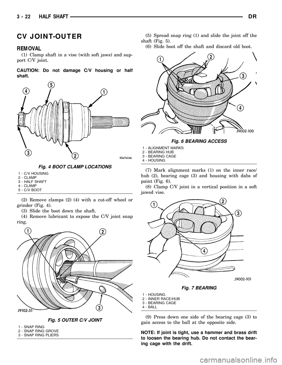
(2) Remove clamps (2) (4) with a cut-off wheel or
grinder (Fig. 4).
(3) Slide the boot down the shaft.
(4) Remove lubricant to expose the C/V joint snap
ring.(5) Spread snap ring (1) and slide the joint off the
shaft (Fig. 5).
(6) Slide boot off the shaft and discard old boot.
(7) Mark alignment marks (1) on the inner race/
hub (2), bearing cage (3) and housing with dabs of
paint (Fig. 6).
(8) Clamp C/V joint in a vertical position in a soft
jawed vise.
(9) Press down one side of the bearing cage (3) to
gain access to the ball at the opposite side.
NOTE: If joint is tight, use a hammer and brass drift
to loosen the bearing hub. Do not contact the bear-
ing cage with the drift.
Fig. 4 BOOT CLAMP LOCATIONS
1 - C/V HOUSING
2 - CLAMP
3 - HALF SHAFT
4 - CLAMP
5 - C/V BOOT
Fig. 5 OUTER C/V JOINT
1 - SNAP RING
2 - SNAP RING GROVE
3 - SNAP RING PLIERS
Fig. 6 BEARING ACCESS
1 - ALIGNMENT MARKS
2 - BEARING HUB
3 - BEARING CAGE
4 - HOUSING
Fig. 7 BEARING
1 - HOUSING
2 - INNER RACE/HUB
3 - BEARING CAGE
4 - BALL
3 - 22 HALF SHAFTDR
Page 106 of 2627
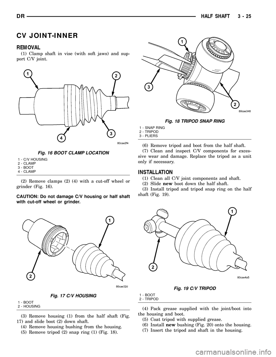
CV JOINT-INNER
REMOVAL
(1) Clamp shaft in vise (with soft jaws) and sup-
port C/V joint.
(2) Remove clamps (2) (4) with a cut-off wheel or
grinder (Fig. 16).
CAUTION: Do not damage C/V housing or half shaft
with cut-off wheel or grinder.
(3) Remove housing (1) from the half shaft (Fig.
17) and slide boot (2) down shaft.
(4) Remove housing bushing from the housing.
(5) Remove tripod (2) snap ring (1) (Fig. 18).(6) Remove tripod and boot from the half shaft.
(7) Clean and inspect C/V components for exces-
sive wear and damage. Replace the tripod as a unit
only if necessary.
INSTALLATION
(1) Clean all C/V joint components and shaft.
(2) Slidenewboot down the half shaft.
(3) Install tripod and tripod snap ring on the half
shaft (Fig. 19).
(4) Pack grease supplied with the joint/boot into
the housing and boot.
(5) Coat tripod with supplied grease.
(6) Installnewbushing (Fig. 20) onto the housing.
(7) Insert the tripod and shaft in the housing.
Fig. 16 BOOT CLAMP LOCATION
1 - C/V HOUSING
2 - CLAMP
3 - BOOT
4 - CLAMP
Fig. 17 C/V HOUSING
1 - BOOT
2 - HOUSING
Fig. 18 TRIPOD SNAP RING
1 - SNAP RING
2 - TRIPOD
3 - PLIERS
Fig. 19 C/V TRIPOD
1 - BOOT
2 - TRIPOD
DRHALF SHAFT 3 - 25
Page 108 of 2627

FRONT AXLE - C205F
TABLE OF CONTENTS
page page
FRONT AXLE - C205F
DIAGNOSIS AND TESTING................27
REMOVAL.............................31
INSTALLATION.........................31
ADJUSTMENTS........................32
SPECIFICATIONS.......................39
SPECIAL TOOLS.......................40
AXLE SHAFTS
REMOVAL.............................43
INSTALLATION.........................43
AXLE SHAFT SEALS
REMOVAL.............................43
INSTALLATION.........................43
AXLE BEARINGS
REMOVAL.............................43INSTALLATION.........................44
PINION SEAL
REMOVAL.............................44
INSTALLATION.........................45
DIFFERENTIAL
REMOVAL.............................46
DISASSEMBLY.........................47
ASSEMBLY............................47
INSTALLATION.........................48
DIFFERENTIAL CASE BEARINGS
REMOVAL.............................48
INSTALLATION.........................48
PINION GEAR/RING GEAR
REMOVAL.............................49
INSTALLATION.........................51
FRONT AXLE - C205F
DIAGNOSIS AND TESTING
GEAR NOISE
Axle gear noise can be caused by insufficient lubri-
cant, incorrect backlash, tooth contact, worn/damaged
gears or the carrier housing not having the proper
offset and squareness.
Gear noise usually happens at a specific speed
range. The noise can also occur during a specific type
of driving condition. These conditions are accelera-
tion, deceleration, coast, or constant load.
When road testing, first warm-up the axle fluid by
driving the vehicle at least 5 miles and then acceler-
ate the vehicle to the speed range where the noise is
the greatest. Shift out-of-gear and coast through the
peak-noise range. If the noise stops or changes
greatly check for:
²Insufficient lubricant.
²Incorrect ring gear backlash.
²Gear damage.
Differential side gears and pinions can be checked
by turning the vehicle. The side gears are loaded dur-
ing turns. They usually do not cause noise during
straight-ahead driving when the gears are unloaded.
A worn pinion mate shaft can also cause a snapping
or a knocking noise.
BEARING NOISE
The axle shaft, differential and pinion bearings can
all produce noise when worn or damaged. Bearing
noise can be either a whining, or a growling sound.
Pinion bearingshave a constant-pitch noise. This
noise changes only with vehicle speed. Pinion bearing
noise will be higher pitched because it rotates at a
faster rate. Drive the vehicle and load the differen-
tial. If bearing noise occurs, the rear pinion bearing
is the source of the noise. If the bearing noise is
heard during a coast, the front pinion bearing is the
source.
Differential bearingsusually produce a low pitch
noise. Differential bearing noise is similar to pinion
bearing noise. The pitch of differential bearing noise
is also constant and varies only with vehicle speed.
Axle shaft bearingsproduce noise and vibration
when worn or damaged. The noise generally changes
when the bearings are loaded. Road test the vehicle.
Turn the vehicle sharply to the left and to the right.
This will load the bearings and change the noise
level. Where axle bearing damage is slight, the noise
is usually not noticeable at speeds above 30 m.p.h.
LOW SPEED KNOCK
Low speed knock is generally caused by:
²Worn U-joints/CV joint.
²Worn side-gear thrust washers.
²Worn pinion shaft bore.
DRFRONT AXLE - C205F 3 - 27