Removal DODGE RAM 1500 1998 2.G Repair Manual
[x] Cancel search | Manufacturer: DODGE, Model Year: 1998, Model line: RAM 1500, Model: DODGE RAM 1500 1998 2.GPages: 2627
Page 176 of 2627
(3) Install the axle shaft.
(4) Install differential cover and fill with gear
lubricant to the bottom of the fill plug hole.
AXLE BEARINGS
REMOVAL
(1) Remove axle shaft.
(2) Remove axle shaft seal from axle tube with a
small pry bar.
NOTE: The seal and bearing can be removed at the
same time with the bearing removal tool.
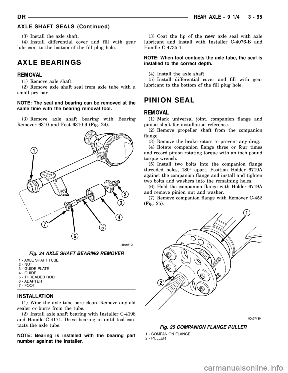
(3) Remove axle shaft bearing with Bearing
Remover 6310 and Foot 6310-9 (Fig. 24).
INSTALLATION
(1) Wipe the axle tube bore clean. Remove any old
sealer or burrs from the tube.
(2) Install axle shaft bearing with Installer C-4198
and Handle C-4171. Drive bearing in until tool con-
tacts the axle tube.
NOTE: Bearing is installed with the bearing part
number against the installer.(3) Coat the lip of thenewaxle seal with axle
lubricant and install with Installer C-4076-B and
Handle C-4735-1.
NOTE: When tool contacts the axle tube, the seal is
installed to the correct depth.
(4) Install the axle shaft.
(5) Install differential cover and fill with gear
lubricant to the bottom of the fill plug hole.
PINION SEAL
REMOVAL
(1) Mark universal joint, companion flange and
pinion shaft for installation reference.
(2) Remove propeller shaft from the companion
flange.
(3) Remove the brake rotors to prevent any drag.
(4) Rotate companion flange three or four times
and record pinion rotating torque with an inch pound
torque wrench.
(5) Install two bolts into the companion flange
threaded holes, 180É apart. Position Holder 6719A
against the companion flange and install and tighten
two bolts and washers into the remaining holes.
(6) Hold the companion flange with Holder 6719A
and remove pinion nut and washer.
(7) Remove companion flange with Remover C-452
(Fig. 25).
Fig. 24 AXLE SHAFT BEARING REMOVER
1 - AXLE SHAFT TUBE
2 - NUT
3 - GUIDE PLATE
4 - GUIDE
5 - THREADED ROD
6 - ADAPTER
7 - FOOT
Fig. 25 COMPANION FLANGE PULLER
1 - COMPANION FLANGE
2 - PULLER
DRREAR AXLE - 9 1/4 3 - 95
AXLE SHAFT SEALS (Continued)
Page 177 of 2627
(8) Remove pinion seal with pry tool or slide-ham-
mer mounted screw.
INSTALLATION
(1) Apply a light coating of gear lubricant on the
lip of pinion seal.
(2) Installnewpinion seal with Installer C-3860-A
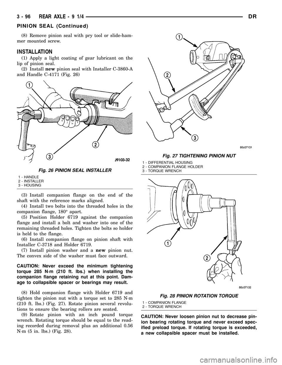
and Handle C-4171 (Fig. 26)
(3) Install companion flange on the end of the
shaft with the reference marks aligned.
(4) Install two bolts into the threaded holes in the
companion flange, 180É apart.
(5) Position Holder 6719 against the companion
flange and install a bolt and washer into one of the
remaining threaded holes. Tighten the bolts so holder
is held to the flange.
(6) Install companion flange on pinion shaft with
Installer C-3718 and Holder 6719.
(7) Install pinion washer and anewpinion nut.
The convex side of the washer must face outward.
CAUTION: Never exceed the minimum tightening
torque 285 N´m (210 ft. lbs.) when installing the
companion flange retaining nut at this point. Dam-
age to collapsible spacer or bearings may result.
(8) Hold companion flange with Holder 6719 and
tighten the pinion nut with a torque set to 285 N´m
(210 ft. lbs.) (Fig. 27). Rotate pinion several revolu-
tions to ensure the bearing rollers are seated.
(9) Rotate pinion with an inch pound torque
wrench. Rotating torque should be equal to the read-
ing recorded during removal plus an additional 0.56
N´m (5 in. lbs.) (Fig. 28).CAUTION: Never loosen pinion nut to decrease pin-
ion bearing rotating torque and never exceed spec-
ified preload torque. If rotating torque is exceeded,
a new collapsible spacer must be installed.
Fig. 26 PINION SEAL INSTALLER
1 - HANDLE
2 - INSTALLER
3 - HOUSING
Fig. 27 TIGHTENING PINION NUT
1 - DIFFERENTIAL HOUSING
2 - COMPANION FLANGE HOLDER
3 - TORQUE WRENCH
Fig. 28 PINION ROTATION TORQUE
1 - COMPANION FLANGE
2 - TORQUE WRENCH
3 - 96 REAR AXLE-91/4DR
PINION SEAL (Continued)
Page 178 of 2627
(10) If rotating torque is low, use Holder 6719 to
hold the companion flange and tighten pinion nut in
6.8 N´m (5 ft. lbs.) increments until proper rotating
torque is achieved.
NOTE: The bearing rotating torque should be con-
stant during a complete revolution of the pinion. If
the rotating torque varies, this indicates a binding
condition.
NOTE: The seal replacement is unacceptable if the
final pinion nut torque is less than 285 N´m (210 ft.
lbs.).
(11) Install propeller shaft with the installation
reference marks aligned.
(12) Tighten the companion flange bolts to 108
N´m (80 ft. lbs.).
(13) Install brake rotors.
(14) Check the differential lubricant level.
DIFFERENTIAL COVER
REMOVAL
(1) With vehicle in neutral, position vehicle on
hoist.
(2) Remove drain plug.
(3) Remove cover bolts.
(4) Remove cover and drain lubricant.
INSTALLATION
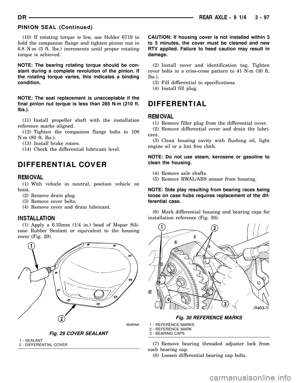
(1) Apply a 6.35mm (1/4 in.) bead of Mopar Sili-
cone Rubber Sealant or equivalent to the housing
cover (Fig. 29).CAUTION: If housing cover is not installed within 3
to 5 minutes, the cover must be cleaned and new
RTV applied. Failure to heed caution may result in
damage.
(2) Install cover and identification tag. Tighten
cover bolts in a criss-cross pattern to 41 N´m (30 ft.
lbs.).
(3) Fill differential to specifications.
(4) Install fill plug.
DIFFERENTIAL
REMOVAL
(1) Remove filler plug from the differential cover.
(2) Remove differential cover and drain the lubri-
cant.
(3) Clean housing cavity with flushing oil, light
engine oil or a lint free cloth.
NOTE: Do not use steam, kerosene or gasoline to
clean the housing.
(4) Remove axle shafts.
(5) Remove RWAL/ABS sensor from housing.
NOTE: Side play resulting from bearing races being
loose on case hubs requires replacement of the dif-
ferential case.
(6) Mark differential housing and bearing caps for
installation reference (Fig. 30).
(7) Remove bearing threaded adjuster lock from
each bearing cap.
(8) Loosen differential bearing cap bolts.
Fig. 29 COVER SEALANT
1 - SEALANT
2 - DIFFERENTIAL COVER
Fig. 30 REFERENCE MARKS
1 - REFERENCE MARKS
2 - REFERENCE MARK
3 - BEARING CAPS
DRREAR AXLE - 9 1/4 3 - 97
PINION SEAL (Continued)
Page 184 of 2627
(10) Loosen forcing screw in small increments
until the clutch pack tension is relieved and differen-
tial case can be turned using turning bar.
(11) Rotate differential case until the pinion gears
can be removed.
(12) Remove pinion gears from differential case.(13) Remove forcing screw and discs.
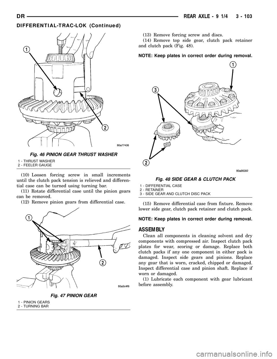
(14) Remove top side gear, clutch pack retainer
and clutch pack (Fig. 48).
NOTE: Keep plates in correct order during removal.
(15) Remove differential case from fixture. Remove
lower side gear, clutch pack retainer and clutch pack.
NOTE: Keep plates in correct order during removal.
ASSEMBLY
Clean all components in cleaning solvent and dry
components with compressed air. Inspect clutch pack
plates for wear, scoring or damage. Replace both
clutch packs if any one component in either pack is
damaged. Inspect side gears and pinions. Replace
any gear that is worn, cracked, chipped or damaged.
Inspect differential case and pinion shaft. Replace if
worn or damaged.
(1) Lubricate each component with gear lubricant
before assembly.
Fig. 46 PINION GEAR THRUST WASHER
1 - THRUST WASHER
2 - FEELER GAUGE
Fig. 47 PINION GEAR
1 - PINION GEARS
2 - TURNING BAR
Fig. 48 SIDE GEAR & CLUTCH PACK
1 - DIFFERENTIAL CASE
2 - RETAINER
3 - SIDE GEAR AND CLUTCH DISC PACK
DRREAR AXLE - 9 1/4 3 - 103
DIFFERENTIAL-TRAC-LOK (Continued)
Page 186 of 2627
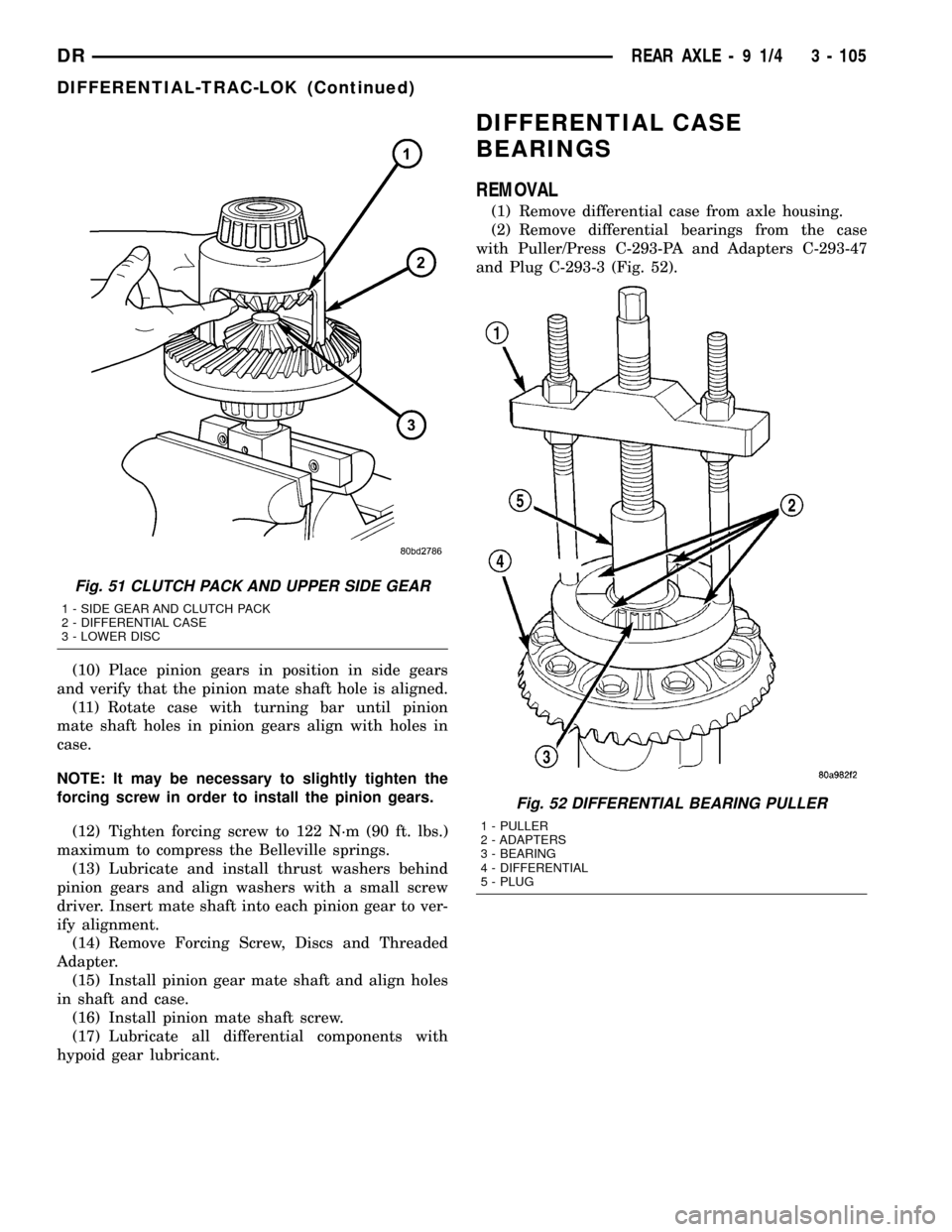
(10) Place pinion gears in position in side gears
and verify that the pinion mate shaft hole is aligned.
(11) Rotate case with turning bar until pinion
mate shaft holes in pinion gears align with holes in
case.
NOTE: It may be necessary to slightly tighten the
forcing screw in order to install the pinion gears.
(12) Tighten forcing screw to 122 N´m (90 ft. lbs.)
maximum to compress the Belleville springs.
(13) Lubricate and install thrust washers behind
pinion gears and align washers with a small screw
driver. Insert mate shaft into each pinion gear to ver-
ify alignment.
(14) Remove Forcing Screw, Discs and Threaded
Adapter.
(15) Install pinion gear mate shaft and align holes
in shaft and case.
(16) Install pinion mate shaft screw.
(17) Lubricate all differential components with
hypoid gear lubricant.
DIFFERENTIAL CASE
BEARINGS
REMOVAL
(1) Remove differential case from axle housing.
(2) Remove differential bearings from the case
with Puller/Press C-293-PA and Adapters C-293-47
and Plug C-293-3 (Fig. 52).
Fig. 51 CLUTCH PACK AND UPPER SIDE GEAR
1 - SIDE GEAR AND CLUTCH PACK
2 - DIFFERENTIAL CASE
3 - LOWER DISC
Fig. 52 DIFFERENTIAL BEARING PULLER
1 - PULLER
2 - ADAPTERS
3 - BEARING
4 - DIFFERENTIAL
5 - PLUG
DRREAR AXLE - 9 1/4 3 - 105
DIFFERENTIAL-TRAC-LOK (Continued)
Page 187 of 2627
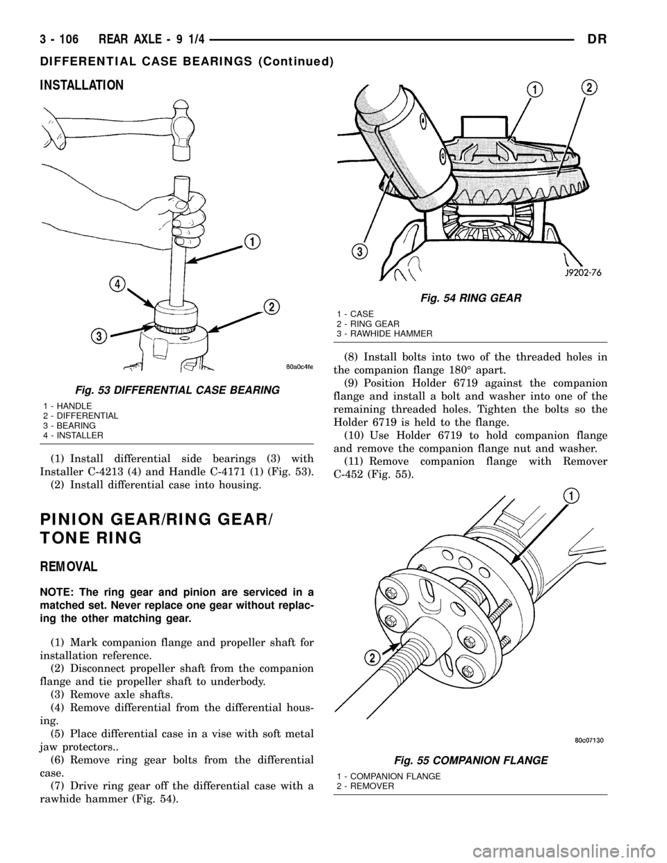
INSTALLATION
(1) Install differential side bearings (3) with
Installer C-4213 (4) and Handle C-4171 (1) (Fig. 53).
(2) Install differential case into housing.
PINION GEAR/RING GEAR/
TONE RING
REMOVAL
NOTE: The ring gear and pinion are serviced in a
matched set. Never replace one gear without replac-
ing the other matching gear.
(1) Mark companion flange and propeller shaft for
installation reference.
(2) Disconnect propeller shaft from the companion
flange and tie propeller shaft to underbody.
(3) Remove axle shafts.
(4) Remove differential from the differential hous-
ing.
(5) Place differential case in a vise with soft metal
jaw protectors..
(6) Remove ring gear bolts from the differential
case.
(7) Drive ring gear off the differential case with a
rawhide hammer (Fig. 54).(8) Install bolts into two of the threaded holes in
the companion flange 180É apart.
(9) Position Holder 6719 against the companion
flange and install a bolt and washer into one of the
remaining threaded holes. Tighten the bolts so the
Holder 6719 is held to the flange.
(10) Use Holder 6719 to hold companion flange
and remove the companion flange nut and washer.
(11) Remove companion flange with Remover
C-452 (Fig. 55).
Fig. 53 DIFFERENTIAL CASE BEARING
1 - HANDLE
2 - DIFFERENTIAL
3 - BEARING
4 - INSTALLER
Fig. 54 RING GEAR
1 - CASE
2 - RING GEAR
3 - RAWHIDE HAMMER
Fig. 55 COMPANION FLANGE
1 - COMPANION FLANGE
2 - REMOVER
3 - 106 REAR AXLE-91/4DR
DIFFERENTIAL CASE BEARINGS (Continued)
Page 193 of 2627
REAR AXLE - 10 1/2 AA
TABLE OF CONTENTS
page page
REAR AXLE - 10 1/2 AA
DIAGNOSIS AND TESTING...............112
REMOVAL............................115
INSTALLATION........................116
ADJUSTMENTS.......................116
SPECIFICATIONS......................120
SPECIAL TOOLS.......................120
AXLE SHAFTS
REMOVAL............................124
INSTALLATION........................124
AXLE BEARINGS
REMOVAL............................125
INSTALLATION........................125
PINION SEAL
REMOVAL............................126
INSTALLATION........................126
DIFFERENTIAL
REMOVAL............................127DISASSEMBLY........................128
ASSEMBLY...........................129
INSTALLATION........................130
DIFFERENTIAL TRAC-RITE
DESCRIPTION........................131
OPERATION..........................131
DISASSEMBLY........................131
CLEANING...........................132
INSPECTION.........................132
ASSEMBLY...........................133
DIFFERENTIAL CASE BEARINGS
REMOVAL............................134
INSTALLATION........................134
PINION GEAR/RING GEAR/TONE RING
REMOVAL............................134
INSTALLATION........................137
REAR AXLE - 10 1/2 AA
DIAGNOSIS AND TESTING
GEAR NOISE
Axle gear noise can be caused by insufficient lubri-
cant, incorrect backlash, incorrect pinion depth, tooth
contact, worn/damaged gears, or the carrier housing
not having the proper offset and squareness.
Gear noise usually happens at a specific speed
range. The noise can also occur during a specific type
of driving condition. These conditions are accelera-
tion, deceleration, coast, or constant load.
When road testing, first warm-up the axle fluid by
driving the vehicle at least 5 miles and then acceler-
ate the vehicle to the speed range where the noise is
the greatest. Shift out-of-gear and coast through the
peak-noise range. If the noise stops or changes
greatly check for:
²Insufficient lubricant.
²Incorrect ring gear backlash.
²Gear damage.
Differential side gears and pinions can be checked
by turning the vehicle. The side gears are loaded dur-
ing turns. They usually do not cause noise during
straight-ahead driving when the gears are unloaded.
A worn pinion shaft can also cause a snapping or a
knocking noise.
BEARING NOISE
The axle shaft, differential and pinion bearings can
all produce noise when worn or damaged. Bearing
noise can be either a whining, or a growling sound.
Pinion bearingshave a constant-pitch noise. This
noise changes only with vehicle speed. Pinion bearing
noise will be higher pitched because it rotates at a
faster rate. Drive the vehicle and load the differen-
tial. If bearing noise occurs, the rear pinion bearing
is the source of the noise. If the bearing noise is
heard during a coast, the front pinion bearing is the
source.
Differential bearingsusually produce a low pitch
noise. Differential bearing noise is similar to pinion
bearing noise. The pitch of differential bearing noise
is also constant and varies only with vehicle speed.
Axle shaft bearingsproduce noise and vibration
when worn or damaged. The noise generally changes
when the bearings are loaded. Road test the vehicle.
Turn the vehicle sharply to the left and to the right.
This will load the bearings and change the noise
level. Where axle bearing damage is slight, the noise
is usually not noticeable at speeds above 30 m.p.h.
LOW SPEED KNOCK
Low speed knock is generally caused by:
²Worn U-joint(s).
²Worn side-gear thrust washers.
²Worn pinion shaft bore.
3 - 112 REAR AXLE - 10 1/2 AADR
Page 196 of 2627
Condition Possible Causes Correction
Axle Noise 1. Insufficient lubricant. 1. Fill differential with the correct fluid
type and quantity.
2. Improper ring gear and pinion
adjustment.2. Check ring gear and pinion contact
pattern. Adjust backlash or pinion
depth.
3. Unmatched ring gear and pinion. 3. Replace gears with a matched ring
gear and pinion.
4. Worn teeth on ring gear and/or
pinion.4. Replace ring gear and pinion.
5. Loose pinion bearings. 5. Adjust pinion bearing pre-load.
6. Loose differential bearings. 6. Adjust differential bearing pre-load.
7. Mis-aligned or sprung ring gear. 7. Measure ring gear run-out. Replace
components as necessary.
8. Loose differential bearing cap
bolts.8. Inspect differential components and
replace as necessary. Ensure that the
bearing caps are torqued tot he
proper specification.
9. Housing not machined properly. 9. Replace housing.
REMOVAL
(1) Raise and support the vehicle.
(2) Position a lift under axle and secure lift to the
axle.
(3) Remove wheels and tires assemblies.
(4) Remove all brake components.
(5) Mark propeller shaft and companion flange for
installation alignment reference.
(6) Remove propeller shaft.
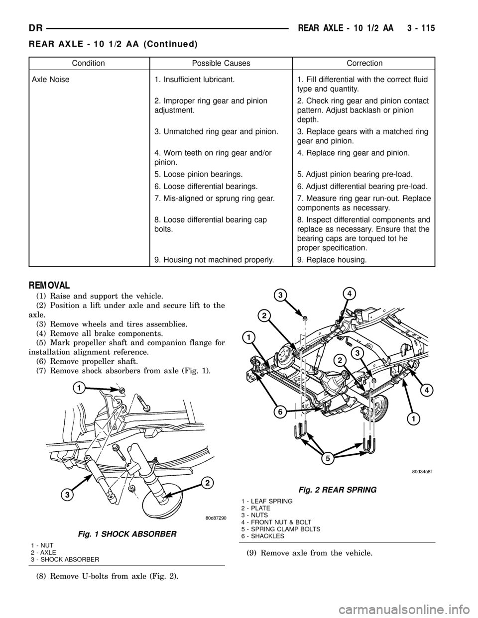
(7) Remove shock absorbers from axle (Fig. 1).
(8) Remove U-bolts from axle (Fig. 2).(9) Remove axle from the vehicle.
Fig. 1 SHOCK ABSORBER
1 - NUT
2 - AXLE
3 - SHOCK ABSORBER
Fig. 2 REAR SPRING
1 - LEAF SPRING
2 - PLATE
3 - NUTS
4 - FRONT NUT & BOLT
5 - SPRING CLAMP BOLTS
6 - SHACKLES
DRREAR AXLE - 10 1/2 AA 3 - 115
REAR AXLE - 10 1/2 AA (Continued)
Page 205 of 2627
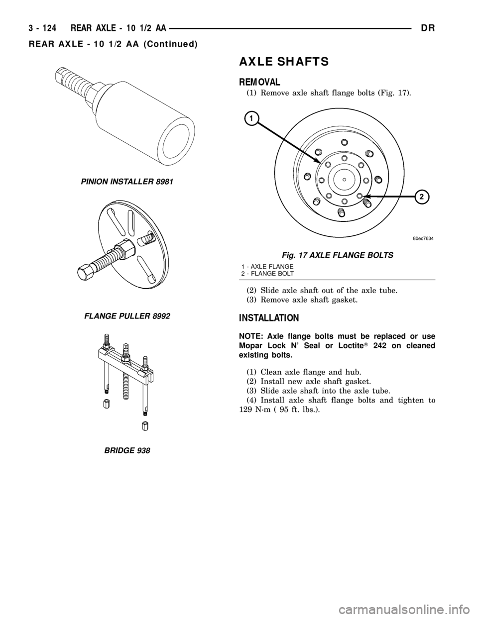
AXLE SHAFTS
REMOVAL
(1) Remove axle shaft flange bolts (Fig. 17).
(2) Slide axle shaft out of the axle tube.
(3) Remove axle shaft gasket.
INSTALLATION
NOTE: Axle flange bolts must be replaced or use
Mopar Lock N' Seal or LoctiteT242 on cleaned
existing bolts.
(1) Clean axle flange and hub.
(2) Install new axle shaft gasket.
(3) Slide axle shaft into the axle tube.
(4) Install axle shaft flange bolts and tighten to
129 N´m ( 95 ft. lbs.).
PINION INSTALLER 8981
FLANGE PULLER 8992
BRIDGE 938
Fig. 17 AXLE FLANGE BOLTS
1 - AXLE FLANGE
2 - FLANGE BOLT
3 - 124 REAR AXLE - 10 1/2 AADR
REAR AXLE - 10 1/2 AA (Continued)
Page 206 of 2627
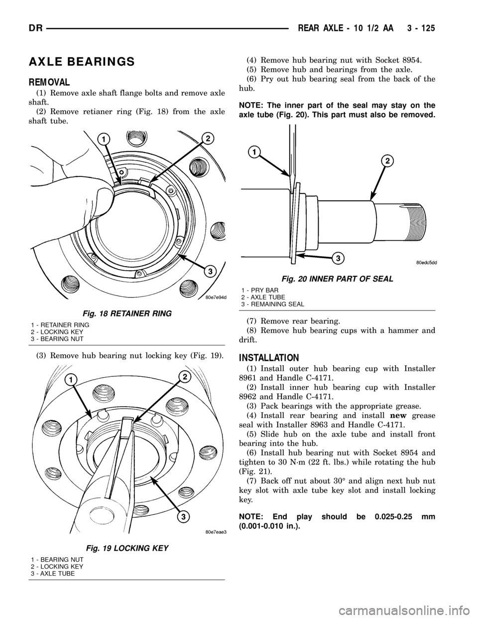
AXLE BEARINGS
REMOVAL
(1) Remove axle shaft flange bolts and remove axle
shaft.
(2) Remove retianer ring (Fig. 18) from the axle
shaft tube.
(3) Remove hub bearing nut locking key (Fig. 19).(4) Remove hub bearing nut with Socket 8954.
(5) Remove hub and bearings from the axle.
(6) Pry out hub bearing seal from the back of the
hub.
NOTE: The inner part of the seal may stay on the
axle tube (Fig. 20). This part must also be removed.
(7) Remove rear bearing.
(8) Remove hub bearing cups with a hammer and
drift.
INSTALLATION
(1) Install outer hub bearing cup with Installer
8961 and Handle C-4171.
(2) Install inner hub bearing cup with Installer
8962 and Handle C-4171.
(3) Pack bearings with the appropriate grease.
(4) Install rear bearing and installnewgrease
seal with Installer 8963 and Handle C-4171.
(5) Slide hub on the axle tube and install front
bearing into the hub.
(6) Install hub bearing nut with Socket 8954 and
tighten to 30 N´m (22 ft. lbs.) while rotating the hub
(Fig. 21).
(7) Back off nut about 30É and align next hub nut
key slot with axle tube key slot and install locking
key.
NOTE: End play should be 0.025-0.25 mm
(0.001-0.010 in.).
Fig. 18 RETAINER RING
1 - RETAINER RING
2 - LOCKING KEY
3 - BEARING NUT
Fig. 19 LOCKING KEY
1 - BEARING NUT
2 - LOCKING KEY
3 - AXLE TUBE
Fig. 20 INNER PART OF SEAL
1-PRYBAR
2 - AXLE TUBE
3 - REMAINING SEAL
DRREAR AXLE - 10 1/2 AA 3 - 125