Removal DODGE RAM 1500 1998 2.G Workshop Manual
[x] Cancel search | Manufacturer: DODGE, Model Year: 1998, Model line: RAM 1500, Model: DODGE RAM 1500 1998 2.GPages: 2627
Page 1531 of 2627
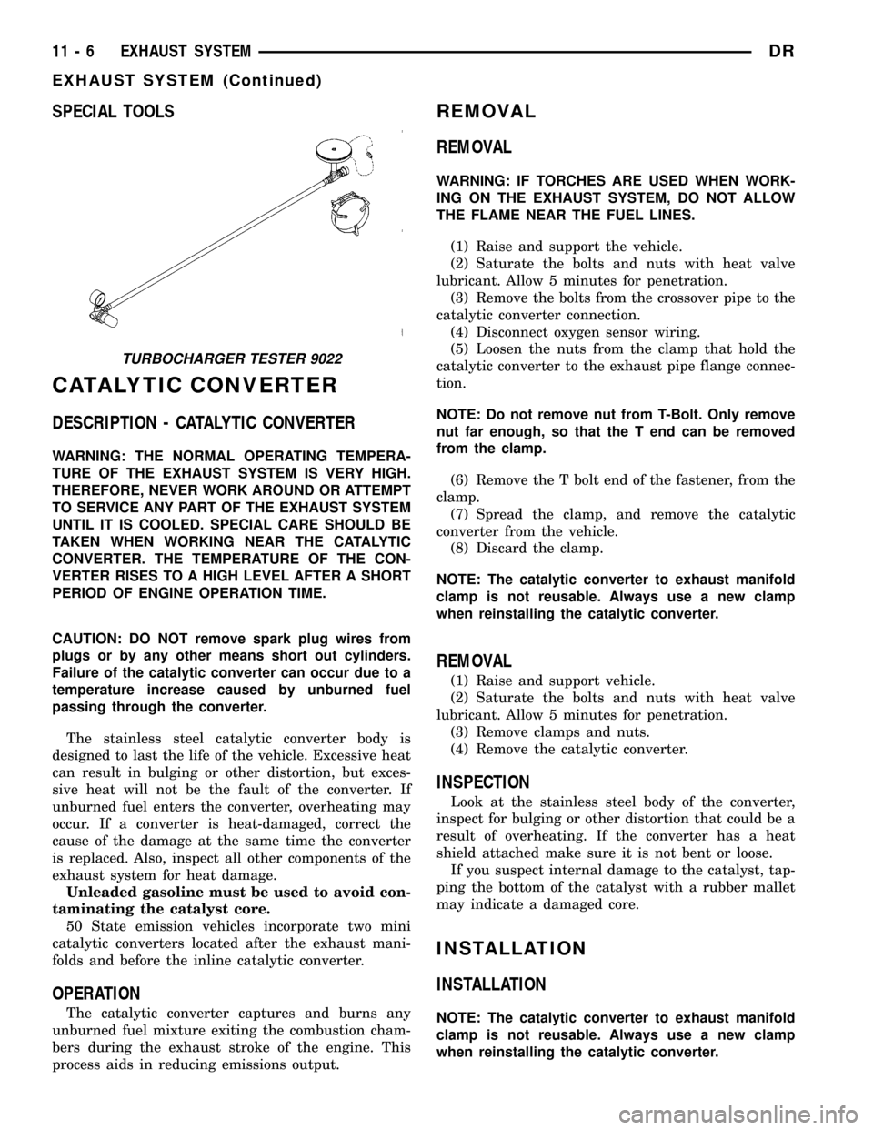
SPECIAL TOOLS
CATALYTIC CONVERTER
DESCRIPTION - CATALYTIC CONVERTER
WARNING: THE NORMAL OPERATING TEMPERA-
TURE OF THE EXHAUST SYSTEM IS VERY HIGH.
THEREFORE, NEVER WORK AROUND OR ATTEMPT
TO SERVICE ANY PART OF THE EXHAUST SYSTEM
UNTIL IT IS COOLED. SPECIAL CARE SHOULD BE
TAKEN WHEN WORKING NEAR THE CATALYTIC
CONVERTER. THE TEMPERATURE OF THE CON-
VERTER RISES TO A HIGH LEVEL AFTER A SHORT
PERIOD OF ENGINE OPERATION TIME.
CAUTION: DO NOT remove spark plug wires from
plugs or by any other means short out cylinders.
Failure of the catalytic converter can occur due to a
temperature increase caused by unburned fuel
passing through the converter.
The stainless steel catalytic converter body is
designed to last the life of the vehicle. Excessive heat
can result in bulging or other distortion, but exces-
sive heat will not be the fault of the converter. If
unburned fuel enters the converter, overheating may
occur. If a converter is heat-damaged, correct the
cause of the damage at the same time the converter
is replaced. Also, inspect all other components of the
exhaust system for heat damage.
Unleaded gasoline must be used to avoid con-
taminating the catalyst core.
50 State emission vehicles incorporate two mini
catalytic converters located after the exhaust mani-
folds and before the inline catalytic converter.
OPERATION
The catalytic converter captures and burns any
unburned fuel mixture exiting the combustion cham-
bers during the exhaust stroke of the engine. This
process aids in reducing emissions output.
REMOVAL
REMOVAL
WARNING: IF TORCHES ARE USED WHEN WORK-
ING ON THE EXHAUST SYSTEM, DO NOT ALLOW
THE FLAME NEAR THE FUEL LINES.
(1) Raise and support the vehicle.
(2) Saturate the bolts and nuts with heat valve
lubricant. Allow 5 minutes for penetration.
(3) Remove the bolts from the crossover pipe to the
catalytic converter connection.
(4) Disconnect oxygen sensor wiring.
(5) Loosen the nuts from the clamp that hold the
catalytic converter to the exhaust pipe flange connec-
tion.
NOTE: Do not remove nut from T-Bolt. Only remove
nut far enough, so that the T end can be removed
from the clamp.
(6) Remove the T bolt end of the fastener, from the
clamp.
(7) Spread the clamp, and remove the catalytic
converter from the vehicle.
(8) Discard the clamp.
NOTE: The catalytic converter to exhaust manifold
clamp is not reusable. Always use a new clamp
when reinstalling the catalytic converter.
REMOVAL
(1) Raise and support vehicle.
(2) Saturate the bolts and nuts with heat valve
lubricant. Allow 5 minutes for penetration.
(3) Remove clamps and nuts.
(4) Remove the catalytic converter.
INSPECTION
Look at the stainless steel body of the converter,
inspect for bulging or other distortion that could be a
result of overheating. If the converter has a heat
shield attached make sure it is not bent or loose.
If you suspect internal damage to the catalyst, tap-
ping the bottom of the catalyst with a rubber mallet
may indicate a damaged core.
INSTALLATION
INSTALLATION
NOTE: The catalytic converter to exhaust manifold
clamp is not reusable. Always use a new clamp
when reinstalling the catalytic converter.
TURBOCHARGER TESTER 9022
11 - 6 EXHAUST SYSTEMDR
EXHAUST SYSTEM (Continued)
Page 1532 of 2627
(1) Position the catalytic converter onto the
exhaust pipe flange connection. Tighten the nuts to
28 N´m (250 in. lbs.) torque.
(2) Install the muffler onto the catalytic converter
until the alignment tab is inserted into the align-
ment slot.
(3) Install the exhaust clamp at the muffler and
catalytic converter connection. Tighten the clamp
nuts to 54.2 N´m (40 ft. lbs.) torque.
(4) Connect oxygen sensor wiring.
(5) Lower the vehicle.
(6) Start the engine and inspect for exhaust leaks.
Reair exhaust leaks as necessary.
(7) Check the exhaust system for contact with the
body panels. A minimum of 25.4 mm (1.0 in.) is
required between the exhaust system components
and body/frame parts. Make the necessary adjust-
ments, if needed..
INSTALLATION
(1) Assemble converter and clamps loosely in
place.
(2) Install the exhaust pipe onto exhaust mani-
folds, tighten 31 N´m (23 ft. lbs.).
(3) Tighten all clamp nuts to 52.2 N´m (40 ft. lbs.)
torque.
(4) Lower the vehicle.
(5) Start the engine and inspect for exhaust leaks.
Reair exhaust leaks as necessary.
(6) Check the exhaust system for contact with the
body panels. A minimum of 25.4 mm (1.0 in.) is
required between the exhaust system components
and body/frame parts. Make the necessary adjust-
ments, if needed..
EXHAUST PIPE
REMOVAL - 3.7L/4.7L/5.7L
(1) Raise and support the vehicle.
(2) Saturate the bolts and nuts with heat valve
lubricant. Allow 5 minutes for penetration.
(3) Remove exhaust pipe to manifold bolts, retain-
ers and nuts.
(4) Remove the clamp nuts.
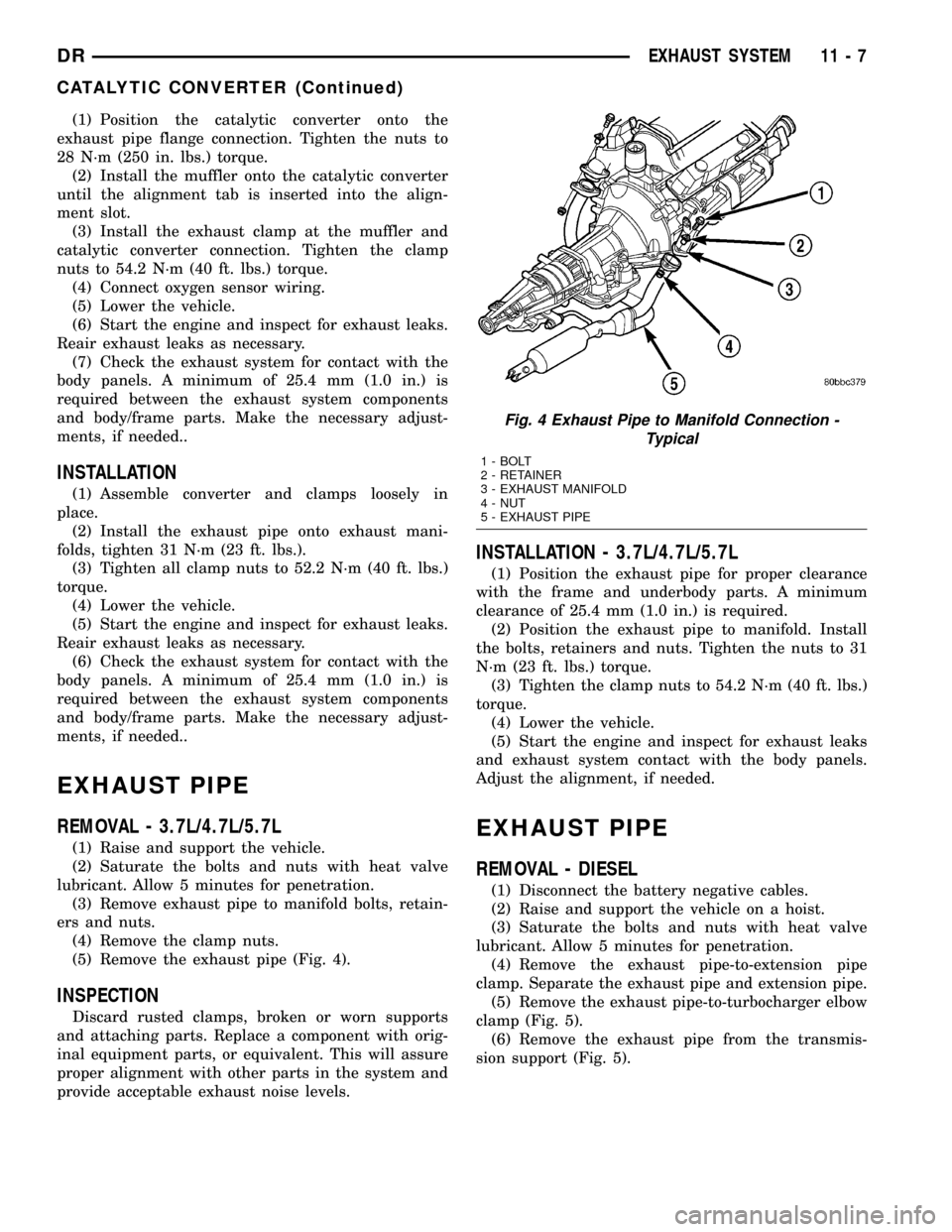
(5) Remove the exhaust pipe (Fig. 4).
INSPECTION
Discard rusted clamps, broken or worn supports
and attaching parts. Replace a component with orig-
inal equipment parts, or equivalent. This will assure
proper alignment with other parts in the system and
provide acceptable exhaust noise levels.
INSTALLATION - 3.7L/4.7L/5.7L
(1) Position the exhaust pipe for proper clearance
with the frame and underbody parts. A minimum
clearance of 25.4 mm (1.0 in.) is required.
(2) Position the exhaust pipe to manifold. Install
the bolts, retainers and nuts. Tighten the nuts to 31
N´m (23 ft. lbs.) torque.
(3) Tighten the clamp nuts to 54.2 N´m (40 ft. lbs.)
torque.
(4) Lower the vehicle.
(5) Start the engine and inspect for exhaust leaks
and exhaust system contact with the body panels.
Adjust the alignment, if needed.
EXHAUST PIPE
REMOVAL - DIESEL
(1) Disconnect the battery negative cables.
(2) Raise and support the vehicle on a hoist.
(3) Saturate the bolts and nuts with heat valve
lubricant. Allow 5 minutes for penetration.
(4) Remove the exhaust pipe-to-extension pipe
clamp. Separate the exhaust pipe and extension pipe.
(5) Remove the exhaust pipe-to-turbocharger elbow
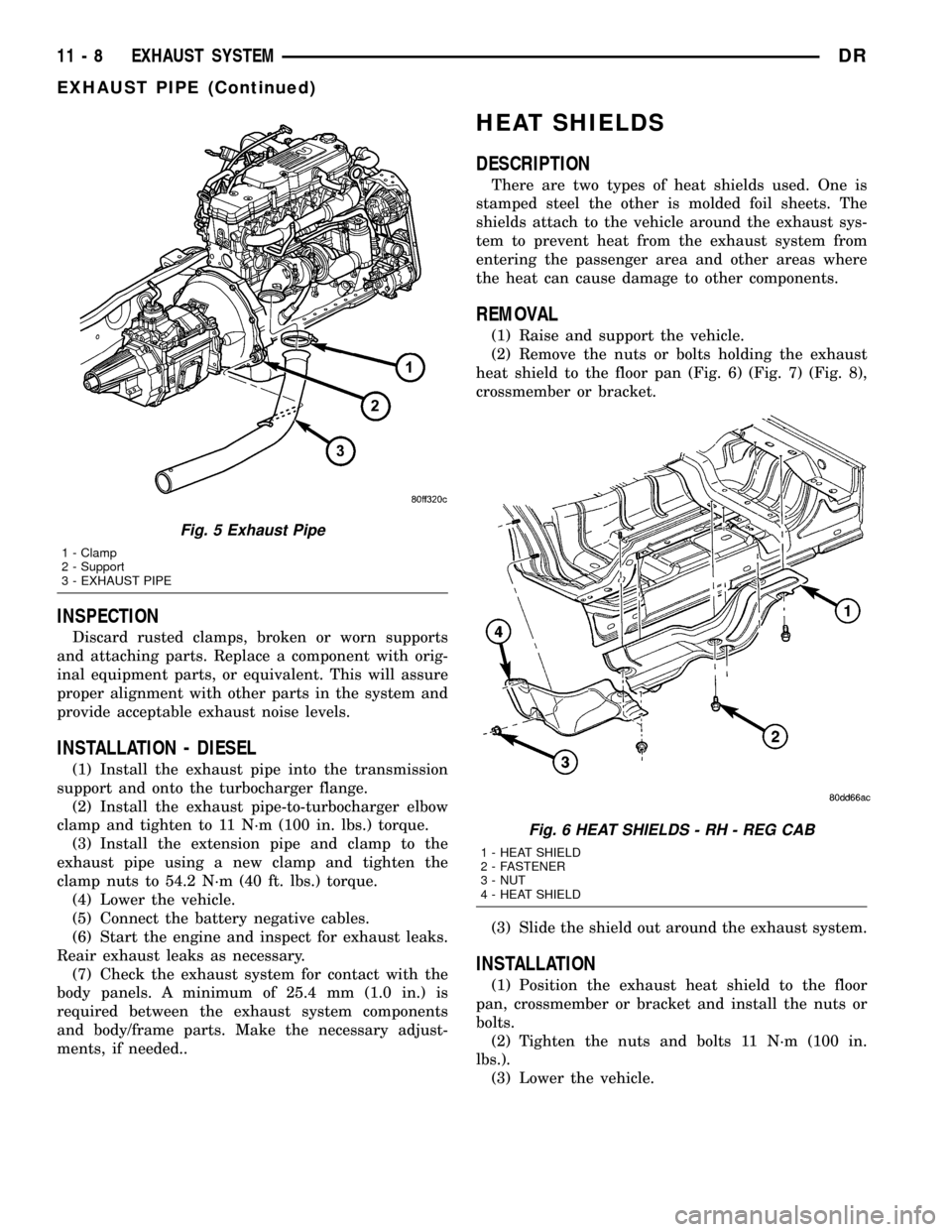
clamp (Fig. 5).
(6) Remove the exhaust pipe from the transmis-
sion support (Fig. 5).
Fig. 4 Exhaust Pipe to Manifold Connection -
Typical
1 - BOLT
2 - RETAINER
3 - EXHAUST MANIFOLD
4 - NUT
5 - EXHAUST PIPE
DREXHAUST SYSTEM 11 - 7
CATALYTIC CONVERTER (Continued)
Page 1533 of 2627
INSPECTION
Discard rusted clamps, broken or worn supports
and attaching parts. Replace a component with orig-
inal equipment parts, or equivalent. This will assure
proper alignment with other parts in the system and
provide acceptable exhaust noise levels.
INSTALLATION - DIESEL
(1) Install the exhaust pipe into the transmission
support and onto the turbocharger flange.
(2) Install the exhaust pipe-to-turbocharger elbow
clamp and tighten to 11 N´m (100 in. lbs.) torque.
(3) Install the extension pipe and clamp to the
exhaust pipe using a new clamp and tighten the
clamp nuts to 54.2 N´m (40 ft. lbs.) torque.
(4) Lower the vehicle.
(5) Connect the battery negative cables.
(6) Start the engine and inspect for exhaust leaks.
Reair exhaust leaks as necessary.
(7) Check the exhaust system for contact with the
body panels. A minimum of 25.4 mm (1.0 in.) is
required between the exhaust system components
and body/frame parts. Make the necessary adjust-
ments, if needed..
HEAT SHIELDS
DESCRIPTION
There are two types of heat shields used. One is
stamped steel the other is molded foil sheets. The
shields attach to the vehicle around the exhaust sys-
tem to prevent heat from the exhaust system from
entering the passenger area and other areas where
the heat can cause damage to other components.
REMOVAL
(1) Raise and support the vehicle.
(2) Remove the nuts or bolts holding the exhaust
heat shield to the floor pan (Fig. 6) (Fig. 7) (Fig. 8),
crossmember or bracket.
(3) Slide the shield out around the exhaust system.
INSTALLATION
(1) Position the exhaust heat shield to the floor
pan, crossmember or bracket and install the nuts or
bolts.
(2) Tighten the nuts and bolts 11 N´m (100 in.
lbs.).
(3) Lower the vehicle.
Fig. 5 Exhaust Pipe
1 - Clamp
2 - Support
3 - EXHAUST PIPE
Fig. 6 HEAT SHIELDS - RH - REG CAB
1 - HEAT SHIELD
2 - FASTENER
3 - NUT
4 - HEAT SHIELD
11 - 8 EXHAUST SYSTEMDR
EXHAUST PIPE (Continued)
Page 1534 of 2627
MUFFLER
REMOVAL
(1) Raise and support the vehicle.
(2) Saturate the clamp nuts with heat valve lubri-
cant. Allow 5 minutes for penetration.
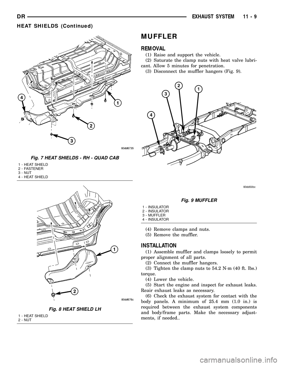
(3) Disconnect the muffler hangers (Fig. 9).
(4) Remove clamps and nuts.
(5) Remove the muffler.
INSTALLATION
(1) Assemble muffler and clamps loosely to permit
proper alignment of all parts.
(2) Connect the muffler hangers.
(3) Tighten the clamp nuts to 54.2 N´m (40 ft. lbs.)
torque.
(4) Lower the vehicle.
(5) Start the engine and inspect for exhaust leaks.
Reair exhaust leaks as necessary.
(6) Check the exhaust system for contact with the
body panels. A minimum of 25.4 mm (1.0 in.) is
required between the exhaust system components
and body/frame parts. Make the necessary adjust-
ments, if needed..
Fig. 7 HEAT SHIELDS - RH - QUAD CAB
1 - HEAT SHIELD
2 - FASTENER
3 - NUT
4 - HEAT SHIELD
Fig. 8 HEAT SHIELD LH
1 - HEAT SHIELD
2 - NUT
Fig. 9 MUFFLER
1 - INSULATOR
2 - INSULATOR
3 - MUFFLER
4 - INSULATOR
DREXHAUST SYSTEM 11 - 9
HEAT SHIELDS (Continued)
Page 1535 of 2627
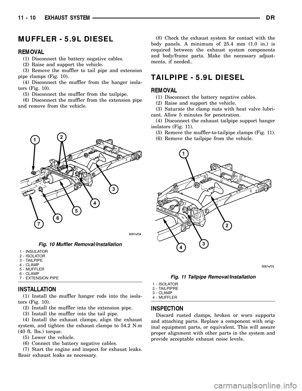
MUFFLER - 5.9L DIESEL
REMOVAL
(1) Disconnect the battery negative cables.
(2) Raise and support the vehicle.
(3) Remove the muffler to tail pipe and extension
pipe clamps (Fig. 10).
(4) Disconnect the muffler from the hanger isola-
tors (Fig. 10).
(5) Disconnect the muffler from the tailpipe.
(6) Disconnect the muffler from the extension pipe
and remove from the vehicle.
INSTALLATION
(1) Install the muffler hanger rods into the isola-
tors (Fig. 10).
(2) Install the muffler into the extension pipe.
(3) Install the muffler into the tail pipe.
(4) Install the exhaust clamps, align the exhaust
system, and tighten the exhaust clamps to 54.2 N´m
(40 ft. lbs.) torque.
(5) Lower the vehicle.
(6) Connect the battery negative cables.
(7) Start the engine and inspect for exhaust leaks.
Reair exhaust leaks as necessary.(8) Check the exhaust system for contact with the
body panels. A minimum of 25.4 mm (1.0 in.) is
required between the exhaust system components
and body/frame parts. Make the necessary adjust-
ments, if needed..
TAILPIPE - 5.9L DIESEL
REMOVAL
(1) Disconnect the battery negative cables.
(2) Raise and support the vehicle.
(3) Saturate the clamp nuts with heat valve lubri-
cant. Allow 5 minutes for penetration.
(4) Disconnect the exhaust tailpipe support hanger
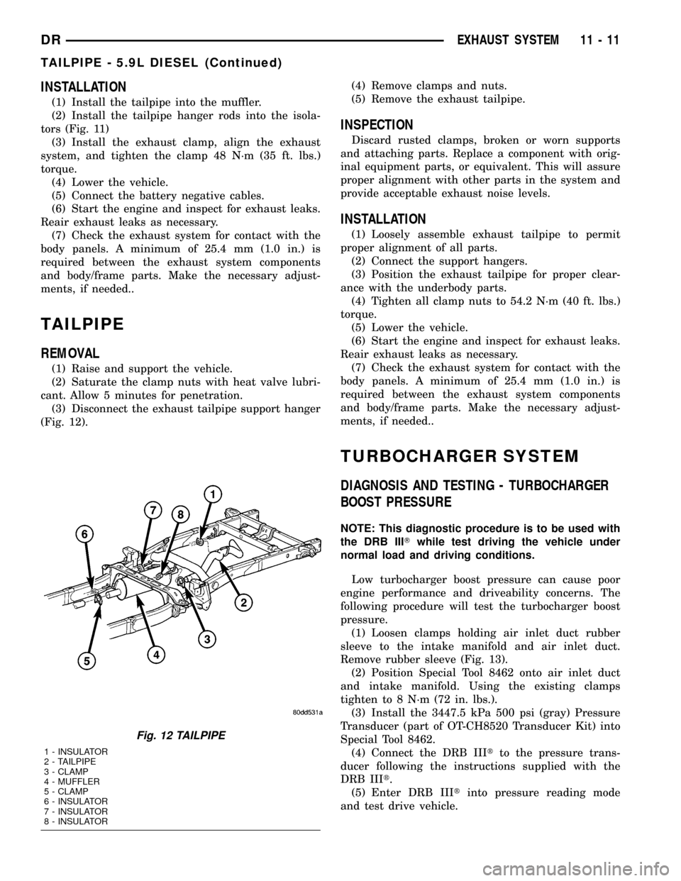
isolators (Fig. 11).
(5) Remove the muffler-to-tailpipe clamps (Fig. 11).
(6) Remove the tailpipe from the vehicle.
INSPECTION
Discard rusted clamps, broken or worn supports
and attaching parts. Replace a component with orig-
inal equipment parts, or equivalent. This will assure
proper alignment with other parts in the system and
provide acceptable exhaust noise levels.
Fig. 10 Muffler Removal/Installation
1 - INSULATOR
2 - ISOLATOR
3 - TAILPIPE
4 - CLAMP
5 - MUFFLER
6 - CLAMP
7 - EXTENSION PIPE
Fig. 11 Tailpipe Removal/Installation
1 - ISOLATOR
2 - TAILPIPRE
3 - CLAMP
4 - MUFFLER
11 - 10 EXHAUST SYSTEMDR
Page 1536 of 2627
INSTALLATION
(1) Install the tailpipe into the muffler.
(2) Install the tailpipe hanger rods into the isola-
tors (Fig. 11)
(3) Install the exhaust clamp, align the exhaust
system, and tighten the clamp 48 N´m (35 ft. lbs.)
torque.
(4) Lower the vehicle.
(5) Connect the battery negative cables.
(6) Start the engine and inspect for exhaust leaks.
Reair exhaust leaks as necessary.
(7) Check the exhaust system for contact with the
body panels. A minimum of 25.4 mm (1.0 in.) is
required between the exhaust system components
and body/frame parts. Make the necessary adjust-
ments, if needed..
TAILPIPE
REMOVAL
(1) Raise and support the vehicle.
(2) Saturate the clamp nuts with heat valve lubri-
cant. Allow 5 minutes for penetration.
(3) Disconnect the exhaust tailpipe support hanger
(Fig. 12).(4) Remove clamps and nuts.
(5) Remove the exhaust tailpipe.
INSPECTION
Discard rusted clamps, broken or worn supports
and attaching parts. Replace a component with orig-
inal equipment parts, or equivalent. This will assure
proper alignment with other parts in the system and
provide acceptable exhaust noise levels.
INSTALLATION
(1) Loosely assemble exhaust tailpipe to permit
proper alignment of all parts.
(2) Connect the support hangers.
(3) Position the exhaust tailpipe for proper clear-
ance with the underbody parts.
(4) Tighten all clamp nuts to 54.2 N´m (40 ft. lbs.)
torque.
(5) Lower the vehicle.
(6) Start the engine and inspect for exhaust leaks.
Reair exhaust leaks as necessary.
(7) Check the exhaust system for contact with the
body panels. A minimum of 25.4 mm (1.0 in.) is
required between the exhaust system components
and body/frame parts. Make the necessary adjust-
ments, if needed..
TURBOCHARGER SYSTEM
DIAGNOSIS AND TESTING - TURBOCHARGER
BOOST PRESSURE
NOTE: This diagnostic procedure is to be used with
the DRB IIITwhile test driving the vehicle under
normal load and driving conditions.
Low turbocharger boost pressure can cause poor
engine performance and driveability concerns. The
following procedure will test the turbocharger boost
pressure.
(1) Loosen clamps holding air inlet duct rubber
sleeve to the intake manifold and air inlet duct.
Remove rubber sleeve (Fig. 13).
(2) Position Special Tool 8462 onto air inlet duct
and intake manifold. Using the existing clamps
tighten to 8 N´m (72 in. lbs.).
(3) Install the 3447.5 kPa 500 psi (gray) Pressure
Transducer (part of OT-CH8520 Transducer Kit) into
Special Tool 8462.
(4) Connect the DRB IIItto the pressure trans-
ducer following the instructions supplied with the
DRB IIIt.
(5) Enter DRB IIItinto pressure reading mode
and test drive vehicle.
Fig. 12 TAILPIPE
1 - INSULATOR
2 - TAILPIPE
3 - CLAMP
4 - MUFFLER
5 - CLAMP
6 - INSULATOR
7 - INSULATOR
8 - INSULATOR
DREXHAUST SYSTEM 11 - 11
TAILPIPE - 5.9L DIESEL (Continued)
Page 1539 of 2627
TURBOCHARGER(COOL DOWN(CHART
Driving
ConditionLoad Turbo-
charger
Temper-
atureIdle Time (in
minutes)
Before Shut
Down
Stop & Go Empty Cool Less than 1
Stop & Go Medium Warm 1
Highway
SpeedsMedium Warm 2
City Traffic Max.
GCWRWarm 3
Highway
SpeedsMax.
GCWRWarm 4
Uphill Grade Max.
GCWRHot 5
REMOVAL
(1) Disconnect the battery negative cables.
(2) Raise vehicle on hoist.
(3) Disconnect the exhaust pipe from the turbo-
charger elbow(Refer to 11 - EXHAUST SYSTEM/EX-
HAUST PIPE - REMOVAL).
(4) Remove the bolts from the turbocharger oil
drain tube.
(5) Lower vehicle.
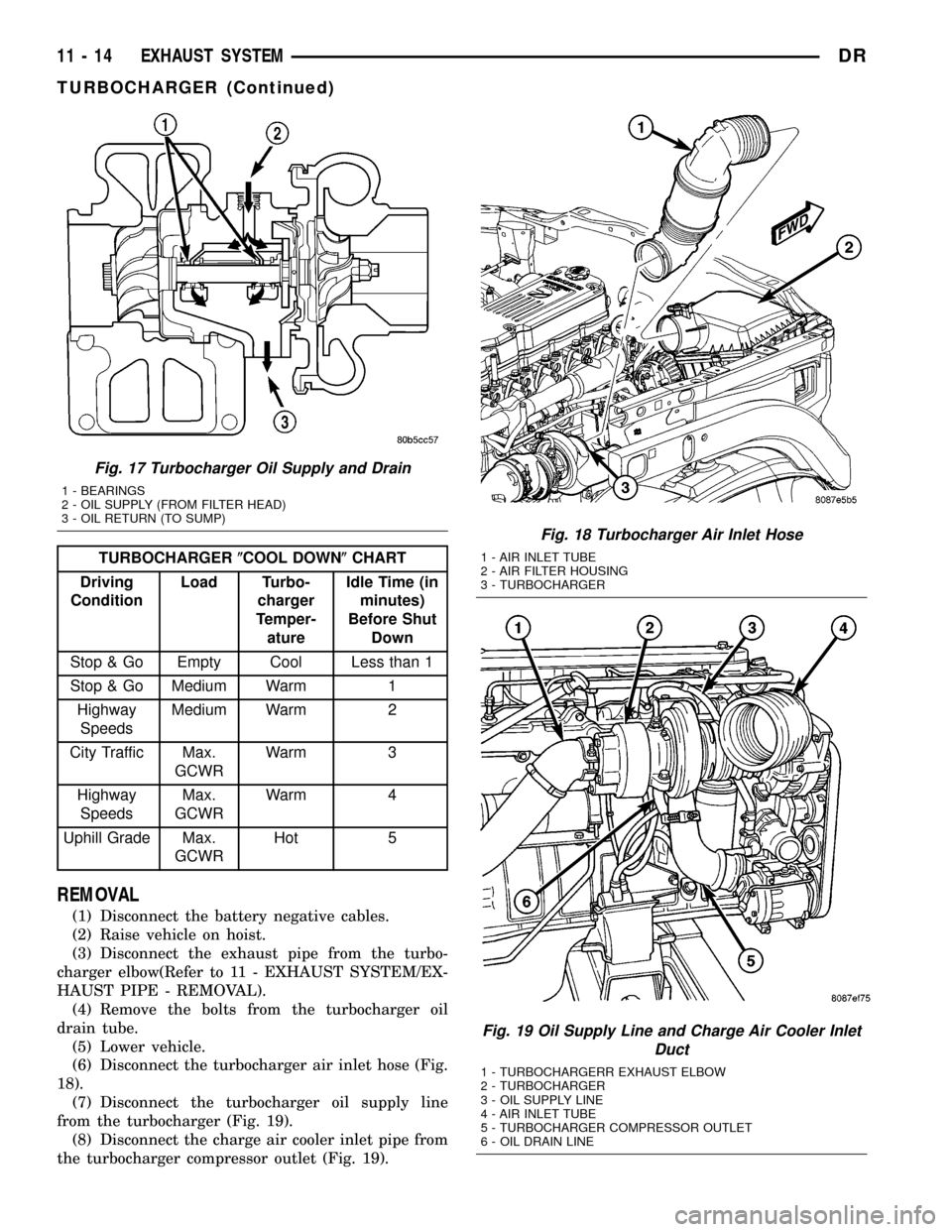
(6) Disconnect the turbocharger air inlet hose (Fig.
18).
(7) Disconnect the turbocharger oil supply line
from the turbocharger (Fig. 19).
(8) Disconnect the charge air cooler inlet pipe from
the turbocharger compressor outlet (Fig. 19).
Fig. 17 Turbocharger Oil Supply and Drain
1 - BEARINGS
2 - OIL SUPPLY (FROM FILTER HEAD)
3 - OIL RETURN (TO SUMP)
Fig. 18 Turbocharger Air Inlet Hose
1 - AIR INLET TUBE
2 - AIR FILTER HOUSING
3 - TURBOCHARGER
Fig. 19 Oil Supply Line and Charge Air Cooler Inlet
Duct
1 - TURBOCHARGERR EXHAUST ELBOW
2 - TURBOCHARGER
3 - OIL SUPPLY LINE
4 - AIR INLET TUBE
5 - TURBOCHARGER COMPRESSOR OUTLET
6 - OIL DRAIN LINE
11 - 14 EXHAUST SYSTEMDR
TURBOCHARGER (Continued)
Page 1542 of 2627
CAUTION: Do not apply more than 138 kPa (20 psi)
air pressure to the charge air cooler system, sever
damage to the charge air cooler system may occur.
(3) Connect a regulated air supply to air fitting on
Tool 9022 Adapter. Set air pressure to a Maximum of
138 kPa (20 psi).
(4) Using soapy water check the rubber sleeves,
charge air cooler and intake manifold for leaks.
REMOVAL
WARNING: IF THE ENGINE WAS JUST TURNED
OFF, THE AIR INTAKE SYSTEM TUBES MAY BE
HOT.
(1) Disconnect the battery negative cables.
(2) Discharge the A/C system (Refer to 24 - HEAT-
ING & AIR CONDITIONING/PLUMBING - STAN-
DARD PROCEDURE) and remove the A/C condenser
(Refer to 24 - HEATING & AIR CONDITIONING/
PLUMBING/A/C CONDENSER - REMOVAL) (if A/C
equipped).
(3) Remove the transmission auxiliary cooler
(Refer to 7 - COOLING/TRANSMISSION/TRANS
COOLER - REMOVAL).
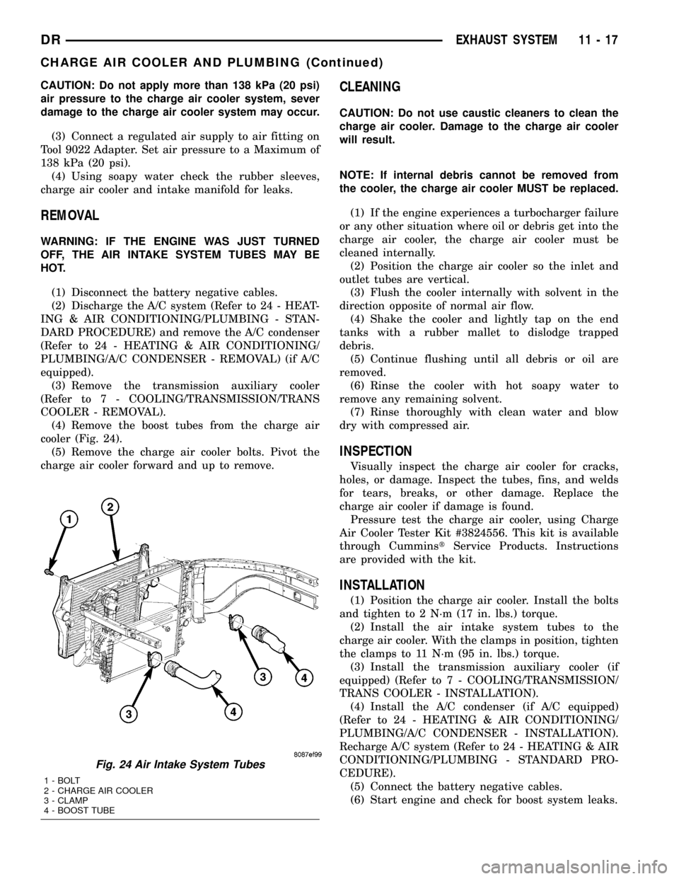
(4) Remove the boost tubes from the charge air
cooler (Fig. 24).
(5) Remove the charge air cooler bolts. Pivot the
charge air cooler forward and up to remove.
CLEANING
CAUTION: Do not use caustic cleaners to clean the
charge air cooler. Damage to the charge air cooler
will result.
NOTE: If internal debris cannot be removed from
the cooler, the charge air cooler MUST be replaced.
(1) If the engine experiences a turbocharger failure
or any other situation where oil or debris get into the
charge air cooler, the charge air cooler must be
cleaned internally.
(2) Position the charge air cooler so the inlet and
outlet tubes are vertical.
(3) Flush the cooler internally with solvent in the
direction opposite of normal air flow.
(4) Shake the cooler and lightly tap on the end
tanks with a rubber mallet to dislodge trapped
debris.
(5) Continue flushing until all debris or oil are
removed.
(6) Rinse the cooler with hot soapy water to
remove any remaining solvent.
(7) Rinse thoroughly with clean water and blow
dry with compressed air.
INSPECTION
Visually inspect the charge air cooler for cracks,
holes, or damage. Inspect the tubes, fins, and welds
for tears, breaks, or other damage. Replace the
charge air cooler if damage is found.
Pressure test the charge air cooler, using Charge
Air Cooler Tester Kit #3824556. This kit is available
through CumminstService Products. Instructions
are provided with the kit.
INSTALLATION
(1) Position the charge air cooler. Install the bolts
and tighten to 2 N´m (17 in. lbs.) torque.
(2) Install the air intake system tubes to the
charge air cooler. With the clamps in position, tighten
the clamps to 11 N´m (95 in. lbs.) torque.
(3) Install the transmission auxiliary cooler (if
equipped) (Refer to 7 - COOLING/TRANSMISSION/
TRANS COOLER - INSTALLATION).
(4) Install the A/C condenser (if A/C equipped)
(Refer to 24 - HEATING & AIR CONDITIONING/
PLUMBING/A/C CONDENSER - INSTALLATION).
Recharge A/C system (Refer to 24 - HEATING & AIR
CONDITIONING/PLUMBING - STANDARD PRO-
CEDURE).
(5) Connect the battery negative cables.
(6) Start engine and check for boost system leaks.
Fig. 24 Air Intake System Tubes
1 - BOLT
2 - CHARGE AIR COOLER
3 - CLAMP
4 - BOOST TUBE
DREXHAUST SYSTEM 11 - 17
CHARGE AIR COOLER AND PLUMBING (Continued)
Page 1544 of 2627
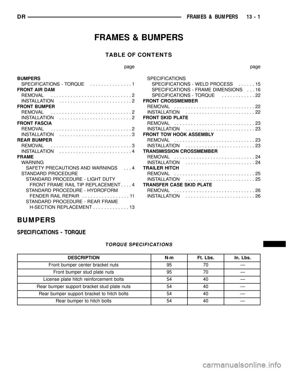
FRAMES & BUMPERS
TABLE OF CONTENTS
page page
BUMPERS
SPECIFICATIONS - TORQUE...............1
FRONT AIR DAM
REMOVAL.............................2
INSTALLATION..........................2
FRONT BUMPER
REMOVAL.............................2
INSTALLATION..........................2
FRONT FASCIA
REMOVAL.............................2
INSTALLATION..........................3
REAR BUMPER
REMOVAL.............................3
INSTALLATION..........................4
FRAME
WARNING
SAFETY PRECAUTIONS AND WARNINGS . . . 4
STANDARD PROCEDURE
STANDARD PROCEDURE - LIGHT DUTY
FRONT FRAME RAIL TIP REPLACEMENT....4
STANDARD PROCEDURE - HYDROFORM
FENDER RAIL REPAIR.................11
STANDARD PROCEDURE - REAR FRAME
H-SECTION REPLACEMENT.............13SPECIFICATIONS
SPECIFICATIONS - WELD PROCESS......15
SPECIFICATIONS - FRAME DIMENSIONS . . . 16
SPECIFICATIONS - TORQUE............22
FRONT CROSSMEMBER
REMOVAL.............................22
INSTALLATION.........................22
FRONT SKID PLATE
REMOVAL.............................23
INSTALLATION.........................23
FRONT TOW HOOK ASSEMBLY
REMOVAL.............................23
INSTALLATION.........................23
TRANSMISSION CROSSMEMBER
REMOVAL.............................24
INSTALLATION.........................24
TRAILER HITCH
REMOVAL.............................25
INSTALLATION.........................25
TRANSFER CASE SKID PLATE
REMOVAL.............................26
INSTALLATION.........................26
BUMPERS
SPECIFICATIONS - TORQUE
TORQUE SPECIFICATIONS
DESCRIPTION N´m Ft. Lbs. In. Lbs.
Front bumper center bracket nuts 95 70 Ð
Front bumper stud plate nuts 95 70 Ð
License plate hitch reinforcement bolts 54 40 Ð
Rear bumper support bracket stud plate nuts 54 40 Ð
Rear bumper support bracket to hitch bolts 54 40 Ð
Rear bumper to hitch bolts 54 40 Ð
DRFRAMES & BUMPERS 13 - 1
Page 1545 of 2627
FRONT AIR DAM
REMOVAL
(1) Remove the two outboard screws.
(2) Remove the three middle screws and remove
the air dam.
INSTALLATION
(1) Position the air dam onto the bumper and seat
the carrot type fasteners fully.
(2) Starting at the center screw install the three
middle screws.
(3) Install the two outboard screws.
FRONT BUMPER
REMOVAL
(1) Using a grease pencil or equivalent, mark the
position of the bumper on the frame rail tip to aid
installation.
(2) Disconnect the fog lamp electrical connector at
the left frame rail.
(3) Support the bumper with a suitable lifting
device.
(4) Remove the center bracket nuts and bolts and
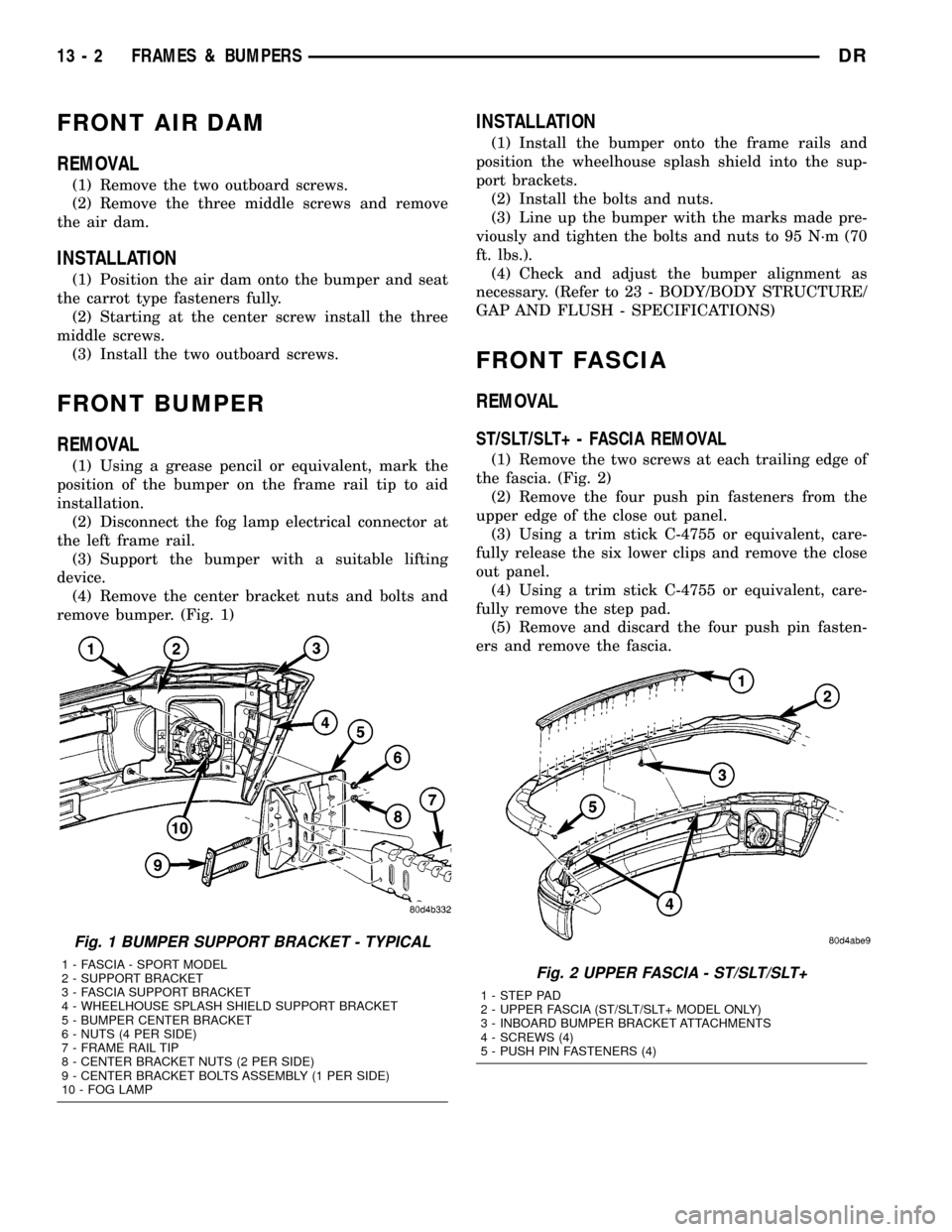
remove bumper. (Fig. 1)
INSTALLATION
(1) Install the bumper onto the frame rails and
position the wheelhouse splash shield into the sup-
port brackets.
(2) Install the bolts and nuts.
(3) Line up the bumper with the marks made pre-
viously and tighten the bolts and nuts to 95 N´m (70
ft. lbs.).
(4) Check and adjust the bumper alignment as
necessary. (Refer to 23 - BODY/BODY STRUCTURE/
GAP AND FLUSH - SPECIFICATIONS)
FRONT FASCIA
REMOVAL
ST/SLT/SLT+ - FASCIA REMOVAL
(1) Remove the two screws at each trailing edge of
the fascia. (Fig. 2)
(2) Remove the four push pin fasteners from the
upper edge of the close out panel.
(3) Using a trim stick C-4755 or equivalent, care-
fully release the six lower clips and remove the close
out panel.
(4) Using a trim stick C-4755 or equivalent, care-
fully remove the step pad.
(5) Remove and discard the four push pin fasten-
ers and remove the fascia.
Fig. 1 BUMPER SUPPORT BRACKET - TYPICAL
1 - FASCIA - SPORT MODEL
2 - SUPPORT BRACKET
3 - FASCIA SUPPORT BRACKET
4 - WHEELHOUSE SPLASH SHIELD SUPPORT BRACKET
5 - BUMPER CENTER BRACKET
6 - NUTS (4 PER SIDE)
7 - FRAME RAIL TIP
8 - CENTER BRACKET NUTS (2 PER SIDE)
9 - CENTER BRACKET BOLTS ASSEMBLY (1 PER SIDE)
10 - FOG LAMPFig. 2 UPPER FASCIA - ST/SLT/SLT+
1 - STEP PAD
2 - UPPER FASCIA (ST/SLT/SLT+ MODEL ONLY)
3 - INBOARD BUMPER BRACKET ATTACHMENTS
4 - SCREWS (4)
5 - PUSH PIN FASTENERS (4)
13 - 2 FRAMES & BUMPERSDR