Alignment DODGE RAM 1500 1998 2.G Repair Manual
[x] Cancel search | Manufacturer: DODGE, Model Year: 1998, Model line: RAM 1500, Model: DODGE RAM 1500 1998 2.GPages: 2627
Page 639 of 2627
from the centered position, without damaging the
clockspring tape.
However, if the clockspring is removed for service
or if the steering column is disconnected from the
steering gear, the clockspring tape can change posi-
tion relative to the other steering components. The
clockspring must then be re-centered following com-
pletion of such service or the clockspring tape may be
damaged. Service replacement clocksprings are
shipped pre-centered, with a molded plastic locking
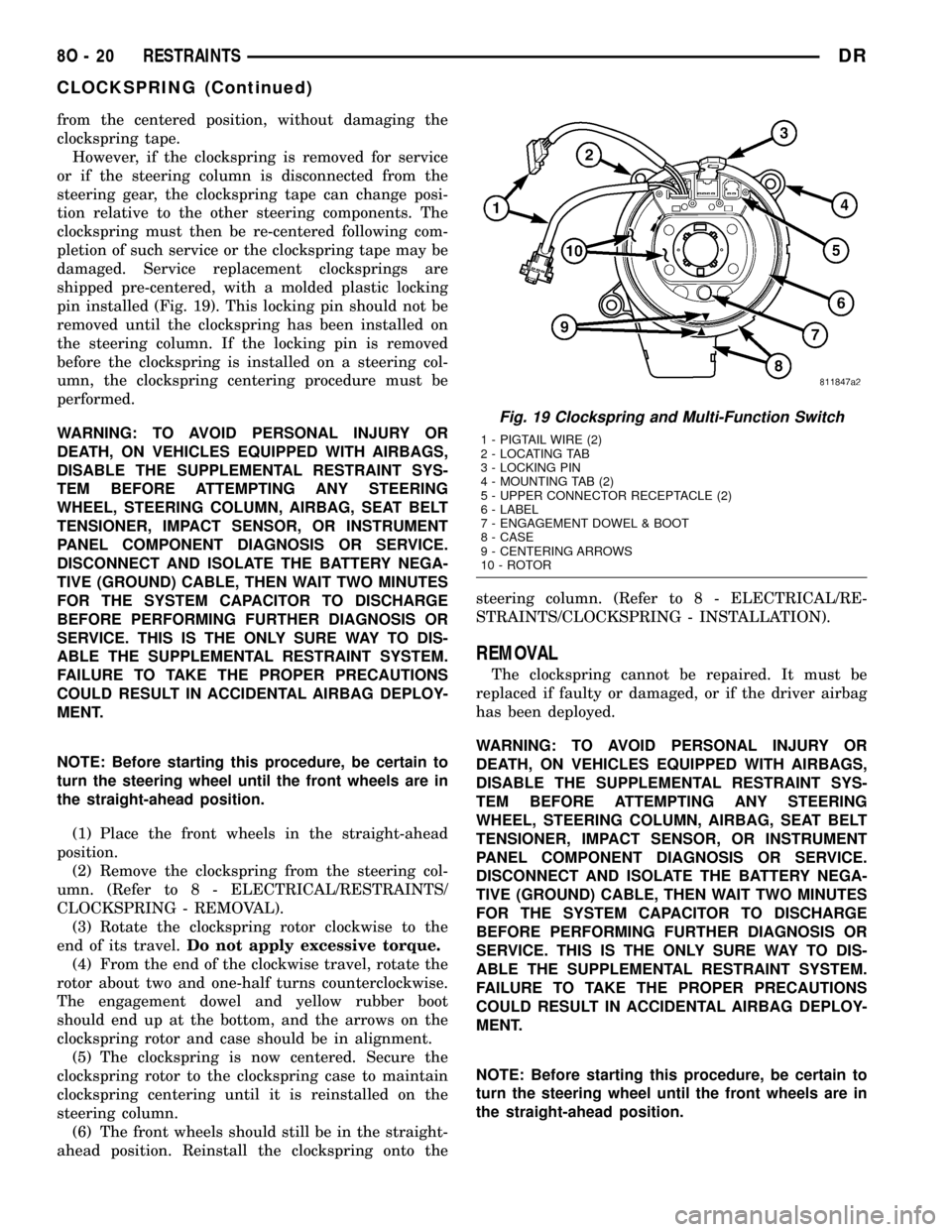
pin installed (Fig. 19). This locking pin should not be
removed until the clockspring has been installed on
the steering column. If the locking pin is removed
before the clockspring is installed on a steering col-
umn, the clockspring centering procedure must be
performed.
WARNING: TO AVOID PERSONAL INJURY OR
DEATH, ON VEHICLES EQUIPPED WITH AIRBAGS,
DISABLE THE SUPPLEMENTAL RESTRAINT SYS-
TEM BEFORE ATTEMPTING ANY STEERING
WHEEL, STEERING COLUMN, AIRBAG, SEAT BELT
TENSIONER, IMPACT SENSOR, OR INSTRUMENT
PANEL COMPONENT DIAGNOSIS OR SERVICE.
DISCONNECT AND ISOLATE THE BATTERY NEGA-
TIVE (GROUND) CABLE, THEN WAIT TWO MINUTES
FOR THE SYSTEM CAPACITOR TO DISCHARGE
BEFORE PERFORMING FURTHER DIAGNOSIS OR
SERVICE. THIS IS THE ONLY SURE WAY TO DIS-
ABLE THE SUPPLEMENTAL RESTRAINT SYSTEM.
FAILURE TO TAKE THE PROPER PRECAUTIONS
COULD RESULT IN ACCIDENTAL AIRBAG DEPLOY-
MENT.
NOTE: Before starting this procedure, be certain to
turn the steering wheel until the front wheels are in
the straight-ahead position.
(1) Place the front wheels in the straight-ahead
position.
(2) Remove the clockspring from the steering col-
umn. (Refer to 8 - ELECTRICAL/RESTRAINTS/
CLOCKSPRING - REMOVAL).
(3) Rotate the clockspring rotor clockwise to the
end of its travel.Do not apply excessive torque.
(4) From the end of the clockwise travel, rotate the
rotor about two and one-half turns counterclockwise.
The engagement dowel and yellow rubber boot
should end up at the bottom, and the arrows on the
clockspring rotor and case should be in alignment.
(5) The clockspring is now centered. Secure the
clockspring rotor to the clockspring case to maintain
clockspring centering until it is reinstalled on the
steering column.
(6) The front wheels should still be in the straight-
ahead position. Reinstall the clockspring onto thesteering column. (Refer to 8 - ELECTRICAL/RE-
STRAINTS/CLOCKSPRING - INSTALLATION).
REMOVAL
The clockspring cannot be repaired. It must be
replaced if faulty or damaged, or if the driver airbag
has been deployed.
WARNING: TO AVOID PERSONAL INJURY OR
DEATH, ON VEHICLES EQUIPPED WITH AIRBAGS,
DISABLE THE SUPPLEMENTAL RESTRAINT SYS-
TEM BEFORE ATTEMPTING ANY STEERING
WHEEL, STEERING COLUMN, AIRBAG, SEAT BELT
TENSIONER, IMPACT SENSOR, OR INSTRUMENT
PANEL COMPONENT DIAGNOSIS OR SERVICE.
DISCONNECT AND ISOLATE THE BATTERY NEGA-
TIVE (GROUND) CABLE, THEN WAIT TWO MINUTES
FOR THE SYSTEM CAPACITOR TO DISCHARGE
BEFORE PERFORMING FURTHER DIAGNOSIS OR
SERVICE. THIS IS THE ONLY SURE WAY TO DIS-
ABLE THE SUPPLEMENTAL RESTRAINT SYSTEM.
FAILURE TO TAKE THE PROPER PRECAUTIONS
COULD RESULT IN ACCIDENTAL AIRBAG DEPLOY-
MENT.
NOTE: Before starting this procedure, be certain to
turn the steering wheel until the front wheels are in
the straight-ahead position.
Fig. 19 Clockspring and Multi-Function Switch
1 - PIGTAIL WIRE (2)
2 - LOCATING TAB
3 - LOCKING PIN
4 - MOUNTING TAB (2)
5 - UPPER CONNECTOR RECEPTACLE (2)
6 - LABEL
7 - ENGAGEMENT DOWEL & BOOT
8 - CASE
9 - CENTERING ARROWS
10 - ROTOR
8O - 20 RESTRAINTSDR
CLOCKSPRING (Continued)
Page 715 of 2627
plenum cover/grille panel near the base of the wind-
shield and the wiper blades on the windshield glass
(Fig. 18). These wiper arms feature an over-center
hinge that allows easy access to the windshield glass
for cleaning. The wiper arm has a die cast metal
pivot end with a large internally serrated socket for-
mation at one end. A key within the socket formation
indexes the wiper arm to a keyway in the pivot shaft
of the wiper module to provide wiper alignment, and
a spring-loaded latch on the underside of the wiper
arm pivot end locks the unit to the pivot shaft when
it is fully installed. The right and left wiper arms for
this model are not interchangeable, as the right
wiper arm is slightly longer than the left one.
The wide end of a tapered, stamped steel channel
hinges on and is secured with a hinge pin to the
blade end of the wiper arm pivot end. One end of a
long, rigid, stamped steel strap, with a small hole
near its pivot end, is riveted and crimped within the
narrow end of the stamped steel channel. The tip of
the wiper blade end of this strap is bent back under
itself to form a small hook. Concealed within the
stamped steel channel, one end of a long spring is
engaged with a wire hook on the underside of the die
cast pivot end, while the other end of the spring is
hooked through the small hole in the steel strap. The
entire wiper arm has a satin black finish applied to
all of its visible surfaces.
A wiper arm cannot be adjusted or repaired. If
damaged or faulty, the entire wiper arm unit must be
replaced.
OPERATION
The wiper arms are designed to mechanically
transmit the motion from the wiper pivots to the
wiper blades. The wiper arm must be properly
indexed to the wiper pivot in order to maintain the
proper wiper blade travel on the glass. The serrated
and keyed socket formation in the wiper arm pivot
end interlocks with the serrations and keyway on the
outer circumference of the wiper pivot shaft, provid-
ing positive engagement and alignment of this con-
nection. The latch positively locks the wiper arm to
the wiper pivot shaft when the arm is fully installed.
The spring-loaded wiper arm hinge controls the
down-force applied through the tip of the wiper arm
to the wiper blade on the glass. The hook formation
on the tip of the wiper arm provides a cradle for
securing and latching the wiper blade pivot block to
the wiper arm.
REMOVAL
(1) Lift the wiper arm to its over-center position to
hold the wiper blade off of the glass and relieve the
spring tension on the wiper arm to wiper pivot shaft
connection.(2) Pull the latch on the pivot end of the wiper
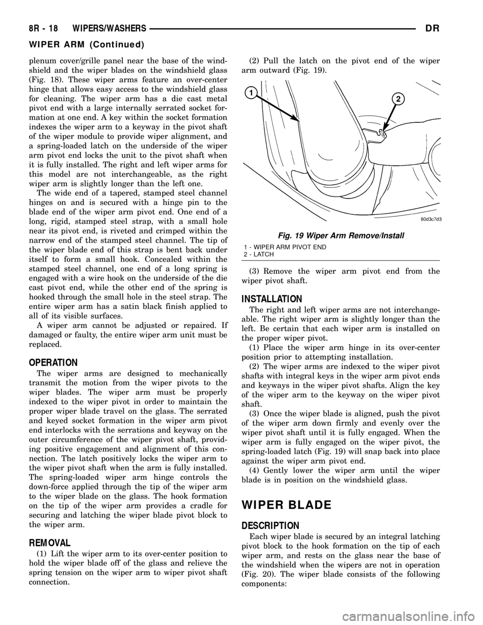
arm outward (Fig. 19).
(3) Remove the wiper arm pivot end from the
wiper pivot shaft.
INSTALLATION
The right and left wiper arms are not interchange-
able. The right wiper arm is slightly longer than the
left. Be certain that each wiper arm is installed on
the proper wiper pivot.
(1) Place the wiper arm hinge in its over-center
position prior to attempting installation.
(2) The wiper arms are indexed to the wiper pivot
shafts with integral keys in the wiper arm pivot ends
and keyways in the wiper pivot shafts. Align the key
of the wiper arm to the keyway on the wiper pivot
shaft.
(3) Once the wiper blade is aligned, push the pivot
of the wiper arm down firmly and evenly over the
wiper pivot shaft until it is fully engaged. When the
wiper arm is fully engaged on the wiper pivot, the
spring-loaded latch (Fig. 19) will snap back into place
against the wiper arm pivot end.
(4) Gently lower the wiper arm until the wiper
blade is in position on the windshield glass.
WIPER BLADE
DESCRIPTION
Each wiper blade is secured by an integral latching
pivot block to the hook formation on the tip of each
wiper arm, and rests on the glass near the base of
the windshield when the wipers are not in operation
(Fig. 20). The wiper blade consists of the following
components:
Fig. 19 Wiper Arm Remove/Install
1 - WIPER ARM PIVOT END
2-LATCH
8R - 18 WIPERS/WASHERSDR
WIPER ARM (Continued)
Page 1272 of 2627
STANDARD PROCEDURE
CONNECTING ROD BEARING FITTING
Inspect the connecting rod bearings for scoring.
Check the bearings for normal wear patterns, scor-
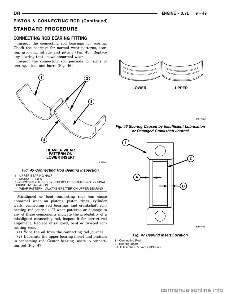
ing, grooving, fatigue and pitting (Fig. 45). Replace
any bearing that shows abnormal wear.
Inspect the connecting rod journals for signs of
scoring, nicks and burrs (Fig. 46).
Misaligned or bent connecting rods can cause
abnormal wear on pistons, piston rings, cylinder
walls, connecting rod bearings and crankshaft con-
necting rod journals. If wear patterns or damage to
any of these components indicate the probability of a
misaligned connecting rod, inspect it for correct rod
alignment. Replace misaligned, bent or twisted con-
necting rods.
(1) Wipe the oil from the connecting rod journal.
(2) Lubricate the upper bearing insert and position
in connecting rod. Center bearing insert in connect-
ing rod (Fig. 47)
Fig. 45 Connecting Rod Bearing Inspection
1 - UPPER BEARING HALF
2 - MATING EDGES
3 - GROOVES CAUSED BY ROD BOLTS SCRATCHING JOURNAL
DURING INSTALLATION
4 - WEAR PATTERN - ALWAYS GREATER ON UPPER BEARING
Fig. 46 Scoring Caused by Insufficient Lubrication
or Damaged Crankshaft Journal
Fig. 47 Bearing Insert Location
1 - Connecting Rod
2 - Bearing Insert
- A, B less then .50 mm (.0196 in.)
DRENGINE - 3.7L 9 - 49
PISTON & CONNECTING ROD (Continued)
Page 1300 of 2627
block. A large washer on the idler shaft bolt and the
rear flange of the idler shaft are used to control
sprocket thrust movement. Pressurized oil is routed
through the center of the idler shaft to provide lubri-
cation for the two bushings used in the idler sprocket
assembly.
There are two secondary drive chains, both are
roller type, one to drive the camshaft in each SOHC
cylinder head. There are no shaft speed changes in
the secondary chain drive system. Each secondary
chain drives a 26 tooth cam sprocket directly from
the 26 tooth sprocket on the idler sprocket assembly.
A fixed chain guide and a hydraulic oil damped ten-
sioner are used to maintain tension in each second-
ary chain system. The hydraulic tensioners for the
secondary chain systems are fed pressurized oil from
oil reservoir pockets in the block. Each tensioner
incorporates a controlled leak path through a device
known as a vent disc located in the nose of the piston
to manage chain loads. Each tensioner also has a
mechanical ratchet system that limits chain slack if
the tensioner piston bleeds down after engine shut
down. The tensioner arms and guides also utilize
nylon wear faces for low friction and long wear. The
secondary timing chains receive lubrication from a
small orifice in the tensioners. This orifice is pro-
tected from clogging by a fine mesh screen which is
located on the back of the hydraulic tensioners.
STANDARD PROCEDURE
MEASURING TIMING CHAIN WEAR
NOTE: This procedure must be performed with the
timing chain cover removed.
(1) Remove the timing chain cover (Refer to 9 -
ENGINE/VALVE TIMING/TIMING BELT/CHAIN
AND SPROCKETS - REMOVAL).
(2) To determine if the secondary timing chains
are worn, rotate the engine clockwise until maximum
tensioner piston extension is obtained. Measure the
distance between the secondary timing chain ten-
sioner housing and the step ledge on the piston. The
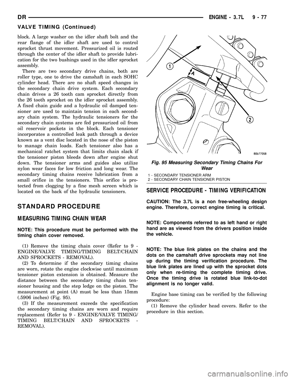
measurement at point (A) must be less than 15mm
(.5906 inches) (Fig. 95).
(3) If the measurement exceeds the specification
the secondary timing chains are worn and require
replacement (Refer to 9 - ENGINE/VALVE TIMING/
TIMING BELT/CHAIN AND SPROCKETS -
REMOVAL).
SERVICE PROCEDURE - TIMING VERIFICATION
CAUTION: The 3.7L is a non free-wheeling design
engine. Therefore, correct engine timing is critical.
NOTE: Components referred to as left hand or right
hand are as viewed from the drivers position inside
the vehicle.
NOTE: The blue link plates on the chains and the
dots on the camshaft drive sprockets may not line
up during the timing verification procedure. The
blue link plates are lined up with the sprocket dots
only when re-timing the complete timing drive.
Once the timing drive is rotated blue link-to-dot
alignment is no longer valid.
Engine base timing can be verified by the following
procedure:
(1) Remove the cylinder head covers. Refer to the
procedure in this section.
Fig. 95 Measuring Secondary Timing Chains For
Wear
1 - SECONDARY TENSIONER ARM
2 - SECONDARY CHAIN TENSIONER PISTON
DRENGINE - 3.7L 9 - 77
VALVE TIMING (Continued)
Page 1301 of 2627
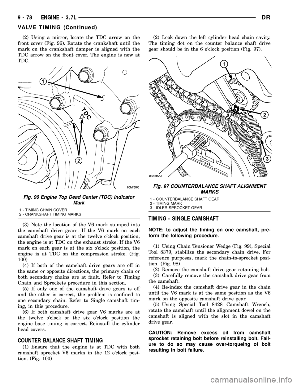
(2) Using a mirror, locate the TDC arrow on the
front cover (Fig. 96). Rotate the crankshaft until the
mark on the crankshaft damper is aligned with the
TDC arrow on the front cover. The engine is now at
TDC.
(3) Note the location of the V6 mark stamped into
the camshaft drive gears. If the V6 mark on each
camshaft drive gear is at the twelve o'clock position,
the engine is at TDC on the exhaust stroke. If the V6
mark on each gear is at the six o'clock position, the
engine is at TDC on the compression stroke. (Fig.
100)
(4) If both of the camshaft drive gears are off in
the same or opposite directions, the primary chain or
both secondary chains are at fault. Refer to Timing
Chain and Sprockets procedure in this section.
(5) If only one of the camshaft drive gears is off
and the other is correct, the problem is confined to
one secondary chain. Refer to Single camshaft tim-
ing, in this procedure.
(6) If both camshaft drive gear V6 marks are at
the twelve o'clock or the six o'clock position the
engine base timing is correct. Reinstall the cylinder
head covers.
COUNTER BALANCE SHAFT TIMING
(1) Ensure that the engine is at TDC with both
camshaft sprocket V6 marks in the 12 o'clock posi-
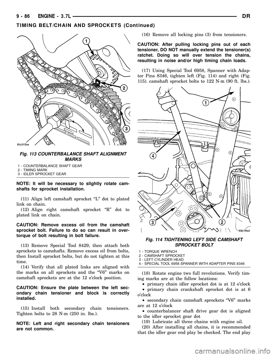
tion. (Fig. 100)(2) Look down the left cylinder head chain cavity.
The timing dot on the counter balance shaft drive
gear should be in the 6 o'clock position (Fig. 97).
TIMING - SINGLE CAMSHAFT
NOTE: to adjust the timing on one camshaft, pre-
form the following procedure.
(1) Using Chain Tensioner Wedge (Fig. 99), Special
Tool 8379, stabilize the secondary chain drive. For
reference purposes, mark the chain-to-sprocket posi-
tion. (Fig. 98)
(2) Remove the camshaft drive gear retaining bolt.
(3) Carefully remove the camshaft drive gear from
the camshaft.
(4) Re-index the camshaft drive gear in the chain
until the V6 mark is at the same position as the V6
mark on the opposite camshaft drive gear.
(5) Using Special Tool 8428 Camshaft Wrench,
rotate the camshaft until the alignment dowel on the
camshaft is aligned with the slot in the camshaft
drive gear.
CAUTION: Remove excess oil from camshaft
sprocket retaining bolt before reinstalling bolt. Fail-
ure to do so may cause over-torqueing of bolt
resulting in bolt failure.
Fig. 96 Engine Top Dead Center (TDC) Indicator
Mark
1 - TIMING CHAIN COVER
2 - CRANKSHAFT TIMING MARKS
Fig. 97 COUNTERBALANCE SHAFT ALIGNMENT
MARKS
1 - COUNTERBALANCE SHAFT GEAR
2 - TIMING MARK
3 - IDLER SPROCKET GEAR
9 - 78 ENGINE - 3.7LDR
VALVE TIMING (Continued)
Page 1304 of 2627
IDLER SHAFT
REMOVAL
(1) Remove the primary and secondary timing
chains and sprockets. Refer to procedure in this sec-
tion.
NOTE: To remove the idler shaft, it is necessary to
tap threads into the shaft, to install the removal
tool.
(2) Using a 12 mm X 1.75 tap, cut threads in the
idler shaft center bore.
(3) Cover the radiator core with a suitable cover.
CAUTION: Use care when removing the idler shaft,
Do not strike the radiator cooling fins with the slide
hammer.
(4) Using Special Tool 8517 Slide Hammer, remove
the idler shaft.
INSTALLATION
(1) Thoroughly clean the idler shaft bore.
(2) Position the idler shaft in the bore.
NOTE: The two lubrication holes in the idler shaft
do not require any special alignment.
NOTE: Before using the retaining bolt to install the
idler shaft, coat the threads and the pilot on the
idler shaft, with clean engine oil.
(3) Using the primary idler sprocket retaining bolt
and washer, carefully draw the idler shaft into the
bore until fully seated.
(4) Coat the idler shaft with clean engine oil.
(5) Install the timing chains and sprockets. Refer
to procedure in this section.
TIMING BELT / CHAIN
COVER(S)
REMOVAL
(1) Disconnect the battery negative cable.
(2) Drain cooling system (Refer to 7 - COOLING -
STANDARD PROCEDURE).
(3) Remove electric cooling fan and fan shroud
assembly.
(4) Remove fan and fan drive assembly (Refer to 7
- COOLING/ENGINE/FAN DRIVE VISCOUS
CLUTCH - REMOVAL).
(5) Disconnect both heater hoses at timing cover.
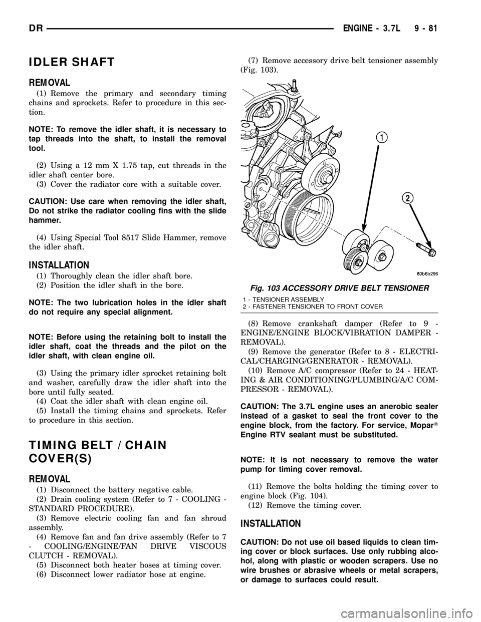
(6) Disconnect lower radiator hose at engine.(7) Remove accessory drive belt tensioner assembly
(Fig. 103).
(8) Remove crankshaft damper (Refer to 9 -
ENGINE/ENGINE BLOCK/VIBRATION DAMPER -
REMOVAL).
(9) Remove the generator (Refer to 8 - ELECTRI-
CAL/CHARGING/GENERATOR - REMOVAL).
(10) Remove A/C compressor (Refer to 24 - HEAT-
ING & AIR CONDITIONING/PLUMBING/A/C COM-
PRESSOR - REMOVAL).
CAUTION: The 3.7L engine uses an anerobic sealer
instead of a gasket to seal the front cover to the
engine block, from the factory. For service, MoparT
Engine RTV sealant must be substituted.
NOTE: It is not necessary to remove the water
pump for timing cover removal.
(11) Remove the bolts holding the timing cover to
engine block (Fig. 104).
(12) Remove the timing cover.
INSTALLATION
CAUTION: Do not use oil based liquids to clean tim-
ing cover or block surfaces. Use only rubbing alco-
hol, along with plastic or wooden scrapers. Use no
wire brushes or abrasive wheels or metal scrapers,
or damage to surfaces could result.
Fig. 103 ACCESSORY DRIVE BELT TENSIONER
1 - TENSIONER ASSEMBLY
2 - FASTENER TENSIONER TO FRONT COVER
DRENGINE - 3.7L 9 - 81
Page 1309 of 2627
NOTE: It will be necessary to slightly rotate cam-
shafts for sprocket installation.
(11) Align left camshaft sprocket ªLº dot to plated
link on chain.
(12) Align right camshaft sprocket ªRº dot to
plated link on chain.
CAUTION: Remove excess oil from the camshaft
sprocket bolt. Failure to do so can result in over-
torque of bolt resulting in bolt failure.
(13) Remove Special Tool 8429, then attach both
sprockets to camshafts. Remove excess oil from bolts,
then Install sprocket bolts, but do not tighten at this
time.
(14) Verify that all plated links are aligned with
the marks on all sprockets and the ªV6º marks on
camshaft sprockets are at the 12 o'clock position.
CAUTION: Ensure the plate between the left sec-
ondary chain tensioner and block is correctly
installed.
(15) Install both secondary chain tensioners.
Tighten bolts to 28 N´m (250 in. lbs.).
NOTE: Left and right secondary chain tensioners
are not common.(16) Remove all locking pins (3) from tensioners.
CAUTION: After pulling locking pins out of each
tensioner, DO NOT manually extend the tensioner(s)
ratchet. Doing so will over tension the chains,
resulting in noise and/or high timing chain loads.
(17) Using Special Tool 6958, Spanner with Adap-
tor Pins 8346, tighten left (Fig. 114) and right (Fig.
115). camshaft sprocket bolts to 122 N´m (90 ft. lbs.).
(18) Rotate engine two full revolutions. Verify tim-
ing marks are at the follow locations:
²primary chain idler sprocket dot is at 12 o'clock
²primary chain crankshaft sprocket dot is at 6
o'clock
²secondary chain camshaft sprockets ªV6º marks
are at 12 o'clock
²counterbalancer shaft drive gear dot is aligned
to the idler sprocket gear dot
(19) Lubricate all three chains with engine oil.
(20) After installing all chains, it is recommended
that the idler gear end play be checked. The end play
Fig. 113 COUNTERBALANCE SHAFT ALIGNMENT
MARKS
1 - COUNTERBALANCE SHAFT GEAR
2 - TIMING MARK
3 - IDLER SPROCKET GEAR
Fig. 114 TIGHTENING LEFT SIDE CAMSHAFT
SPROCKET BOLT
1 - TORQUE WRENCH
2 - CAMSHAFT SPROCKET
3 - LEFT CYLINDER HEAD
4 - SPECIAL TOOL 6958 SPANNER WITH ADAPTER PINS 8346
9 - 86 ENGINE - 3.7LDR
TIMING BELT/CHAIN AND SPROCKETS (Continued)
Page 1340 of 2627
(5) Torque the camshaft bearing cap retaining
bolts to 11 N´m (100 in. lbs.).
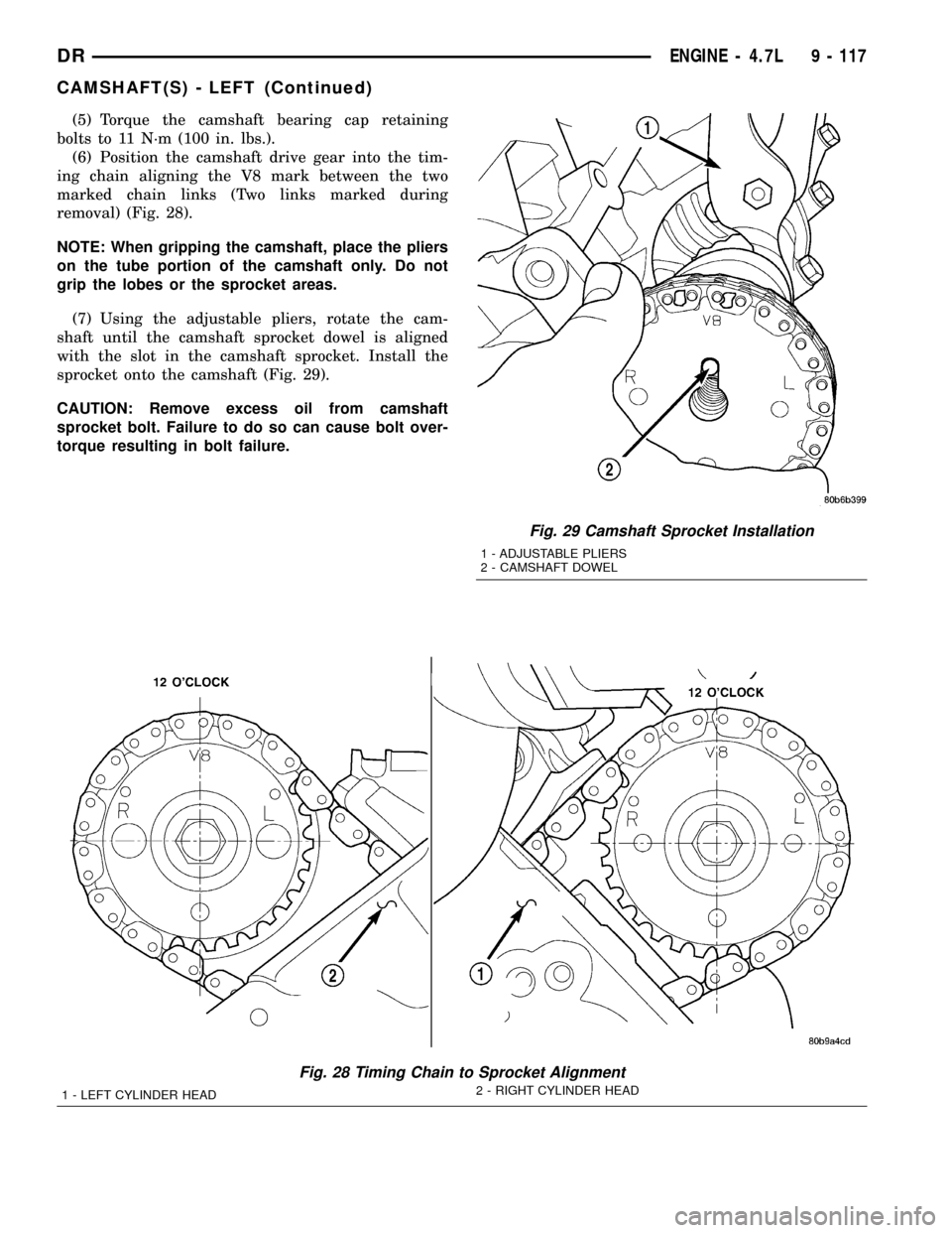
(6) Position the camshaft drive gear into the tim-
ing chain aligning the V8 mark between the two
marked chain links (Two links marked during
removal) (Fig. 28).
NOTE: When gripping the camshaft, place the pliers
on the tube portion of the camshaft only. Do not
grip the lobes or the sprocket areas.
(7) Using the adjustable pliers, rotate the cam-
shaft until the camshaft sprocket dowel is aligned
with the slot in the camshaft sprocket. Install the
sprocket onto the camshaft (Fig. 29).
CAUTION: Remove excess oil from camshaft
sprocket bolt. Failure to do so can cause bolt over-
torque resulting in bolt failure.
Fig. 28 Timing Chain to Sprocket Alignment
1 - LEFT CYLINDER HEAD2 - RIGHT CYLINDER HEAD
Fig. 29 Camshaft Sprocket Installation
1 - ADJUSTABLE PLIERS
2 - CAMSHAFT DOWEL
DRENGINE - 4.7L 9 - 117
CAMSHAFT(S) - LEFT (Continued)
Page 1344 of 2627
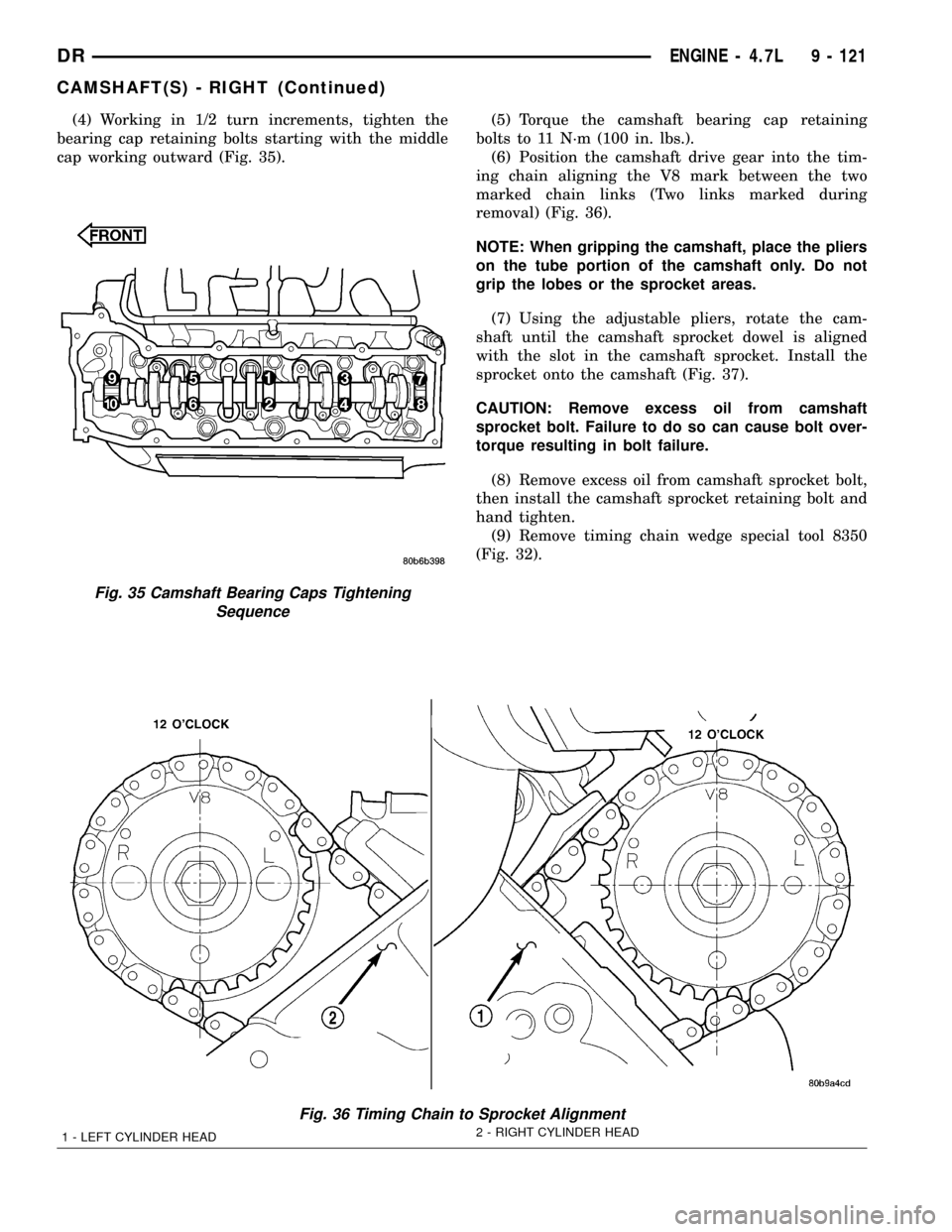
(4) Working in 1/2 turn increments, tighten the
bearing cap retaining bolts starting with the middle
cap working outward (Fig. 35).(5) Torque the camshaft bearing cap retaining
bolts to 11 N´m (100 in. lbs.).
(6) Position the camshaft drive gear into the tim-
ing chain aligning the V8 mark between the two
marked chain links (Two links marked during
removal) (Fig. 36).
NOTE: When gripping the camshaft, place the pliers
on the tube portion of the camshaft only. Do not
grip the lobes or the sprocket areas.
(7) Using the adjustable pliers, rotate the cam-
shaft until the camshaft sprocket dowel is aligned
with the slot in the camshaft sprocket. Install the
sprocket onto the camshaft (Fig. 37).
CAUTION: Remove excess oil from camshaft
sprocket bolt. Failure to do so can cause bolt over-
torque resulting in bolt failure.
(8) Remove excess oil from camshaft sprocket bolt,
then install the camshaft sprocket retaining bolt and
hand tighten.
(9) Remove timing chain wedge special tool 8350
(Fig. 32).
Fig. 36 Timing Chain to Sprocket Alignment
1 - LEFT CYLINDER HEAD2 - RIGHT CYLINDER HEAD
Fig. 35 Camshaft Bearing Caps Tightening
Sequence
DRENGINE - 4.7L 9 - 121
CAMSHAFT(S) - RIGHT (Continued)
Page 1352 of 2627
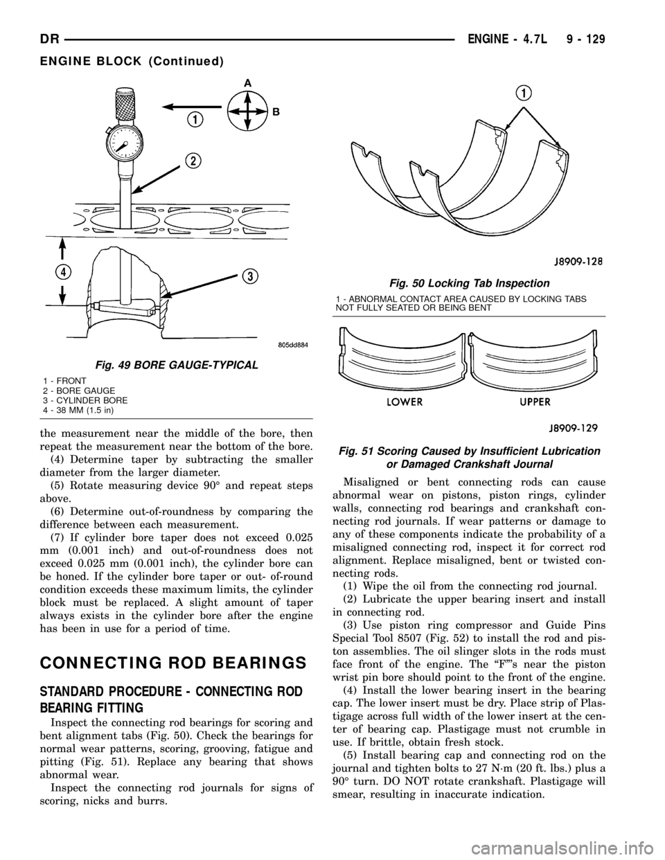
the measurement near the middle of the bore, then
repeat the measurement near the bottom of the bore.
(4) Determine taper by subtracting the smaller
diameter from the larger diameter.
(5) Rotate measuring device 90É and repeat steps
above.
(6) Determine out-of-roundness by comparing the
difference between each measurement.
(7) If cylinder bore taper does not exceed 0.025
mm (0.001 inch) and out-of-roundness does not
exceed 0.025 mm (0.001 inch), the cylinder bore can
be honed. If the cylinder bore taper or out- of-round
condition exceeds these maximum limits, the cylinder
block must be replaced. A slight amount of taper
always exists in the cylinder bore after the engine
has been in use for a period of time.
CONNECTING ROD BEARINGS
STANDARD PROCEDURE - CONNECTING ROD
BEARING FITTING
Inspect the connecting rod bearings for scoring and
bent alignment tabs (Fig. 50). Check the bearings for
normal wear patterns, scoring, grooving, fatigue and
pitting (Fig. 51). Replace any bearing that shows
abnormal wear.
Inspect the connecting rod journals for signs of
scoring, nicks and burrs.Misaligned or bent connecting rods can cause
abnormal wear on pistons, piston rings, cylinder
walls, connecting rod bearings and crankshaft con-
necting rod journals. If wear patterns or damage to
any of these components indicate the probability of a
misaligned connecting rod, inspect it for correct rod
alignment. Replace misaligned, bent or twisted con-
necting rods.
(1) Wipe the oil from the connecting rod journal.
(2) Lubricate the upper bearing insert and install
in connecting rod.
(3) Use piston ring compressor and Guide Pins
Special Tool 8507 (Fig. 52) to install the rod and pis-
ton assemblies. The oil slinger slots in the rods must
face front of the engine. The ªFº's near the piston
wrist pin bore should point to the front of the engine.
(4) Install the lower bearing insert in the bearing
cap. The lower insert must be dry. Place strip of Plas-
tigage across full width of the lower insert at the cen-
ter of bearing cap. Plastigage must not crumble in
use. If brittle, obtain fresh stock.
(5) Install bearing cap and connecting rod on the
journal and tighten bolts to 27 N´m (20 ft. lbs.) plus a
90É turn. DO NOT rotate crankshaft. Plastigage will
smear, resulting in inaccurate indication.
Fig. 49 BORE GAUGE-TYPICAL
1 - FRONT
2 - BORE GAUGE
3 - CYLINDER BORE
4 - 38 MM (1.5 in)
Fig. 50 Locking Tab Inspection
1 - ABNORMAL CONTACT AREA CAUSED BY LOCKING TABS
NOT FULLY SEATED OR BEING BENT
Fig. 51 Scoring Caused by Insufficient Lubrication
or Damaged Crankshaft Journal
DRENGINE - 4.7L 9 - 129
ENGINE BLOCK (Continued)