Alignment DODGE RAM 1500 1998 2.G Repair Manual
[x] Cancel search | Manufacturer: DODGE, Model Year: 1998, Model line: RAM 1500, Model: DODGE RAM 1500 1998 2.GPages: 2627
Page 336 of 2627
ACCESSORY DRIVE
TABLE OF CONTENTS
page page
BELT TENSIONER - 3.7L / 4.7L
DESCRIPTION.........................21
OPERATION...........................21
REMOVAL.............................21
INSTALLATION.........................22
BELT TENSIONER-5.7L
DESCRIPTION.........................22
OPERATION...........................22
REMOVAL.............................22
INSTALLATION.........................23
BELT TENSIONER - 5.9L DIESEL
DESCRIPTION.........................23
OPERATION...........................23REMOVAL.............................23
INSTALLATION.........................24
DRIVE BELT - 3.7L / 4.7L
DIAGNOSIS AND TESTING - ACCESSORY
DRIVE BELT.........................24
REMOVAL.............................26
INSTALLATION.........................26
DRIVE BELT - 5.9L DIESEL
DIAGNOSIS AND TESTINGÐACCESSORY
DRIVE BELT.........................27
REMOVAL.............................29
INSTALLATION.........................29
BELT TENSIONER - 3.7L / 4.7L
DESCRIPTION
Correct drive belt tension is required to ensure
optimum performance of the belt driven engine acces-
sories. If specified tension is not maintained, belt
slippage may cause; engine overheating, lack of
power steering assist, loss of air conditioning capac-
ity, reduced generator output rate, and greatly
reduced belt life.
It is not necessary to adjust belt tension on the
3.7L or 4.7L engine. These engines are equipped with
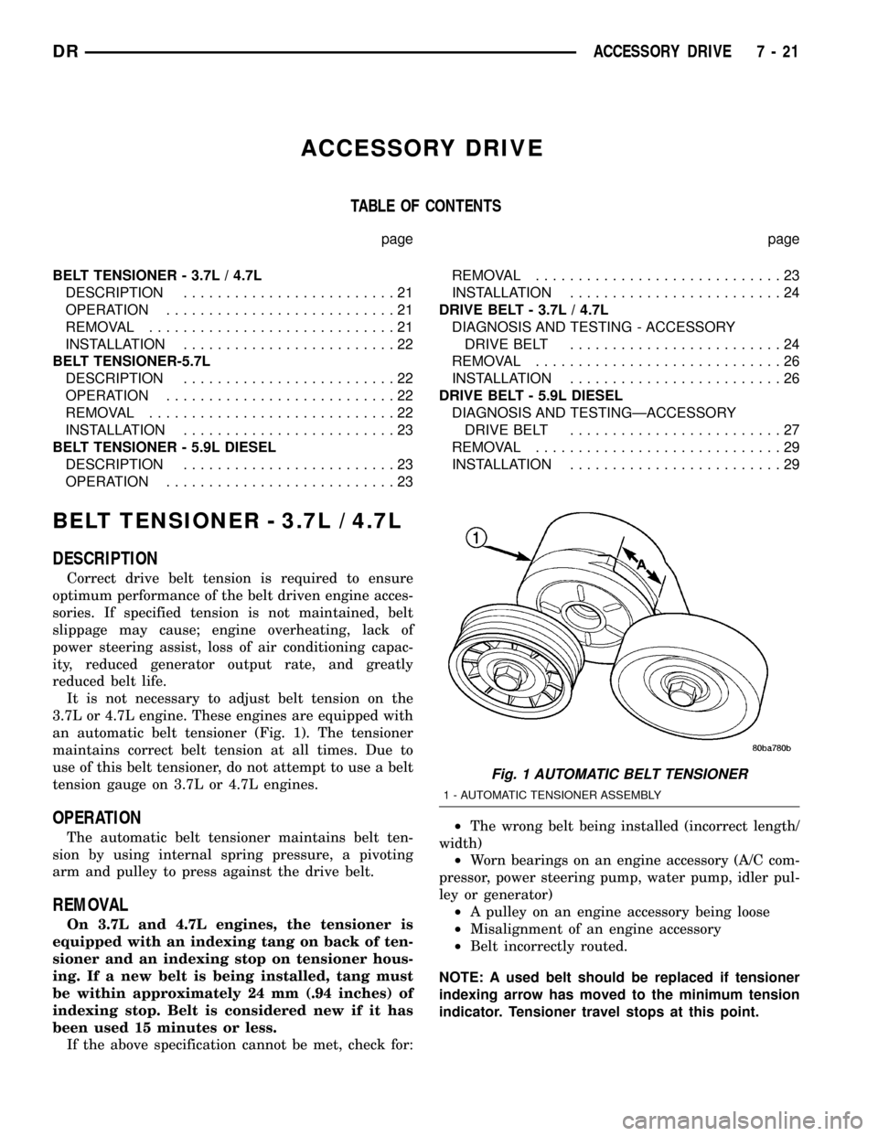
an automatic belt tensioner (Fig. 1). The tensioner
maintains correct belt tension at all times. Due to
use of this belt tensioner, do not attempt to use a belt
tension gauge on 3.7L or 4.7L engines.
OPERATION
The automatic belt tensioner maintains belt ten-
sion by using internal spring pressure, a pivoting
arm and pulley to press against the drive belt.
REMOVAL
On 3.7L and 4.7L engines, the tensioner is
equipped with an indexing tang on back of ten-
sioner and an indexing stop on tensioner hous-
ing. If a new belt is being installed, tang must
be within approximately 24 mm (.94 inches) of
indexing stop. Belt is considered new if it has
been used 15 minutes or less.
If the above specification cannot be met, check for:²The wrong belt being installed (incorrect length/
width)
²Worn bearings on an engine accessory (A/C com-
pressor, power steering pump, water pump, idler pul-
ley or generator)
²A pulley on an engine accessory being loose
²Misalignment of an engine accessory
²Belt incorrectly routed.
NOTE: A used belt should be replaced if tensioner
indexing arrow has moved to the minimum tension
indicator. Tensioner travel stops at this point.
Fig. 1 AUTOMATIC BELT TENSIONER
1 - AUTOMATIC TENSIONER ASSEMBLY
DRACCESSORY DRIVE 7 - 21
Page 339 of 2627
INSTALLATION
(1) Install tensioner assembly to water inlet
bracket. A dowel is located on back of tensioner. Align
this dowel to hole in tensioner mounting bracket.
Tighten bolt to 43 N´m (32 ft. lbs.) torque.
(2) Install drive belt (Refer to 7 - COOLING/AC-
CESSORY DRIVE/DRIVE BELTS - INSTALLA-
TION).
DRIVE BELT - 3.7L / 4.7L
DIAGNOSIS AND TESTING - ACCESSORY
DRIVE BELT
VISUAL DIAGNOSIS
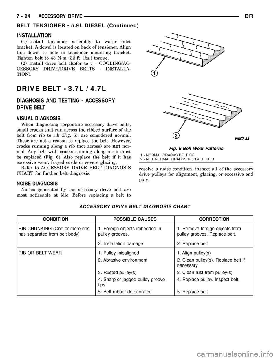
When diagnosing serpentine accessory drive belts,
small cracks that run across the ribbed surface of the
belt from rib to rib (Fig. 6), are considered normal.
These are not a reason to replace the belt. However,
cracks running along a rib (not across) arenotnor-
mal. Any belt with cracks running along a rib must
be replaced (Fig. 6). Also replace the belt if it has
excessive wear, frayed cords or severe glazing.
Refer to ACCESSORY DRIVE BELT DIAGNOSIS
CHART for further belt diagnosis.
NOISE DIAGNOSIS
Noises generated by the accessory drive belt are
most noticeable at idle. Before replacing a belt toresolve a noise condition, inspect all of the accessory
drive pulleys for alignment, glazing, or excessive end
play.
ACCESSORY DRIVE BELT DIAGNOSIS CHART
CONDITION POSSIBLE CAUSES CORRECTION
RIB CHUNKING (One or more ribs
has separated from belt body)1. Foreign objects imbedded in
pulley grooves.1. Remove foreign objects from
pulley grooves. Replace belt.
2. Installation damage 2. Replace belt
RIB OR BELT WEAR 1. Pulley misaligned 1. Align pulley(s)
2. Abrasive environment 2. Clean pulley(s). Replace belt if
necessary
3. Rusted pulley(s) 3. Clean rust from pulley(s)
4. Sharp or jagged pulley groove
tips4. Replace pulley. Inspect belt.
5. Belt rubber deteriorated 5. Replace belt
Fig. 6 Belt Wear Patterns
1 - NORMAL CRACKS BELT OK
2 - NOT NORMAL CRACKS REPLACE BELT
7 - 24 ACCESSORY DRIVEDR
BELT TENSIONER - 5.9L DIESEL (Continued)
Page 340 of 2627
CONDITION POSSIBLE CAUSES CORRECTION
BELT SLIPS 1. Belt slipping because of
insufficient tension1. Inspect/Replace tensioner if
necessary
2. Belt or pulley exposed to
substance that has reduced friction
(belt dressing, oil, ethylene glycol)2. Replace belt and clean pulleys
3. Driven component bearing failure
(seizure)3. Replace faulty component or
bearing
4. Belt glazed or hardened from
heat and excessive slippage4. Replace belt.
LONGITUDAL BELT CRACKING 1. Belt has mistracked from pulley
groove1. Replace belt
2. Pulley groove tip has worn away
rubber to tensile member2. Replace belt
9GROOVE JUMPING9
(Belt does not maintain correct
position on pulley)1. Incorrect belt tension 1. Inspect/Replace tensioner if
necessary
2. Pulley(s) not within design
tolerance2. Replace pulley(s)
3. Foreign object(s) in grooves 3. Remove foreign objects from
grooves
4. Pulley misalignment 4. Align component
5. Belt cordline is broken 5. Replace belt
BELT BROKEN
(Note: Identify and correct problem
before new belt is installed)1. Incorrect belt tension 1. Replace Inspect/Replace
tensioner if necessary
2. Tensile member damaged during
belt installation2. Replace belt
3. Severe misalignment 3. Align pulley(s)
4. Bracket, pulley, or bearing failure 4. Replace defective component
and belt
NOISE
(Objectionable squeal, squeak, or
rumble is heard or felt while drive
belt is in operation)1. Incorrect belt tension 1. Inspect/Replace tensioner if
necessary
2. Bearing noise 2. Locate and repair
3. Belt misalignment 3. Align belt/pulley(s)
4. Belt to pulley mismatch 4. Install correct belt
5. Driven component induced
vibration5. Locate defective driven
component and repair
TENSION SHEETING FABRIC
FAILURE
(Woven fabric on outside,
circumference of belt has cracked or
separated from body of belt)1. Tension sheeting contacting
stationary object1. Correct rubbing condition
2. Excessive heat causing woven
fabric to age2. Replace belt
3. Tension sheeting splice has
fractured3. Replace belt
DRACCESSORY DRIVE 7 - 25
DRIVE BELT - 3.7L / 4.7L (Continued)
Page 342 of 2627
DRIVE BELT - 5.9L DIESEL
DIAGNOSIS AND TESTINGÐACCESSORY
DRIVE BELT
VISUAL DIAGNOSIS
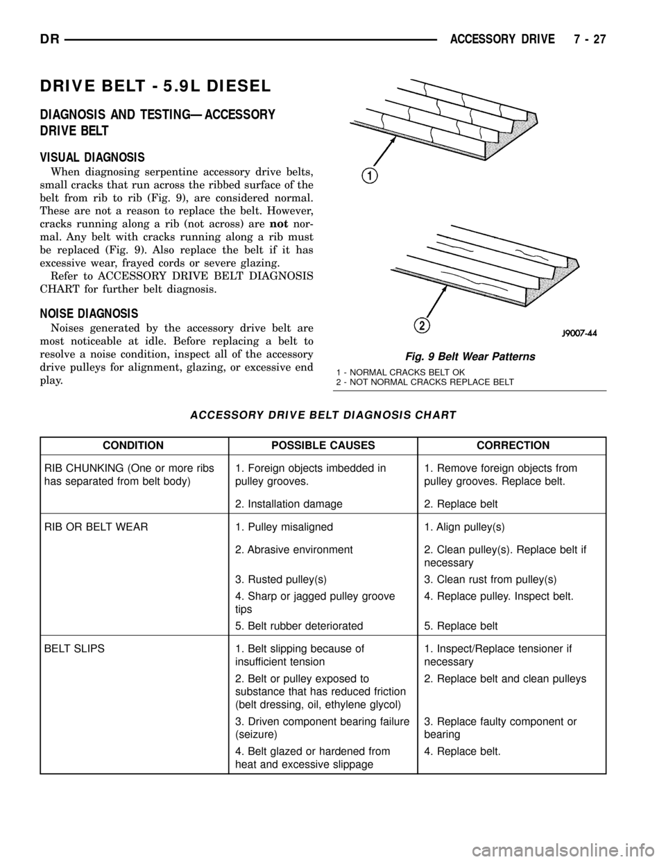
When diagnosing serpentine accessory drive belts,
small cracks that run across the ribbed surface of the
belt from rib to rib (Fig. 9), are considered normal.
These are not a reason to replace the belt. However,
cracks running along a rib (not across) arenotnor-
mal. Any belt with cracks running along a rib must
be replaced (Fig. 9). Also replace the belt if it has
excessive wear, frayed cords or severe glazing.
Refer to ACCESSORY DRIVE BELT DIAGNOSIS
CHART for further belt diagnosis.
NOISE DIAGNOSIS
Noises generated by the accessory drive belt are
most noticeable at idle. Before replacing a belt to
resolve a noise condition, inspect all of the accessory
drive pulleys for alignment, glazing, or excessive end
play.
ACCESSORY DRIVE BELT DIAGNOSIS CHART
CONDITION POSSIBLE CAUSES CORRECTION
RIB CHUNKING (One or more ribs
has separated from belt body)1. Foreign objects imbedded in
pulley grooves.1. Remove foreign objects from
pulley grooves. Replace belt.
2. Installation damage 2. Replace belt
RIB OR BELT WEAR 1. Pulley misaligned 1. Align pulley(s)
2. Abrasive environment 2. Clean pulley(s). Replace belt if
necessary
3. Rusted pulley(s) 3. Clean rust from pulley(s)
4. Sharp or jagged pulley groove
tips4. Replace pulley. Inspect belt.
5. Belt rubber deteriorated 5. Replace belt
BELT SLIPS 1. Belt slipping because of
insufficient tension1. Inspect/Replace tensioner if
necessary
2. Belt or pulley exposed to
substance that has reduced friction
(belt dressing, oil, ethylene glycol)2. Replace belt and clean pulleys
3. Driven component bearing failure
(seizure)3. Replace faulty component or
bearing
4. Belt glazed or hardened from
heat and excessive slippage4. Replace belt.
Fig. 9 Belt Wear Patterns
1 - NORMAL CRACKS BELT OK
2 - NOT NORMAL CRACKS REPLACE BELT
DRACCESSORY DRIVE 7 - 27
Page 343 of 2627
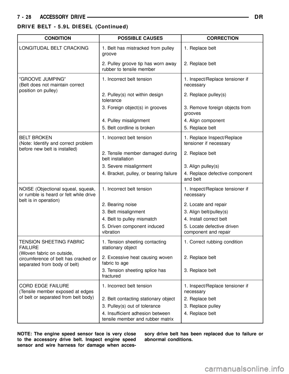
CONDITION POSSIBLE CAUSES CORRECTION
LONGITUDAL BELT CRACKING 1. Belt has mistracked from pulley
groove1. Replace belt
2. Pulley groove tip has worn away
rubber to tensile member2. Replace belt
9GROOVE JUMPING9
(Belt does not maintain correct
position on pulley)1. Incorrect belt tension 1. Inspect/Replace tensioner if
necessary
2. Pulley(s) not within design
tolerance2. Replace pulley(s)
3. Foreign object(s) in grooves 3. Remove foreign objects from
grooves
4. Pulley misalignment 4. Align component
5. Belt cordline is broken 5. Replace belt
BELT BROKEN
(Note: Identify and correct problem
before new belt is installed)1. Incorrect belt tension 1. Replace Inspect/Replace
tensioner if necessary
2. Tensile member damaged during
belt installation2. Replace belt
3. Severe misalignment 3. Align pulley(s)
4. Bracket, pulley, or bearing failure 4. Replace defective component
and belt
NOISE (Objectional squeal, squeak,
or rumble is heard or felt while drive
belt is in operation)1. Incorrect belt tension 1. Inspect/Replace tensioner if
necessary
2. Bearing noise 2. Locate and repair
3. Belt misalignment 3. Align belt/pulley(s)
4. Belt to pulley mismatch 4. Install correct belt
5. Driven component induced
vibration5. Locate defective driven
component and repair
TENSION SHEETING FABRIC
FAILURE
(Woven fabric on outside,
circumference of belt has cracked or
separated from body of belt)1. Tension sheeting contacting
stationary object1. Correct rubbing condition
2. Excessive heat causing woven
fabric to age2. Replace belt
3. Tension sheeting splice has
fractured3. Replace belt
CORD EDGE FAILURE
(Tensile member exposed at edges
of belt or separated from belt body)1. Incorrect belt tension 1. Inspect/Replace tensioner if
necessary
2. Belt contacting stationary object 2. Replace belt
3. Pulley(s) out of tolerance 3. Replace pulley
4. Insufficient adhesion between
tensile member and rubber matrix4. Replace belt
NOTE: The engine speed sensor face is very close
to the accessory drive belt. Inspect engine speed
sensor and wire harness for damage when acces-sory drive belt has been replaced due to failure or
abnormal conditions.
7 - 28 ACCESSORY DRIVEDR
DRIVE BELT - 5.9L DIESEL (Continued)
Page 370 of 2627
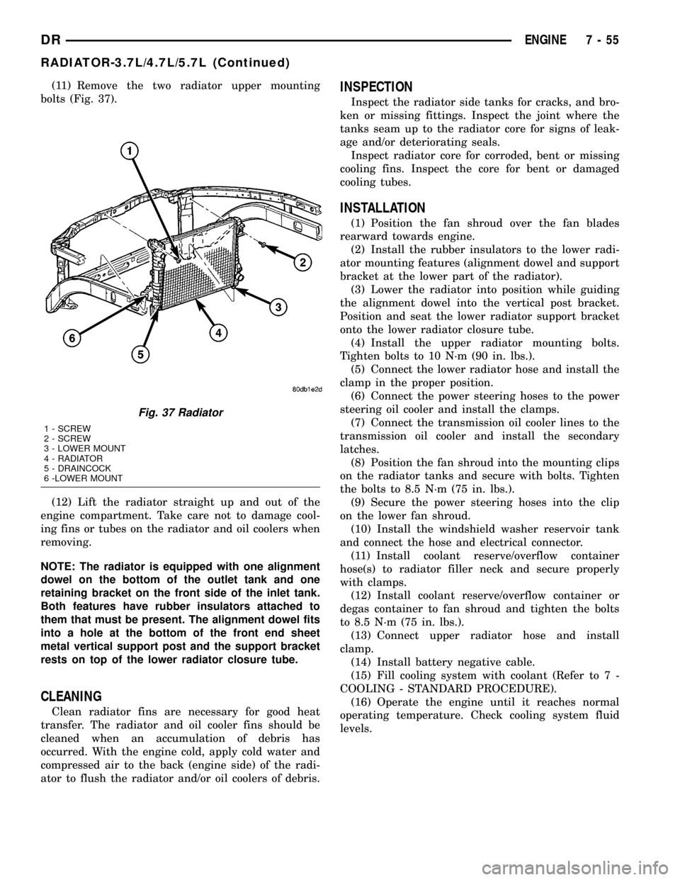
(11) Remove the two radiator upper mounting
bolts (Fig. 37).
(12) Lift the radiator straight up and out of the
engine compartment. Take care not to damage cool-
ing fins or tubes on the radiator and oil coolers when
removing.
NOTE: The radiator is equipped with one alignment
dowel on the bottom of the outlet tank and one
retaining bracket on the front side of the inlet tank.
Both features have rubber insulators attached to
them that must be present. The alignment dowel fits
into a hole at the bottom of the front end sheet
metal vertical support post and the support bracket
rests on top of the lower radiator closure tube.
CLEANING
Clean radiator fins are necessary for good heat
transfer. The radiator and oil cooler fins should be
cleaned when an accumulation of debris has
occurred. With the engine cold, apply cold water and
compressed air to the back (engine side) of the radi-
ator to flush the radiator and/or oil coolers of debris.
INSPECTION
Inspect the radiator side tanks for cracks, and bro-
ken or missing fittings. Inspect the joint where the
tanks seam up to the radiator core for signs of leak-
age and/or deteriorating seals.
Inspect radiator core for corroded, bent or missing
cooling fins. Inspect the core for bent or damaged
cooling tubes.
INSTALLATION
(1) Position the fan shroud over the fan blades
rearward towards engine.
(2) Install the rubber insulators to the lower radi-
ator mounting features (alignment dowel and support
bracket at the lower part of the radiator).
(3) Lower the radiator into position while guiding
the alignment dowel into the vertical post bracket.
Position and seat the lower radiator support bracket
onto the lower radiator closure tube.
(4) Install the upper radiator mounting bolts.
Tighten bolts to 10 N´m (90 in. lbs.).
(5) Connect the lower radiator hose and install the
clamp in the proper position.
(6) Connect the power steering hoses to the power
steering oil cooler and install the clamps.
(7) Connect the transmission oil cooler lines to the
transmission oil cooler and install the secondary
latches.
(8) Position the fan shroud into the mounting clips
on the radiator tanks and secure with bolts. Tighten
the bolts to 8.5 N´m (75 in. lbs.).
(9) Secure the power steering hoses into the clip
on the lower fan shroud.
(10) Install the windshield washer reservoir tank
and connect the hose and electrical connector.
(11) Install coolant reserve/overflow container
hose(s) to radiator filler neck and secure properly
with clamps.
(12) Install coolant reserve/overflow container or
degas container to fan shroud and tighten the bolts
to 8.5 N´m (75 in. lbs.).
(13) Connect upper radiator hose and install
clamp.
(14) Install battery negative cable.
(15) Fill cooling system with coolant (Refer to 7 -
COOLING - STANDARD PROCEDURE).
(16) Operate the engine until it reaches normal
operating temperature. Check cooling system fluid
levels.
Fig. 37 Radiator
1 - SCREW
2 - SCREW
3 - LOWER MOUNT
4 - RADIATOR
5 - DRAINCOCK
6 -LOWER MOUNT
DRENGINE 7 - 55
RADIATOR-3.7L/4.7L/5.7L (Continued)
Page 371 of 2627
RADIATOR - 5.9L DIESEL
DESCRIPTION
The radiator is a aluminum cross-flow design with
horizontal tubes through the radiator core and verti-
cal plastic side tanks (Fig. 38).
This radiator does not contain an internal trans-
mission oil cooler.
OPERATION
The radiator supplies sufficient heat transfer using
the cooling fins interlaced between the horizontal
tubes in the radiator core to cool the engine.
DIAGNOSIS AND TESTING - RADIATOR
COOLANT FLOW
Use the following procedure to determine if coolant
is flowing through the cooling system.
(1) Idle engine until operating temperature is
reached. If the upper radiator hose is warm to the
touch, the thermostat is opening and coolant is flow-
ing to the radiator.
WARNING: HOT, PRESSURIZED COOLANT CAN
CAUSE INJURY BY SCALDING. USING A RAG TO
COVER THE RADIATOR PRESSURE CAP, OPEN
RADIATOR CAP SLOWLY TO THE FIRST STOP. THIS
WILL ALLOW ANY BUILT-UP PRESSURE TO VENT
TO THE RESERVE/OVERFLOW TANK. AFTER PRES-
SURE BUILD-UP HAS BEEN RELEASED, REMOVE
CAP FROM FILLER NECK.
(2) Drain a small amount of coolant from the radi-
ator until the ends of the radiator tubes are visible
through the filler neck. Idle the engine at normal
operating temperature. If coolant is flowing past the
exposed tubes, the coolant is circulating.
REMOVAL
(1) Disconnect both battery negative cables.
WARNING: DO NOT REMOVE THE CYLINDER
BLOCK DRAIN PLUGS OR LOOSEN THE RADIATOR
DRAINCOCK WITH THE SYSTEM HOT AND UNDER
PRESSURE. SERIOUS BURNS FROM COOLANT
CAN OCCUR.
(2) Drain the cooling system (Refer to 7 - COOL-
ING - STANDARD PROCEDURE).
WARNING: CONSTANT TENSION HOSE CLAMPS
ARE USED ON MOST COOLING SYSTEM HOSES.
WHEN REMOVING OR INSTALLING, USE ONLY
TOOLS DESIGNED FOR SERVICING THIS TYPE OF
CLAMP, SUCH AS SPECIAL CLAMP TOOL (NUMBER6094). ALWAYS WEAR SAFETY GLASSES WHEN
SERVICING CONSTANT TENSION CLAMPS.
CAUTION: A number or letter is stamped into the
tongue of constant tension clamps. If replacement
is necessary, use only an original equipment clamp
with a matching number or letter.
(3) Remove air box and turbocharger inlet tube.
(4) Remove coolant tank hose, washer bottle hose
and the positive battery cable from the fastening
clips located on top of the radiator.
(5) Remove hose clamps and hoses from radiator.
(6) Remove the power steering cooler mounting
bolts and position the power steering cooler out of
the way.
(7) Disconnect the transmission cooler lines at the
transmission cooler. The transmission cooler will
remain on the radiator and can be removed as an
assembly.
(8) Disconnect the electronic viscous fan drive elec-
trical connector.
(9) Using a fastener removal tool, remove the two
push pins and the lower shroud assembly and elec-
tronic viscous fan drive wiring from the upper shroud
assembly. Position wiring out of the way. Do not
impact or damage the electronic viscous fan drive or
pull it's wiring.
(10) Using a fastener tool, remove the wiring har-
ness bracket from the upper fan shroud.
(11) Remove the two radiator upper mounting
bolts (Fig. 38).
(12) Lift radiator straight up and out of engine
compartment. The bottom of the radiator is equipped
with two alignment dowels that fit into holes in the
lower radiator support panel. Rubber biscuits (insu-
lators) are installed to these dowels. Take care not to
damage cooling fins or tubes on the radiator and air
conditioning condenser or the electronic viscous fan
connector when removing.
CLEANING
Clean radiator fins are necessary for good heat
transfer. The radiator and oil cooler fins should be
cleaned when an accumulation of debris has
occurred. With the engine cold, apply cold water and
compressed air to the back (engine side) of the radi-
ator to flush the radiator and/or oil coolers of debris.
INSPECTION
Inspect the radiator side tanks for cracks, and bro-
ken or missing fittings. Inspect the joint where the
tanks seam up to the radiator core for signs of leak-
age and/or deteriorating seals.
Inspect radiator core for corroded, bent or missing
cooling fins. Inspect the core for bent or damaged
cooling tubes.
7 - 56 ENGINEDR
Page 372 of 2627
INSTALLATION
(1) Install rubber insulators to alignment dowels
at lower part of radiator.
(2) Lower the radiator into position while guiding
the two alignment dowels into lower radiator sup-
port. Different alignment holes are provided in the
lower radiator support for each engine application.
(3) Install two upper radiator mounting bolts.
Tighten bolts to 11.8 N´m (105 in. lbs.) torque.
(4) Connect both radiator hoses and install hose
clamps.
(5) Connect transmission cooler lines to transmis-
sion cooler. Inspect quick connect fittings for debris
and install until an audible ªclickº is heard. Pull
apart to verify connection.
(6) Position power steering cooler on the radiator
and tighten nuts to 10 N´m (90 in. lbs.)
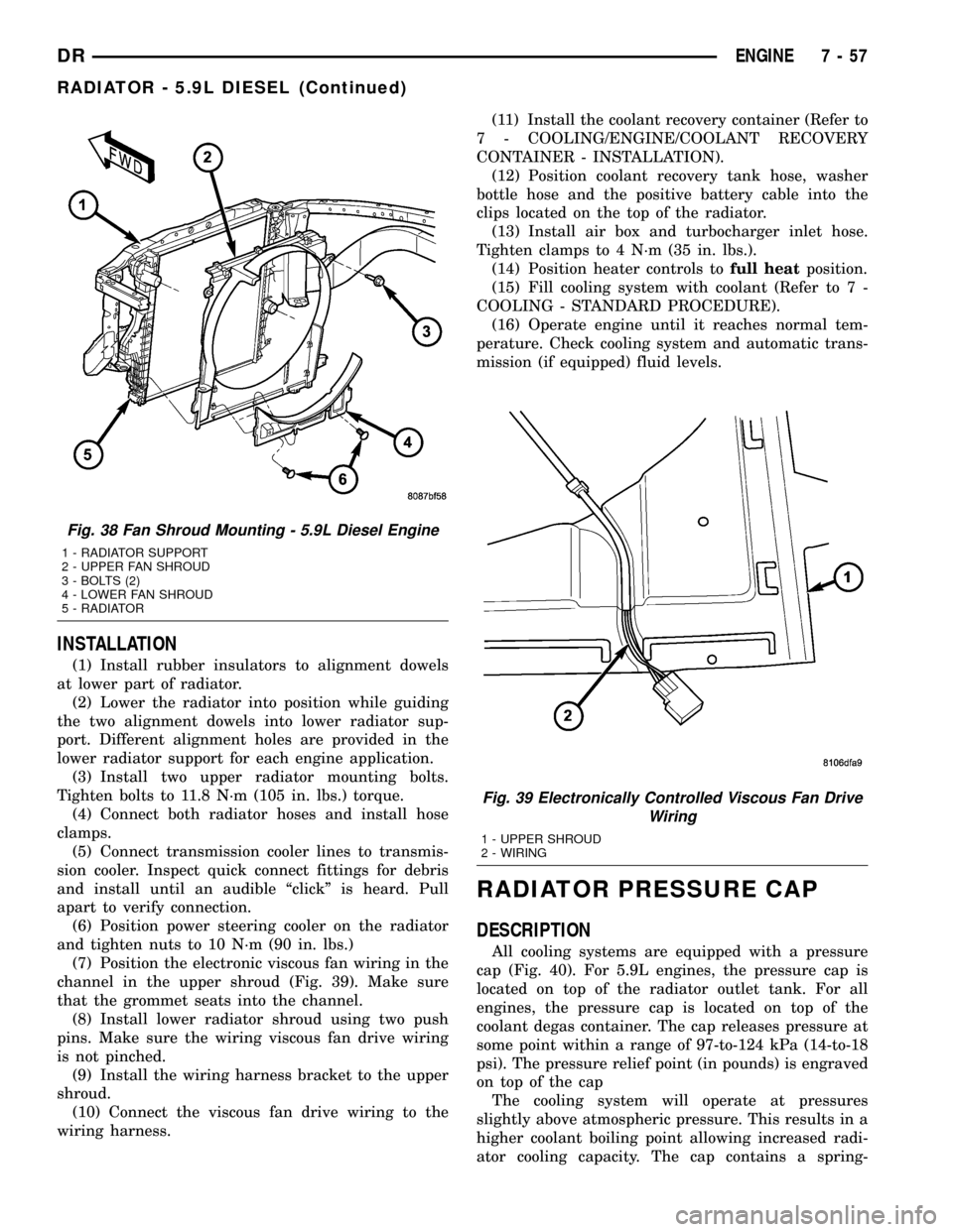
(7) Position the electronic viscous fan wiring in the
channel in the upper shroud (Fig. 39). Make sure
that the grommet seats into the channel.
(8) Install lower radiator shroud using two push
pins. Make sure the wiring viscous fan drive wiring
is not pinched.
(9) Install the wiring harness bracket to the upper
shroud.
(10) Connect the viscous fan drive wiring to the
wiring harness.(11) Install the coolant recovery container (Refer to
7 - COOLING/ENGINE/COOLANT RECOVERY
CONTAINER - INSTALLATION).
(12) Position coolant recovery tank hose, washer
bottle hose and the positive battery cable into the
clips located on the top of the radiator.
(13) Install air box and turbocharger inlet hose.
Tighten clamps to 4 N´m (35 in. lbs.).
(14) Position heater controls tofull heatposition.
(15) Fill cooling system with coolant (Refer to 7 -
COOLING - STANDARD PROCEDURE).
(16) Operate engine until it reaches normal tem-
perature. Check cooling system and automatic trans-
mission (if equipped) fluid levels.
RADIATOR PRESSURE CAP
DESCRIPTION
All cooling systems are equipped with a pressure
cap (Fig. 40). For 5.9L engines, the pressure cap is
located on top of the radiator outlet tank. For all
engines, the pressure cap is located on top of the
coolant degas container. The cap releases pressure at
some point within a range of 97-to-124 kPa (14-to-18
psi). The pressure relief point (in pounds) is engraved
on top of the cap
The cooling system will operate at pressures
slightly above atmospheric pressure. This results in a
higher coolant boiling point allowing increased radi-
ator cooling capacity. The cap contains a spring-
Fig. 38 Fan Shroud Mounting - 5.9L Diesel Engine
1 - RADIATOR SUPPORT
2 - UPPER FAN SHROUD
3 - BOLTS (2)
4 - LOWER FAN SHROUD
5 - RADIATOR
Fig. 39 Electronically Controlled Viscous Fan Drive
Wiring
1 - UPPER SHROUD
2 - WIRING
DRENGINE 7 - 57
RADIATOR - 5.9L DIESEL (Continued)
Page 571 of 2627
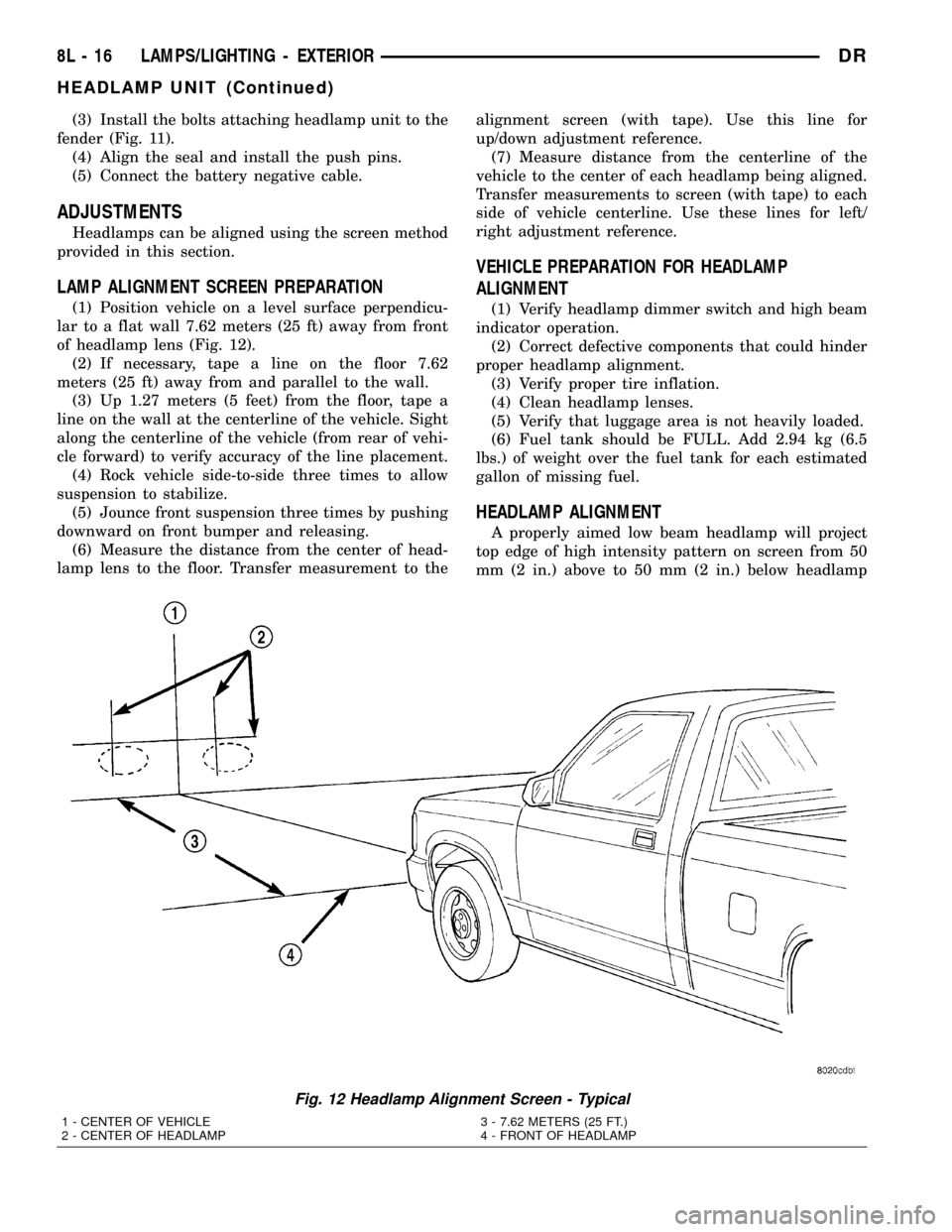
(3) Install the bolts attaching headlamp unit to the
fender (Fig. 11).
(4) Align the seal and install the push pins.
(5) Connect the battery negative cable.
ADJUSTMENTS
Headlamps can be aligned using the screen method
provided in this section.
LAMP ALIGNMENT SCREEN PREPARATION
(1) Position vehicle on a level surface perpendicu-
lar to a flat wall 7.62 meters (25 ft) away from front
of headlamp lens (Fig. 12).
(2) If necessary, tape a line on the floor 7.62
meters (25 ft) away from and parallel to the wall.
(3) Up 1.27 meters (5 feet) from the floor, tape a
line on the wall at the centerline of the vehicle. Sight
along the centerline of the vehicle (from rear of vehi-
cle forward) to verify accuracy of the line placement.
(4) Rock vehicle side-to-side three times to allow
suspension to stabilize.
(5) Jounce front suspension three times by pushing
downward on front bumper and releasing.
(6) Measure the distance from the center of head-
lamp lens to the floor. Transfer measurement to thealignment screen (with tape). Use this line for
up/down adjustment reference.
(7) Measure distance from the centerline of the
vehicle to the center of each headlamp being aligned.
Transfer measurements to screen (with tape) to each
side of vehicle centerline. Use these lines for left/
right adjustment reference.
VEHICLE PREPARATION FOR HEADLAMP
ALIGNMENT
(1) Verify headlamp dimmer switch and high beam
indicator operation.
(2) Correct defective components that could hinder
proper headlamp alignment.
(3) Verify proper tire inflation.
(4) Clean headlamp lenses.
(5) Verify that luggage area is not heavily loaded.
(6) Fuel tank should be FULL. Add 2.94 kg (6.5
lbs.) of weight over the fuel tank for each estimated
gallon of missing fuel.
HEADLAMP ALIGNMENT
A properly aimed low beam headlamp will project
top edge of high intensity pattern on screen from 50
mm (2 in.) above to 50 mm (2 in.) below headlamp
Fig. 12 Headlamp Alignment Screen - Typical
1 - CENTER OF VEHICLE
2 - CENTER OF HEADLAMP3 - 7.62 METERS (25 FT.)
4 - FRONT OF HEADLAMP
8L - 16 LAMPS/LIGHTING - EXTERIORDR
HEADLAMP UNIT (Continued)
Page 572 of 2627
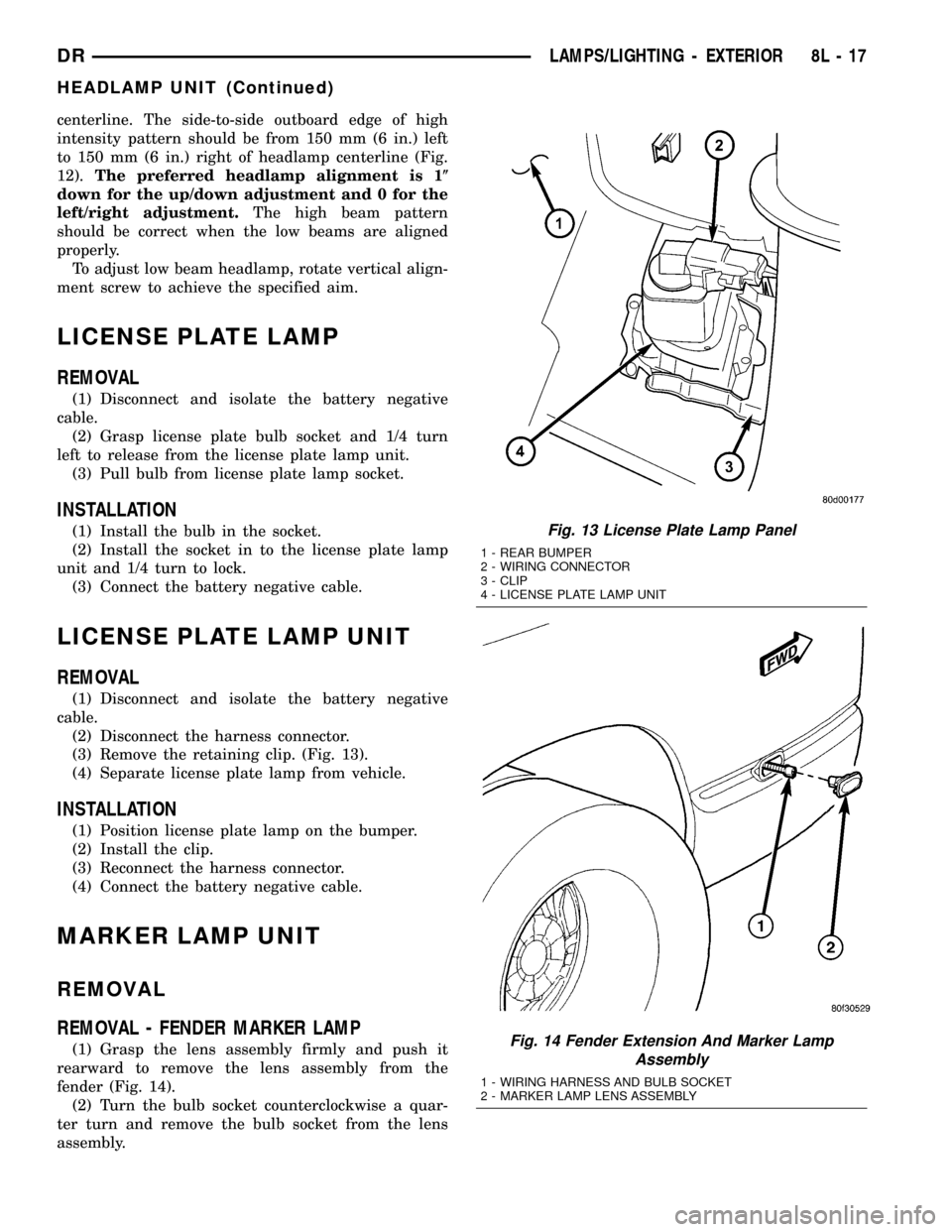
centerline. The side-to-side outboard edge of high
intensity pattern should be from 150 mm (6 in.) left
to 150 mm (6 in.) right of headlamp centerline (Fig.
12).The preferred headlamp alignment is 1(
down for the up/down adjustment and 0 for the
left/right adjustment.The high beam pattern
should be correct when the low beams are aligned
properly.
To adjust low beam headlamp, rotate vertical align-
ment screw to achieve the specified aim.
LICENSE PLATE LAMP
REMOVAL
(1) Disconnect and isolate the battery negative
cable.
(2) Grasp license plate bulb socket and 1/4 turn
left to release from the license plate lamp unit.
(3) Pull bulb from license plate lamp socket.
INSTALLATION
(1) Install the bulb in the socket.
(2) Install the socket in to the license plate lamp
unit and 1/4 turn to lock.
(3) Connect the battery negative cable.
LICENSE PLATE LAMP UNIT
REMOVAL
(1) Disconnect and isolate the battery negative
cable.
(2) Disconnect the harness connector.
(3) Remove the retaining clip. (Fig. 13).
(4) Separate license plate lamp from vehicle.
INSTALLATION
(1) Position license plate lamp on the bumper.
(2) Install the clip.
(3) Reconnect the harness connector.
(4) Connect the battery negative cable.
MARKER LAMP UNIT
REMOVAL
REMOVAL - FENDER MARKER LAMP
(1) Grasp the lens assembly firmly and push it
rearward to remove the lens assembly from the
fender (Fig. 14).
(2) Turn the bulb socket counterclockwise a quar-
ter turn and remove the bulb socket from the lens
assembly.
Fig. 13 License Plate Lamp Panel
1 - REAR BUMPER
2 - WIRING CONNECTOR
3 - CLIP
4 - LICENSE PLATE LAMP UNIT
Fig. 14 Fender Extension And Marker Lamp
Assembly
1 - WIRING HARNESS AND BULB SOCKET
2 - MARKER LAMP LENS ASSEMBLY
DRLAMPS/LIGHTING - EXTERIOR 8L - 17
HEADLAMP UNIT (Continued)