Fig DODGE RAM 1500 1998 2.G Manual PDF
[x] Cancel search | Manufacturer: DODGE, Model Year: 1998, Model line: RAM 1500, Model: DODGE RAM 1500 1998 2.GPages: 2627
Page 101 of 2627
HALF SHAFT
TABLE OF CONTENTS
page page
HALF SHAFT
CAUTION.............................20
DIAGNOSIS AND TESTING................20
REMOVAL.............................20
INSTALLATION.........................21
SPECIFICATIONS.......................21
SPECIAL TOOLS.......................21CV JOINT-OUTER
REMOVAL.............................22
INSTALLATION.........................23
CV JOINT-INNER
REMOVAL.............................25
INSTALLATION.........................25
HALF SHAFT
CAUTION
CAUTION:: Never grasp half shaft assembly by the
boots. This may cause the boot to pucker or crease
and reduce the service life of the boot.
Avoid over angulating or stroking the C/V joints
when handling the half shaft.
Half shafts exposed to battery acid, transmission
fluid, brake fluid, differential fluid or gasoline may
cause the boots to deteriorate. Failure to heed cau-
tion may result in damage.
DIAGNOSIS AND TESTING
Check inboard and outboard C/V joint for leaking
grease. This is a sign of boot or boot clamp damage.
NOISE/VIBRATION IN TURNS
A clicking noise or vibration in turns could be
caused by a damaged outer C/V or inner tripod joint
seal boot or seal boot clamps. This will result in the
loss/contamination of the joint grease, resulting in
inadequate lubrication of the joint. Noise could also
be caused by another component of the vehicle com-
ing in contact with the half shafts.
CLUNKING NOISE DURING ACCELERATION
This noise may be a damaged or worn C/V joint. A
torn boot or loose/missing clamp on the inner/outer
joint which has allowed the grease to be lost will
damage the C/V joint.
SHUDDER/VIBRATION DURING ACCELERATION
This could be a worn/damaged inner tripod joint or
a sticking tripod joint. Improper wheel alignment
may also cause a shudder or vibration.
VIBRATION AT HIGHWAY SPEEDS
This problem could be a result of out of balance
front tires or tire/wheel runout. Foreign material
(mud, etc.) packed on the backside of the wheel(s)
will also cause a vibration.
REMOVAL
(1) With vehicle in neutral, position vehicle on
hoist.
(2) Remove half shaft hub nut.
(3) Remove brake caliper and rotor.
(4) Position hydraulic jack under lower suspension
arm and raise jack to unload rebound bumper.
(5) Remove lower shock absorber bolt.
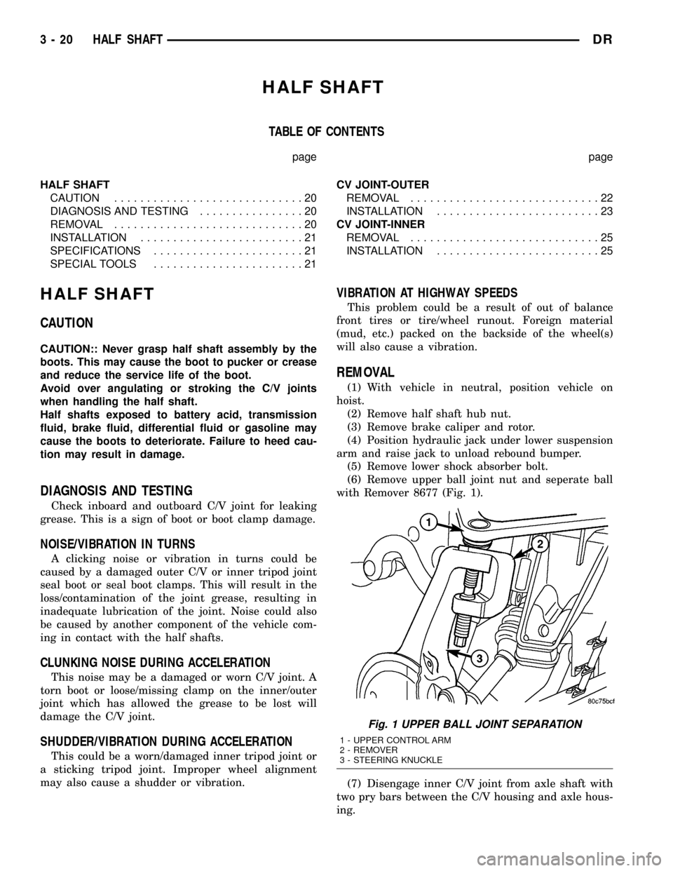
(6) Remove upper ball joint nut and seperate ball
with Remover 8677 (Fig. 1).
(7) Disengage inner C/V joint from axle shaft with
two pry bars between the C/V housing and axle hous-
ing.
Fig. 1 UPPER BALL JOINT SEPARATION
1 - UPPER CONTROL ARM
2 - REMOVER
3 - STEERING KNUCKLE
3 - 20 HALF SHAFTDR
Page 102 of 2627
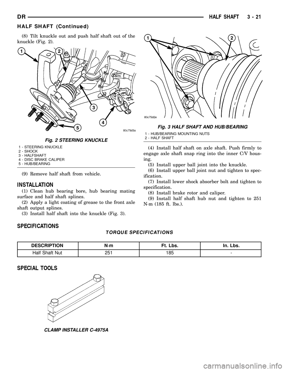
(8) Tilt knuckle out and push half shaft out of the
knuckle (Fig. 2).
(9) Remove half shaft from vehicle.
INSTALLATION
(1) Clean hub bearing bore, hub bearing mating
surface and half shaft splines.
(2) Apply a light coating of grease to the front axle
shaft output splines.
(3) Install half shaft into the knuckle (Fig. 3).(4) Install half shaft on axle shaft. Push firmly to
engage axle shaft snap ring into the inner C/V hous-
ing.
(5) Install upper ball joint into the knuckle.
(6) Install upper ball joint nut and tighten to spec-
ification.
(7) Install lower shock absorber bolt and tighten to
specification.
(8) Install brake rotor and caliper.
(9) Install half shaft hub nut and tighten to 251
N´m (185 ft. lbs.).
SPECIFICATIONS
TORQUE SPECIFICATIONS
DESCRIPTION N´m Ft. Lbs. In. Lbs.
Half Shaft Nut 251 185 -
SPECIAL TOOLS
Fig. 2 STEERING KNUCKLE
1 - STEERING KNUCKLE
2 - SHOCK
3 - HALFSHAFT
4 - DISC BRAKE CALIPER
5 - HUB/BEARING
Fig. 3 HALF SHAFT AND HUB/BEARING
1 - HUB/BEARING MOUNTING NUTS
2 - HALF SHAFT
CLAMP INSTALLER C-4975A
DRHALF SHAFT 3 - 21
HALF SHAFT (Continued)
Page 103 of 2627
CV JOINT-OUTER
REMOVAL
(1) Clamp shaft in a vise (with soft jaws) and sup-
port C/V joint.
CAUTION: Do not damage C/V housing or half
shaft.
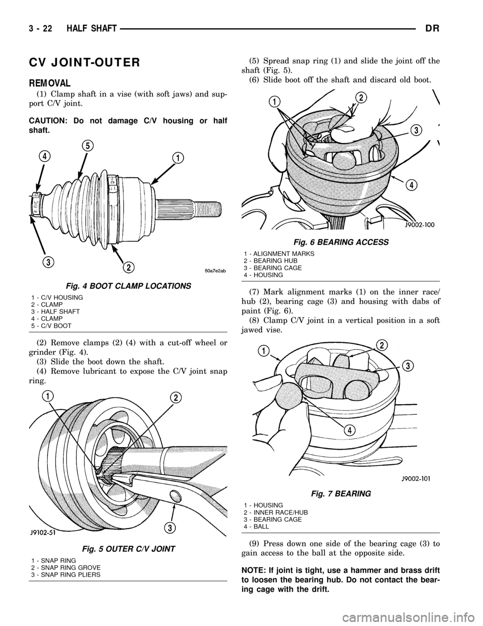
(2) Remove clamps (2) (4) with a cut-off wheel or
grinder (Fig. 4).
(3) Slide the boot down the shaft.
(4) Remove lubricant to expose the C/V joint snap
ring.(5) Spread snap ring (1) and slide the joint off the
shaft (Fig. 5).
(6) Slide boot off the shaft and discard old boot.
(7) Mark alignment marks (1) on the inner race/
hub (2), bearing cage (3) and housing with dabs of
paint (Fig. 6).
(8) Clamp C/V joint in a vertical position in a soft
jawed vise.
(9) Press down one side of the bearing cage (3) to
gain access to the ball at the opposite side.
NOTE: If joint is tight, use a hammer and brass drift
to loosen the bearing hub. Do not contact the bear-
ing cage with the drift.
Fig. 4 BOOT CLAMP LOCATIONS
1 - C/V HOUSING
2 - CLAMP
3 - HALF SHAFT
4 - CLAMP
5 - C/V BOOT
Fig. 5 OUTER C/V JOINT
1 - SNAP RING
2 - SNAP RING GROVE
3 - SNAP RING PLIERS
Fig. 6 BEARING ACCESS
1 - ALIGNMENT MARKS
2 - BEARING HUB
3 - BEARING CAGE
4 - HOUSING
Fig. 7 BEARING
1 - HOUSING
2 - INNER RACE/HUB
3 - BEARING CAGE
4 - BALL
3 - 22 HALF SHAFTDR
Page 104 of 2627
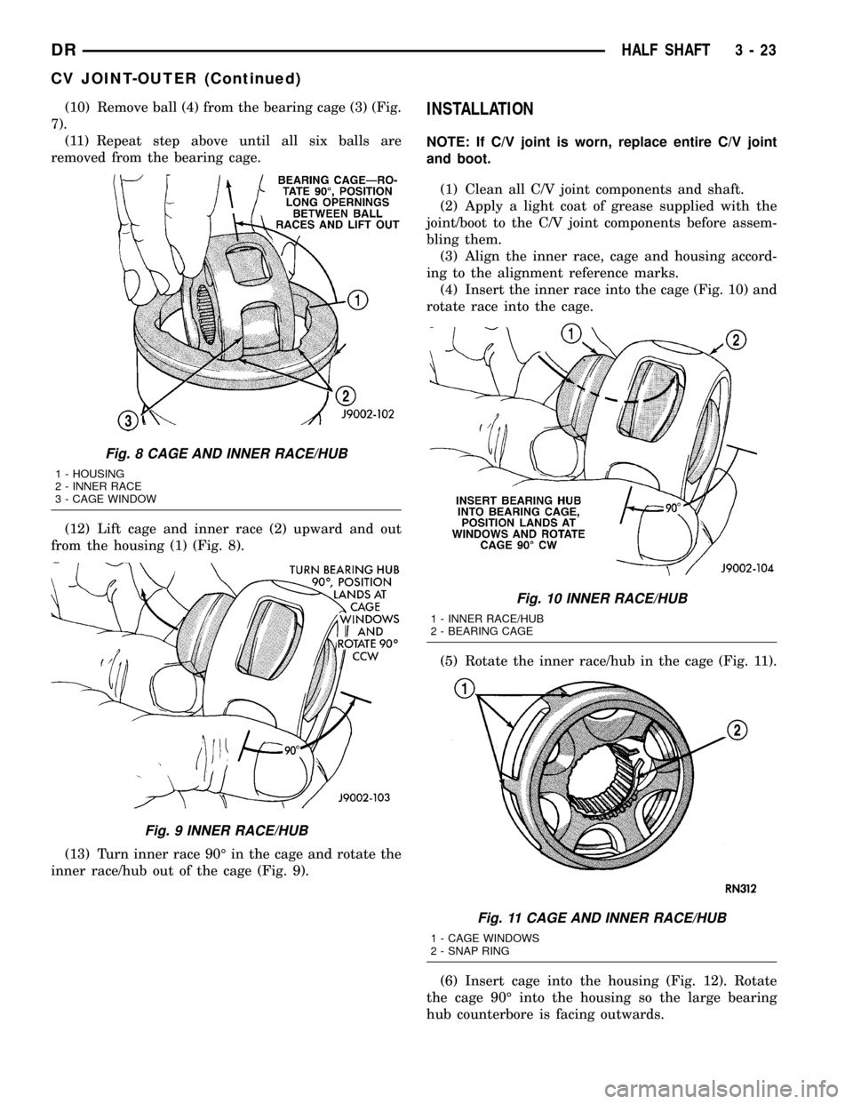
(10) Remove ball (4) from the bearing cage (3) (Fig.
7).
(11) Repeat step above until all six balls are
removed from the bearing cage.
(12) Lift cage and inner race (2) upward and out
from the housing (1) (Fig. 8).
(13) Turn inner race 90É in the cage and rotate the
inner race/hub out of the cage (Fig. 9).INSTALLATION
NOTE: If C/V joint is worn, replace entire C/V joint
and boot.
(1) Clean all C/V joint components and shaft.
(2) Apply a light coat of grease supplied with the
joint/boot to the C/V joint components before assem-
bling them.
(3) Align the inner race, cage and housing accord-
ing to the alignment reference marks.
(4) Insert the inner race into the cage (Fig. 10) and
rotate race into the cage.
(5) Rotate the inner race/hub in the cage (Fig. 11).
(6) Insert cage into the housing (Fig. 12). Rotate
the cage 90É into the housing so the large bearing
hub counterbore is facing outwards.
Fig. 8 CAGE AND INNER RACE/HUB
1 - HOUSING
2 - INNER RACE
3 - CAGE WINDOW
Fig. 9 INNER RACE/HUB
Fig. 10 INNER RACE/HUB
1 - INNER RACE/HUB
2 - BEARING CAGE
Fig. 11 CAGE AND INNER RACE/HUB
1 - CAGE WINDOWS
2 - SNAP RING
DRHALF SHAFT 3 - 23
CV JOINT-OUTER (Continued)
Page 105 of 2627
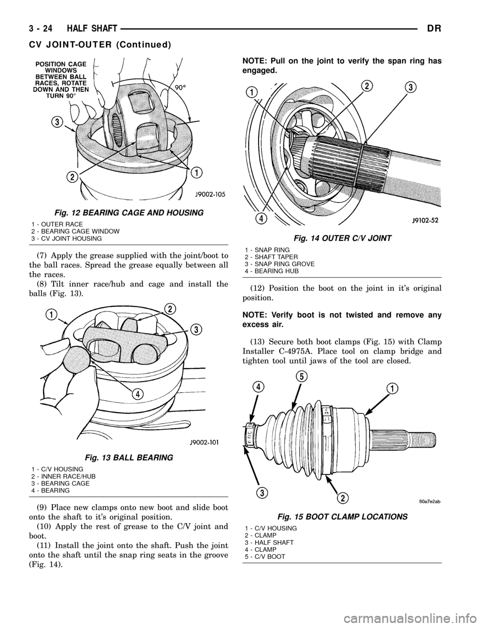
(7) Apply the grease supplied with the joint/boot to
the ball races. Spread the grease equally between all
the races.
(8) Tilt inner race/hub and cage and install the
balls (Fig. 13).
(9) Place new clamps onto new boot and slide boot
onto the shaft to it's original position.
(10) Apply the rest of grease to the C/V joint and
boot.
(11) Install the joint onto the shaft. Push the joint
onto the shaft until the snap ring seats in the groove
(Fig. 14).NOTE: Pull on the joint to verify the span ring has
engaged.
(12) Position the boot on the joint in it's original
position.
NOTE: Verify boot is not twisted and remove any
excess air.
(13) Secure both boot clamps (Fig. 15) with Clamp
Installer C-4975A. Place tool on clamp bridge and
tighten tool until jaws of the tool are closed.
Fig. 12 BEARING CAGE AND HOUSING
1 - OUTER RACE
2 - BEARING CAGE WINDOW
3 - CV JOINT HOUSING
Fig. 13 BALL BEARING
1 - C/V HOUSING
2 - INNER RACE/HUB
3 - BEARING CAGE
4 - BEARING
Fig. 14 OUTER C/V JOINT
1 - SNAP RING
2 - SHAFT TAPER
3 - SNAP RING GROVE
4 - BEARING HUB
Fig. 15 BOOT CLAMP LOCATIONS
1 - C/V HOUSING
2 - CLAMP
3 - HALF SHAFT
4 - CLAMP
5 - C/V BOOT
3 - 24 HALF SHAFTDR
CV JOINT-OUTER (Continued)
Page 106 of 2627
CV JOINT-INNER
REMOVAL
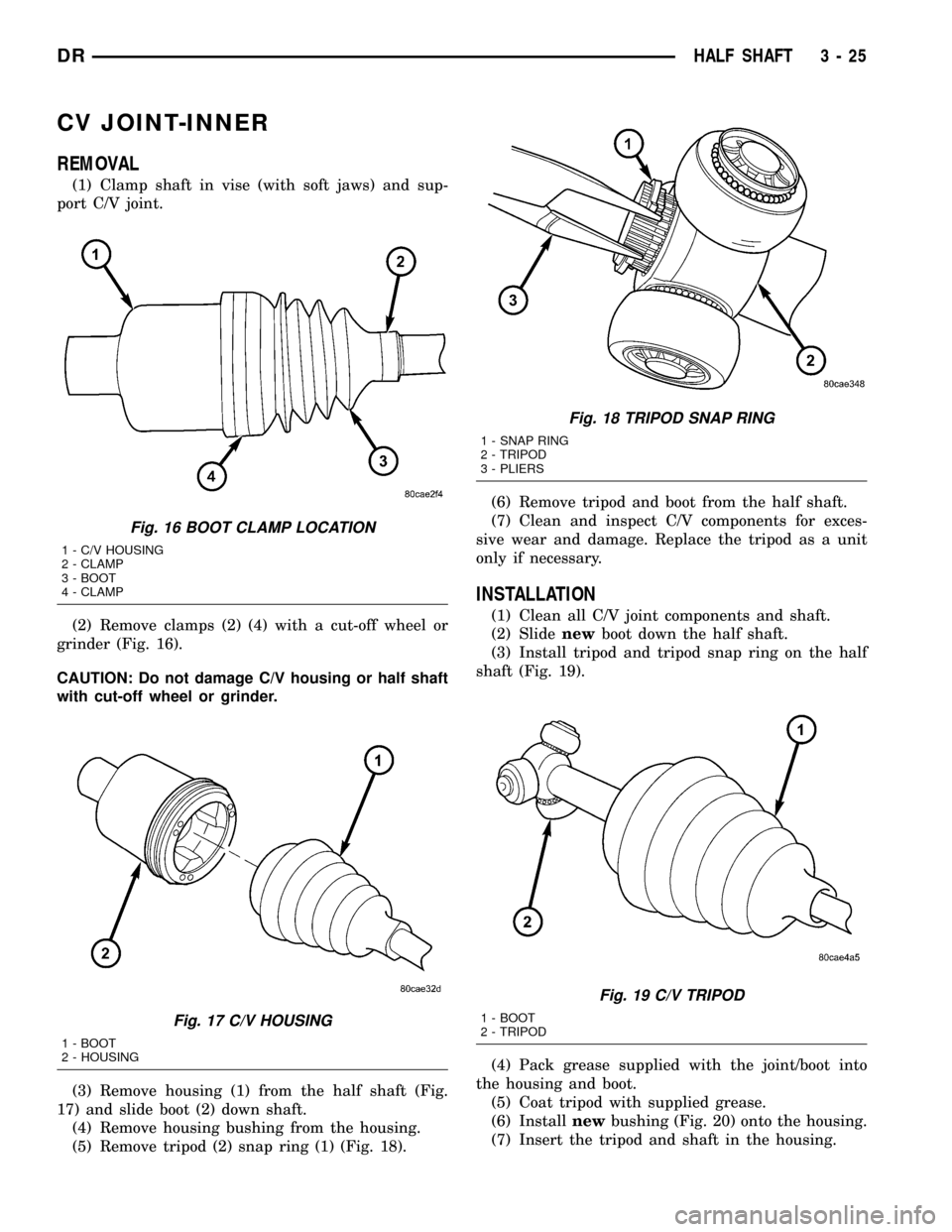
(1) Clamp shaft in vise (with soft jaws) and sup-
port C/V joint.
(2) Remove clamps (2) (4) with a cut-off wheel or
grinder (Fig. 16).
CAUTION: Do not damage C/V housing or half shaft
with cut-off wheel or grinder.
(3) Remove housing (1) from the half shaft (Fig.
17) and slide boot (2) down shaft.
(4) Remove housing bushing from the housing.
(5) Remove tripod (2) snap ring (1) (Fig. 18).(6) Remove tripod and boot from the half shaft.
(7) Clean and inspect C/V components for exces-
sive wear and damage. Replace the tripod as a unit
only if necessary.
INSTALLATION
(1) Clean all C/V joint components and shaft.
(2) Slidenewboot down the half shaft.
(3) Install tripod and tripod snap ring on the half
shaft (Fig. 19).
(4) Pack grease supplied with the joint/boot into
the housing and boot.
(5) Coat tripod with supplied grease.
(6) Installnewbushing (Fig. 20) onto the housing.
(7) Insert the tripod and shaft in the housing.
Fig. 16 BOOT CLAMP LOCATION
1 - C/V HOUSING
2 - CLAMP
3 - BOOT
4 - CLAMP
Fig. 17 C/V HOUSING
1 - BOOT
2 - HOUSING
Fig. 18 TRIPOD SNAP RING
1 - SNAP RING
2 - TRIPOD
3 - PLIERS
Fig. 19 C/V TRIPOD
1 - BOOT
2 - TRIPOD
DRHALF SHAFT 3 - 25
Page 107 of 2627
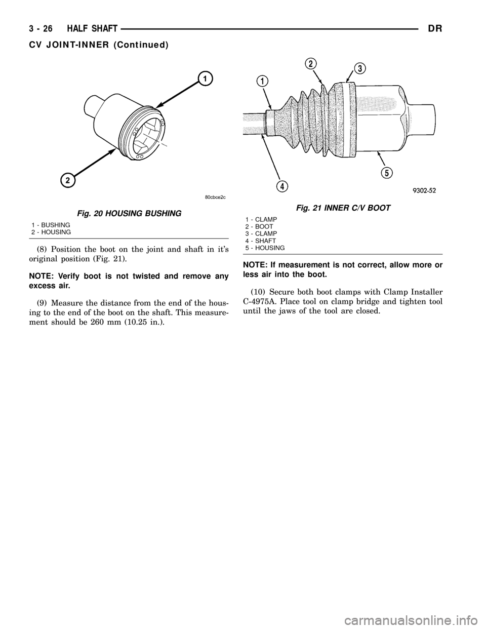
(8) Position the boot on the joint and shaft in it's
original position (Fig. 21).
NOTE: Verify boot is not twisted and remove any
excess air.
(9) Measure the distance from the end of the hous-
ing to the end of the boot on the shaft. This measure-
ment should be 260 mm (10.25 in.).NOTE: If measurement is not correct, allow more or
less air into the boot.
(10) Secure both boot clamps with Clamp Installer
C-4975A. Place tool on clamp bridge and tighten tool
until the jaws of the tool are closed.
Fig. 20 HOUSING BUSHING
1 - BUSHING
2 - HOUSING
Fig. 21 INNER C/V BOOT
1 - CLAMP
2 - BOOT
3 - CLAMP
4 - SHAFT
5 - HOUSING
3 - 26 HALF SHAFTDR
CV JOINT-INNER (Continued)
Page 112 of 2627
REMOVAL
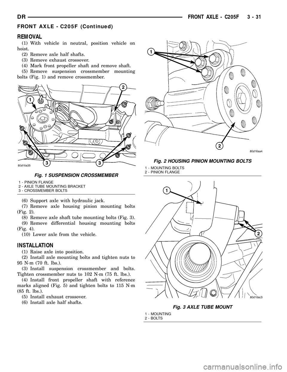
(1) With vehicle in neutral, position vehicle on
hoist.
(2) Remove axle half shafts.
(3) Remove exhaust crossover.
(4) Mark front propeller shaft and remove shaft.
(5) Remove suspension crossmember mounting
bolts (Fig. 1) and remove crossmember.
(6) Support axle with hydraulic jack.
(7) Remove axle housing pinion mounting bolts
(Fig. 2).
(8) Remove axle shaft tube mounting bolts (Fig. 3).
(9) Remove differential housing mounting bolts
(Fig. 4).
(10) Lower axle from the vehicle.
INSTALLATION
(1) Raise axle into position.
(2) Install axle mounting bolts and tighten nuts to
95 N´m (70 ft. lbs.).
(3) Install suspension crossmember and bolts.
Tighten crossmember nuts to 102 N´m (75 ft. lbs.).
(4) Install front propeller shaft with reference
marks aligned (Fig. 5) and tighten bolts to 115 N´m
(85 ft. lbs.).
(5) Install exhaust crossover.
(6) Install axle half shafts.
Fig. 1 SUSPENSION CROSSMEMBER
1 - PINION FLANGE
2 - AXLE TUBE MOUNTING BRACKET
3 - CROSSMEMBER BOLTS
Fig. 2 HOUSING PINION MOUNTING BOLTS
1 - MOUNTING BOLTS
2 - PINION FLANGE
Fig. 3 AXLE TUBE MOUNT
1 - MOUNTING
2 - BOLTS
DRFRONT AXLE - C205F 3 - 31
FRONT AXLE - C205F (Continued)
Page 113 of 2627
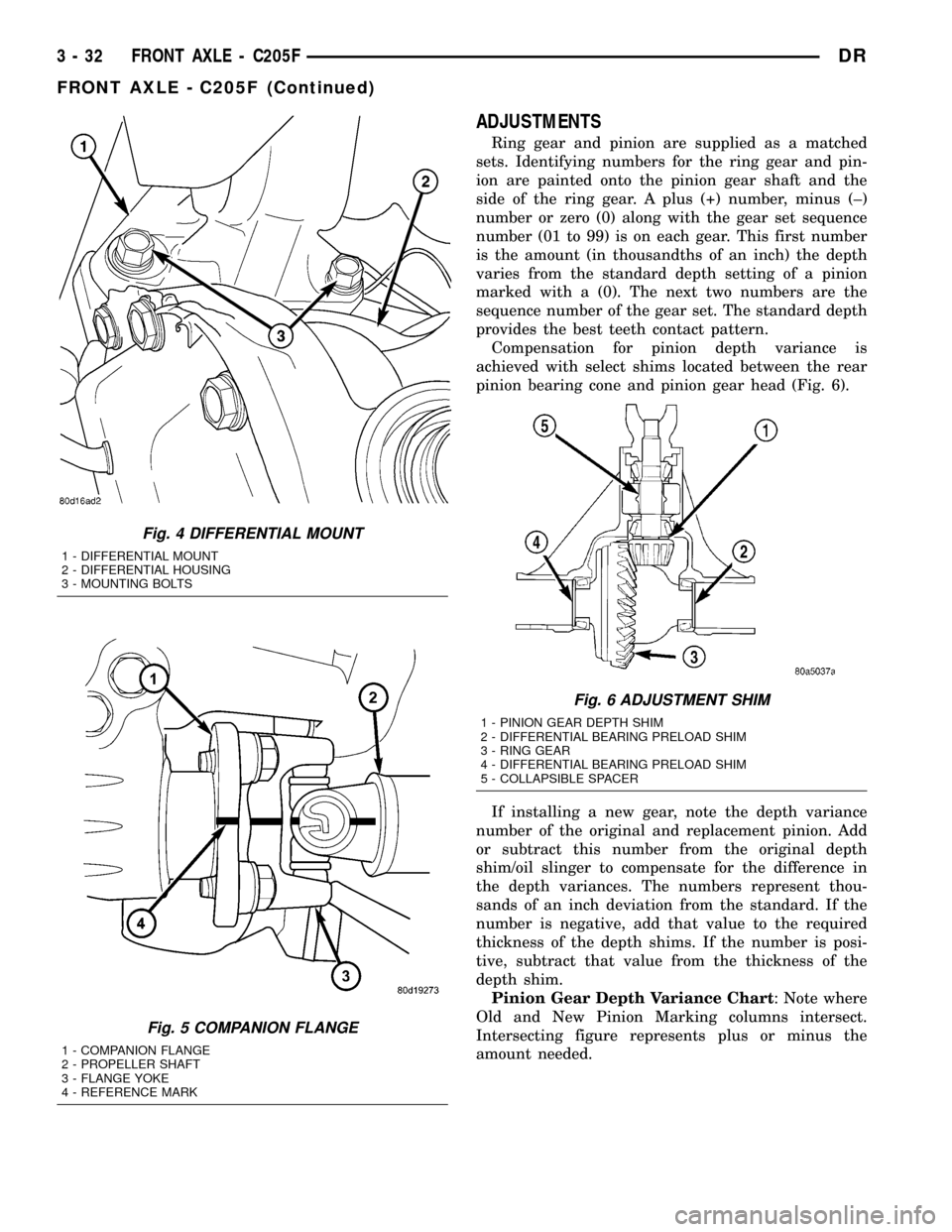
ADJUSTMENTS
Ring gear and pinion are supplied as a matched
sets. Identifying numbers for the ring gear and pin-
ion are painted onto the pinion gear shaft and the
side of the ring gear. A plus (+) number, minus (±)
number or zero (0) along with the gear set sequence
number (01 to 99) is on each gear. This first number
is the amount (in thousandths of an inch) the depth
varies from the standard depth setting of a pinion
marked with a (0). The next two numbers are the
sequence number of the gear set. The standard depth
provides the best teeth contact pattern.
Compensation for pinion depth variance is
achieved with select shims located between the rear
pinion bearing cone and pinion gear head (Fig. 6).
If installing a new gear, note the depth variance
number of the original and replacement pinion. Add
or subtract this number from the original depth
shim/oil slinger to compensate for the difference in
the depth variances. The numbers represent thou-
sands of an inch deviation from the standard. If the
number is negative, add that value to the required
thickness of the depth shims. If the number is posi-
tive, subtract that value from the thickness of the
depth shim.
Pinion Gear Depth Variance Chart: Note where
Old and New Pinion Marking columns intersect.
Intersecting figure represents plus or minus the
amount needed.
Fig. 4 DIFFERENTIAL MOUNT
1 - DIFFERENTIAL MOUNT
2 - DIFFERENTIAL HOUSING
3 - MOUNTING BOLTS
Fig. 5 COMPANION FLANGE
1 - COMPANION FLANGE
2 - PROPELLER SHAFT
3 - FLANGE YOKE
4 - REFERENCE MARK
Fig. 6 ADJUSTMENT SHIM
1 - PINION GEAR DEPTH SHIM
2 - DIFFERENTIAL BEARING PRELOAD SHIM
3 - RING GEAR
4 - DIFFERENTIAL BEARING PRELOAD SHIM
5 - COLLAPSIBLE SPACER
3 - 32 FRONT AXLE - C205FDR
FRONT AXLE - C205F (Continued)
Page 114 of 2627
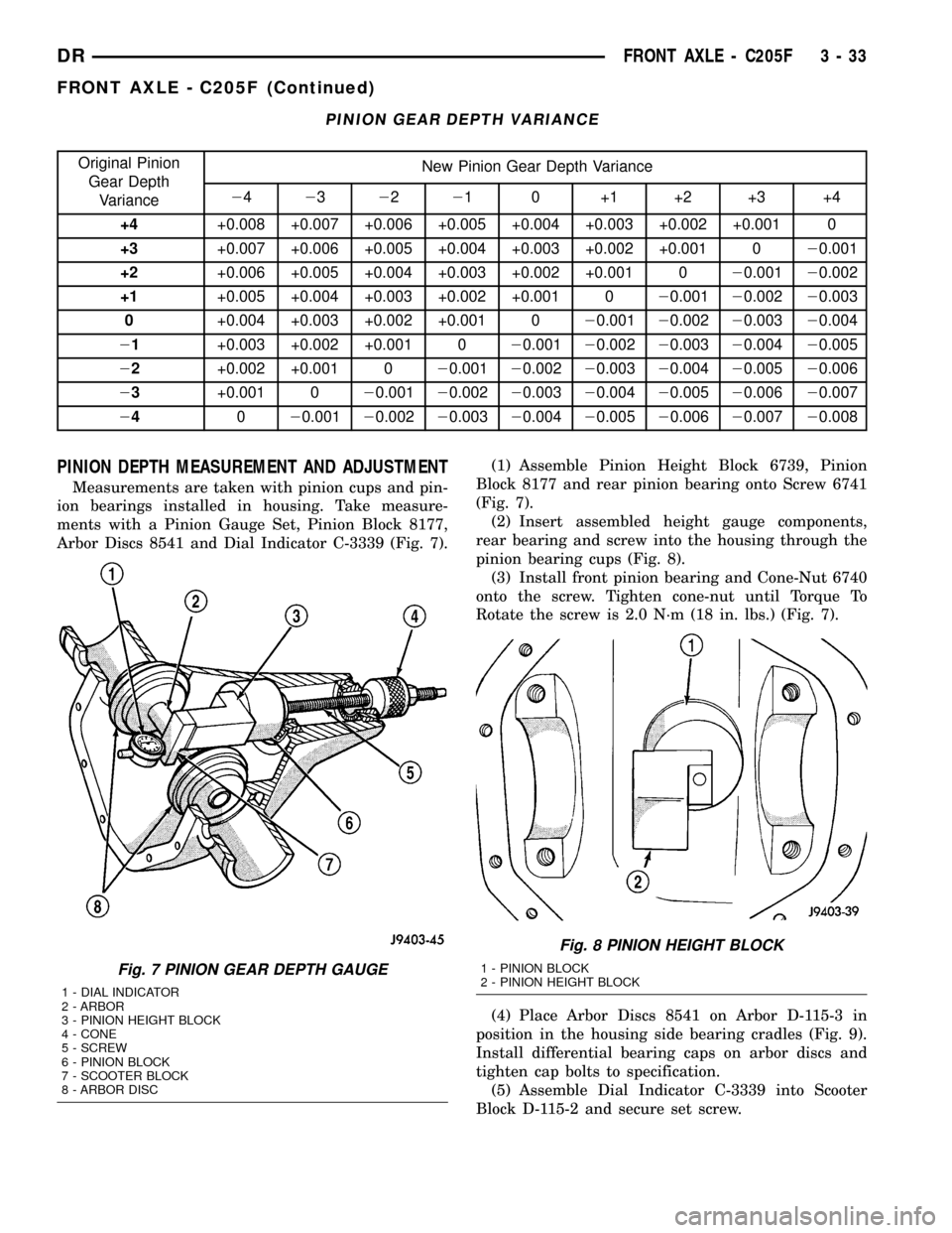
PINION GEAR DEPTH VARIANCE
Original Pinion
Gear Depth
VarianceNew Pinion Gear Depth Variance
24232221 0 +1 +2 +3 +4
+4+0.008 +0.007 +0.006 +0.005 +0.004 +0.003 +0.002 +0.001 0
+3+0.007 +0.006 +0.005 +0.004 +0.003 +0.002 +0.001 020.001
+2+0.006 +0.005 +0.004 +0.003 +0.002 +0.001 020.00120.002
+1+0.005 +0.004 +0.003 +0.002 +0.001 020.00120.00220.003
0+0.004 +0.003 +0.002 +0.001 020.00120.00220.00320.004
21+0.003 +0.002 +0.001 020.00120.00220.00320.00420.005
22+0.002 +0.001 020.00120.00220.00320.00420.00520.006
23+0.001 020.00120.00220.00320.00420.00520.00620.007
24020.00120.00220.00320.00420.00520.00620.00720.008
PINION DEPTH MEASUREMENT AND ADJUSTMENT
Measurements are taken with pinion cups and pin-
ion bearings installed in housing. Take measure-
ments with a Pinion Gauge Set, Pinion Block 8177,
Arbor Discs 8541 and Dial Indicator C-3339 (Fig. 7).(1) Assemble Pinion Height Block 6739, Pinion
Block 8177 and rear pinion bearing onto Screw 6741
(Fig. 7).
(2) Insert assembled height gauge components,
rear bearing and screw into the housing through the
pinion bearing cups (Fig. 8).
(3) Install front pinion bearing and Cone-Nut 6740
onto the screw. Tighten cone-nut until Torque To
Rotate the screw is 2.0 N´m (18 in. lbs.) (Fig. 7).
(4) Place Arbor Discs 8541 on Arbor D-115-3 in
position in the housing side bearing cradles (Fig. 9).
Install differential bearing caps on arbor discs and
tighten cap bolts to specification.
(5) Assemble Dial Indicator C-3339 into Scooter
Block D-115-2 and secure set screw.
Fig. 7 PINION GEAR DEPTH GAUGE
1 - DIAL INDICATOR
2 - ARBOR
3 - PINION HEIGHT BLOCK
4 - CONE
5 - SCREW
6 - PINION BLOCK
7 - SCOOTER BLOCK
8 - ARBOR DISC
Fig. 8 PINION HEIGHT BLOCK
1 - PINION BLOCK
2 - PINION HEIGHT BLOCK
DRFRONT AXLE - C205F 3 - 33
FRONT AXLE - C205F (Continued)