Fig DODGE RAM 1500 1998 2.G Manual Online
[x] Cancel search | Manufacturer: DODGE, Model Year: 1998, Model line: RAM 1500, Model: DODGE RAM 1500 1998 2.GPages: 2627
Page 115 of 2627
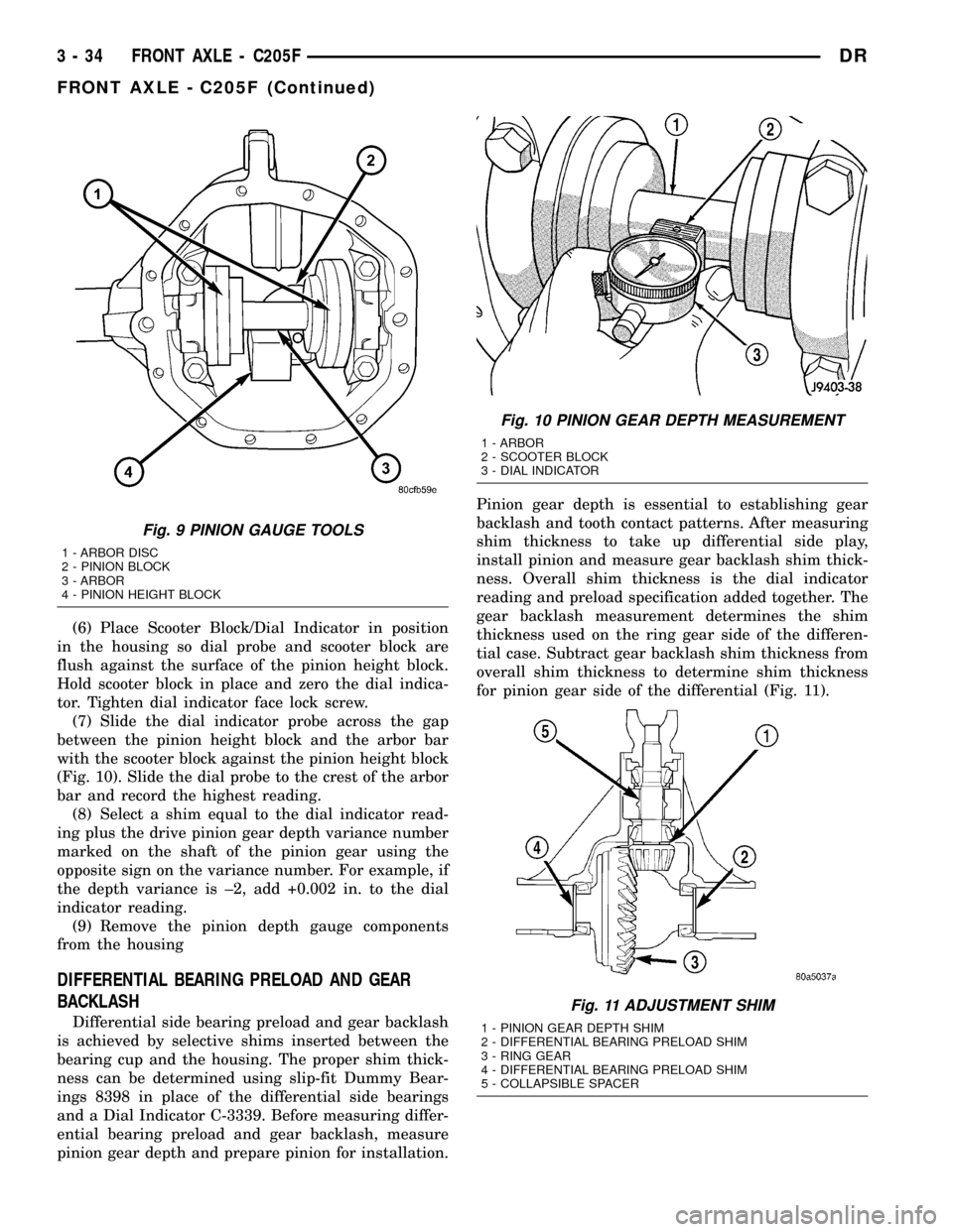
(6) Place Scooter Block/Dial Indicator in position
in the housing so dial probe and scooter block are
flush against the surface of the pinion height block.
Hold scooter block in place and zero the dial indica-
tor. Tighten dial indicator face lock screw.
(7) Slide the dial indicator probe across the gap
between the pinion height block and the arbor bar
with the scooter block against the pinion height block
(Fig. 10). Slide the dial probe to the crest of the arbor
bar and record the highest reading.
(8) Select a shim equal to the dial indicator read-
ing plus the drive pinion gear depth variance number
marked on the shaft of the pinion gear using the
opposite sign on the variance number. For example, if
the depth variance is ±2, add +0.002 in. to the dial
indicator reading.
(9) Remove the pinion depth gauge components
from the housing
DIFFERENTIAL BEARING PRELOAD AND GEAR
BACKLASH
Differential side bearing preload and gear backlash
is achieved by selective shims inserted between the
bearing cup and the housing. The proper shim thick-
ness can be determined using slip-fit Dummy Bear-
ings 8398 in place of the differential side bearings
and a Dial Indicator C-3339. Before measuring differ-
ential bearing preload and gear backlash, measure
pinion gear depth and prepare pinion for installation.Pinion gear depth is essential to establishing gear
backlash and tooth contact patterns. After measuring
shim thickness to take up differential side play,
install pinion and measure gear backlash shim thick-
ness. Overall shim thickness is the dial indicator
reading and preload specification added together. The
gear backlash measurement determines the shim
thickness used on the ring gear side of the differen-
tial case. Subtract gear backlash shim thickness from
overall shim thickness to determine shim thickness
for pinion gear side of the differential (Fig. 11).
Fig. 9 PINION GAUGE TOOLS
1 - ARBOR DISC
2 - PINION BLOCK
3 - ARBOR
4 - PINION HEIGHT BLOCK
Fig. 10 PINION GEAR DEPTH MEASUREMENT
1 - ARBOR
2 - SCOOTER BLOCK
3 - DIAL INDICATOR
Fig. 11 ADJUSTMENT SHIM
1 - PINION GEAR DEPTH SHIM
2 - DIFFERENTIAL BEARING PRELOAD SHIM
3 - RING GEAR
4 - DIFFERENTIAL BEARING PRELOAD SHIM
5 - COLLAPSIBLE SPACER
3 - 34 FRONT AXLE - C205FDR
FRONT AXLE - C205F (Continued)
Page 116 of 2627
SHIM SELECTION
NOTE: It is difficult to salvage the differential side
bearings during the removal procedure. Install
replacement bearings if necessary.
(1) Remove side bearings from differential case.
(2) Install ring gear if necessary, on differential
case and tighten bolts to specification.
(3) Install Dummy Bearings 8398 on differential
case.
(4) Install differential case in the housing.
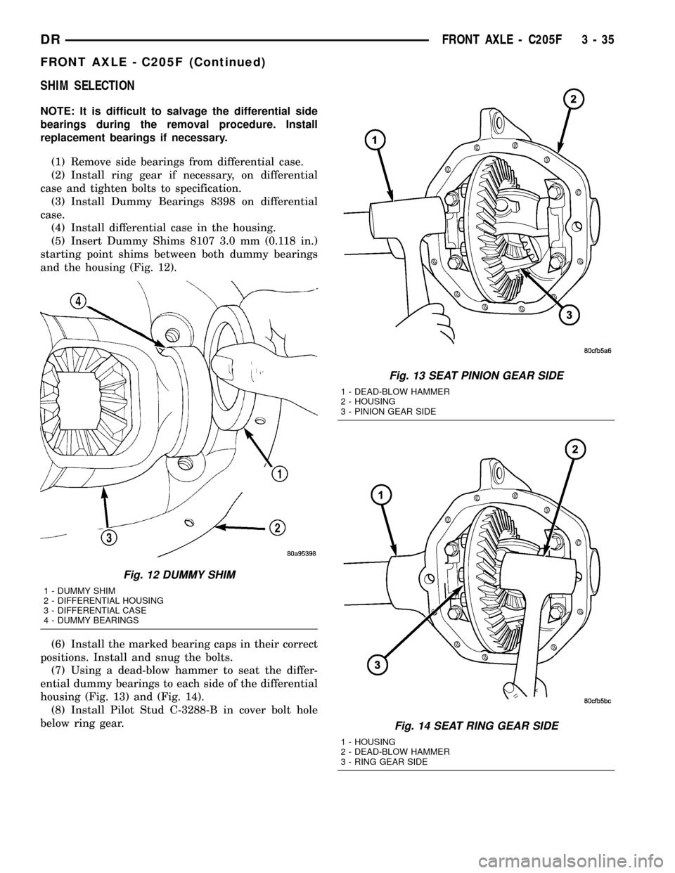
(5) Insert Dummy Shims 8107 3.0 mm (0.118 in.)
starting point shims between both dummy bearings
and the housing (Fig. 12).
(6) Install the marked bearing caps in their correct
positions. Install and snug the bolts.
(7) Using a dead-blow hammer to seat the differ-
ential dummy bearings to each side of the differential
housing (Fig. 13) and (Fig. 14).
(8) Install Pilot Stud C-3288-B in cover bolt hole
below ring gear.
Fig. 12 DUMMY SHIM
1 - DUMMY SHIM
2 - DIFFERENTIAL HOUSING
3 - DIFFERENTIAL CASE
4 - DUMMY BEARINGS
Fig. 13 SEAT PINION GEAR SIDE
1 - DEAD-BLOW HAMMER
2 - HOUSING
3 - PINION GEAR SIDE
Fig. 14 SEAT RING GEAR SIDE
1 - HOUSING
2 - DEAD-BLOW HAMMER
3 - RING GEAR SIDE
DRFRONT AXLE - C205F 3 - 35
FRONT AXLE - C205F (Continued)
Page 117 of 2627
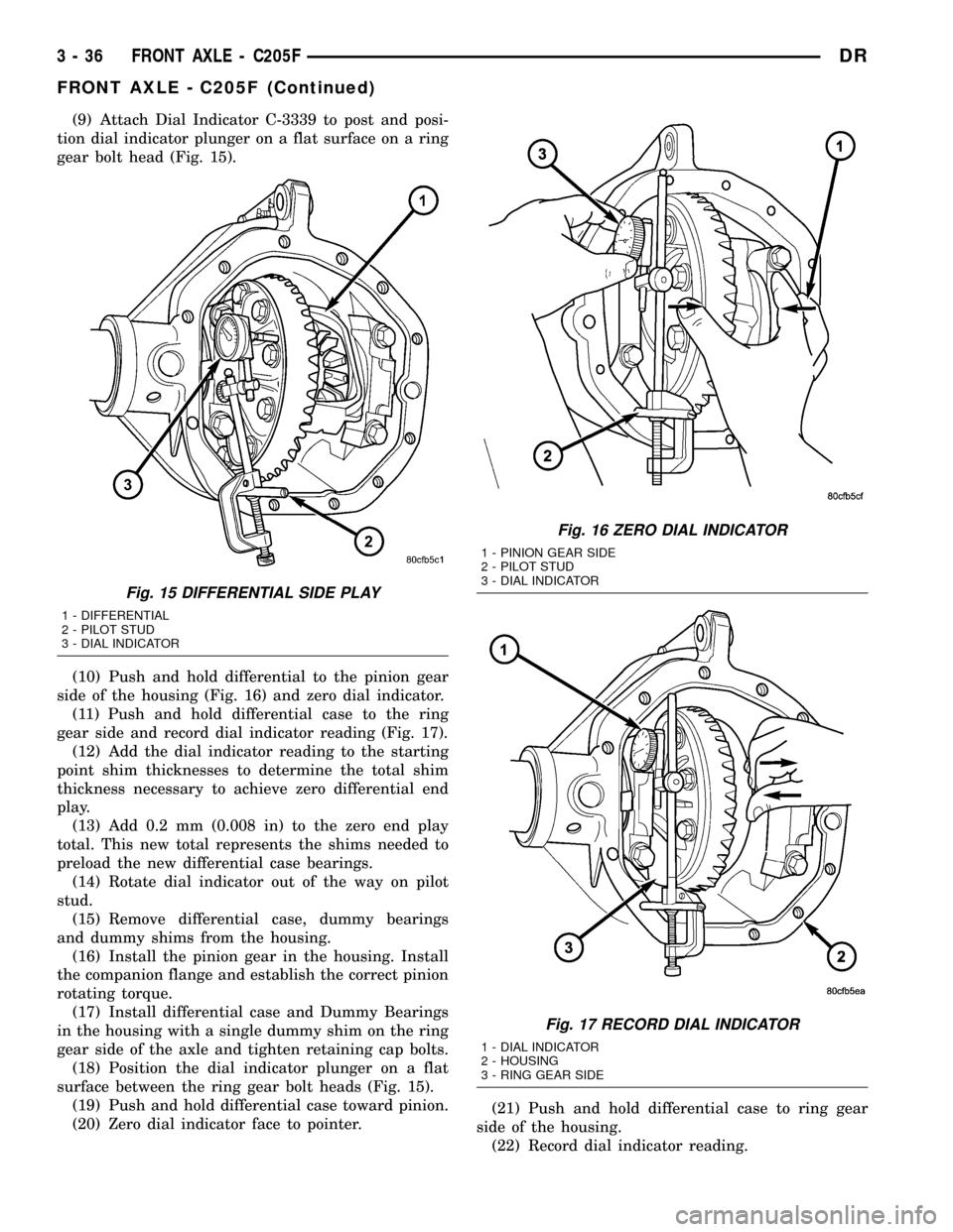
(9) Attach Dial Indicator C-3339 to post and posi-
tion dial indicator plunger on a flat surface on a ring
gear bolt head (Fig. 15).
(10) Push and hold differential to the pinion gear
side of the housing (Fig. 16) and zero dial indicator.
(11) Push and hold differential case to the ring
gear side and record dial indicator reading (Fig. 17).
(12) Add the dial indicator reading to the starting
point shim thicknesses to determine the total shim
thickness necessary to achieve zero differential end
play.
(13) Add 0.2 mm (0.008 in) to the zero end play
total. This new total represents the shims needed to
preload the new differential case bearings.
(14) Rotate dial indicator out of the way on pilot
stud.
(15) Remove differential case, dummy bearings
and dummy shims from the housing.
(16) Install the pinion gear in the housing. Install
the companion flange and establish the correct pinion
rotating torque.
(17) Install differential case and Dummy Bearings
in the housing with a single dummy shim on the ring
gear side of the axle and tighten retaining cap bolts.
(18) Position the dial indicator plunger on a flat
surface between the ring gear bolt heads (Fig. 15).
(19) Push and hold differential case toward pinion.
(20) Zero dial indicator face to pointer.(21) Push and hold differential case to ring gear
side of the housing.
(22) Record dial indicator reading.
Fig. 15 DIFFERENTIAL SIDE PLAY
1 - DIFFERENTIAL
2 - PILOT STUD
3 - DIAL INDICATOR
Fig. 16 ZERO DIAL INDICATOR
1 - PINION GEAR SIDE
2 - PILOT STUD
3 - DIAL INDICATOR
Fig. 17 RECORD DIAL INDICATOR
1 - DIAL INDICATOR
2 - HOUSING
3 - RING GEAR SIDE
3 - 36 FRONT AXLE - C205FDR
FRONT AXLE - C205F (Continued)
Page 118 of 2627
(23) Subtract 0.05 mm (0.002 in.) from the dial
indicator reading to compensate for backlash between
ring and pinion gears. Add the resulting measure-
ment to the thickness of the single dummy shim.
This is the thickness of shim required to achieve
proper backlash.
(24) Subtract the backlash shim thickness from
the total preload shim thickness. The remainder is
the shim thickness required on the pinion side of the
housing.
(25) Rotate dial indicator out of the way on pilot
stud.
(26) Remove differential case, dummy bearings
and dummy shim from the housing.
(27) Install new side bearing cones and cups on
differential case.
(28) Install Spreader W-129-B and Adapter Plates
8142-A on the housing and spread open enough to
receive differential case.
CAUTION: Never spread over 0.50 mm (0.020 in). If
the housing is over-spread, it could be distorted or
damaged.
(29) Place the side bearing shims in the differen-
tial housing against the housing shoulder.
(30) Install the differential case in the housing.
(31) Rotate the differential case several times to
seat the side bearings.
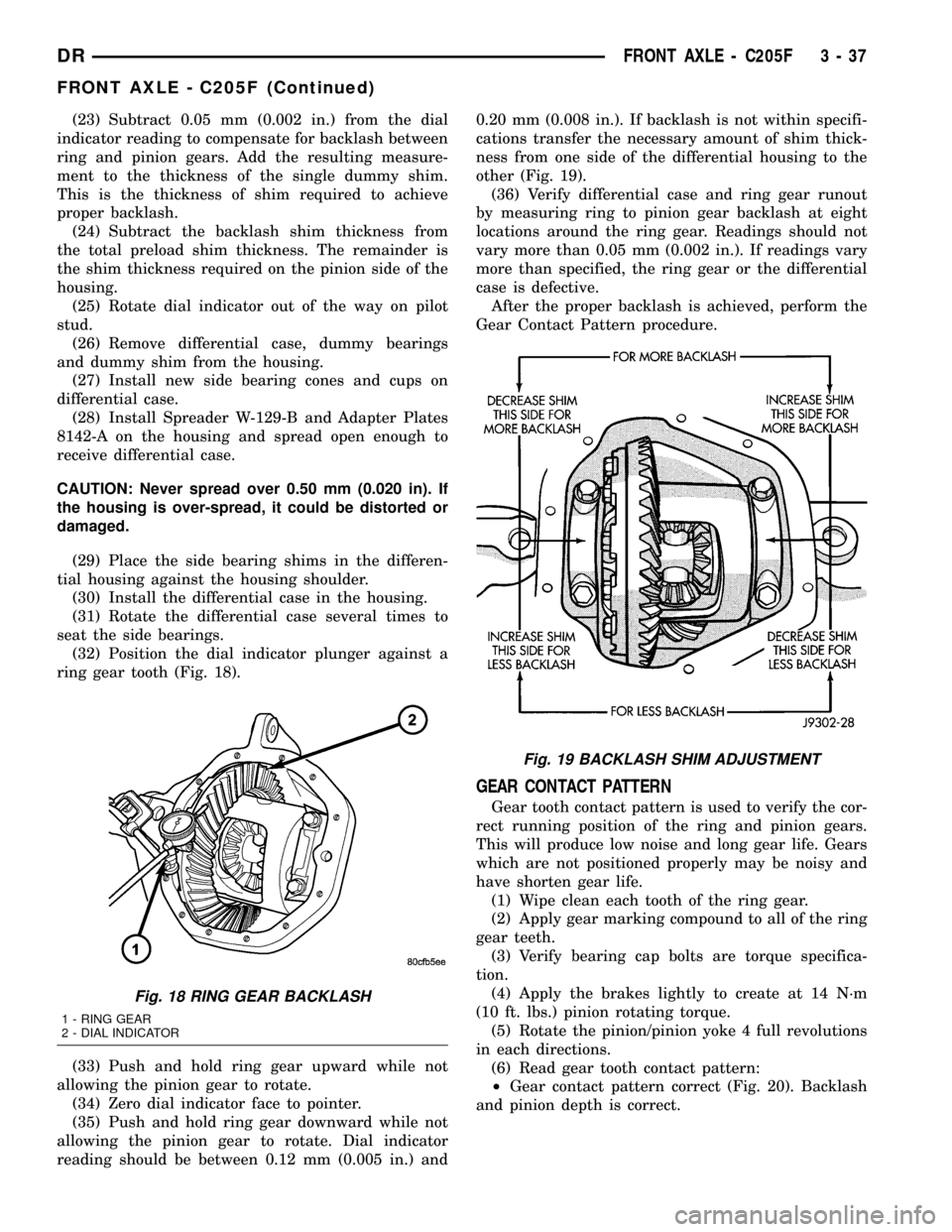
(32) Position the dial indicator plunger against a
ring gear tooth (Fig. 18).
(33) Push and hold ring gear upward while not
allowing the pinion gear to rotate.
(34) Zero dial indicator face to pointer.
(35) Push and hold ring gear downward while not
allowing the pinion gear to rotate. Dial indicator
reading should be between 0.12 mm (0.005 in.) and0.20 mm (0.008 in.). If backlash is not within specifi-
cations transfer the necessary amount of shim thick-
ness from one side of the differential housing to the
other (Fig. 19).
(36) Verify differential case and ring gear runout
by measuring ring to pinion gear backlash at eight
locations around the ring gear. Readings should not
vary more than 0.05 mm (0.002 in.). If readings vary
more than specified, the ring gear or the differential
case is defective.
After the proper backlash is achieved, perform the
Gear Contact Pattern procedure.
GEAR CONTACT PATTERN
Gear tooth contact pattern is used to verify the cor-
rect running position of the ring and pinion gears.
This will produce low noise and long gear life. Gears
which are not positioned properly may be noisy and
have shorten gear life.
(1) Wipe clean each tooth of the ring gear.
(2) Apply gear marking compound to all of the ring
gear teeth.
(3) Verify bearing cap bolts are torque specifica-
tion.
(4) Apply the brakes lightly to create at 14 N´m
(10 ft. lbs.) pinion rotating torque.
(5) Rotate the pinion/pinion yoke 4 full revolutions
in each directions.
(6) Read gear tooth contact pattern:
²Gear contact pattern correct (Fig. 20). Backlash
and pinion depth is correct.
Fig. 18 RING GEAR BACKLASH
1 - RING GEAR
2 - DIAL INDICATOR
Fig. 19 BACKLASH SHIM ADJUSTMENT
DRFRONT AXLE - C205F 3 - 37
FRONT AXLE - C205F (Continued)
Page 119 of 2627
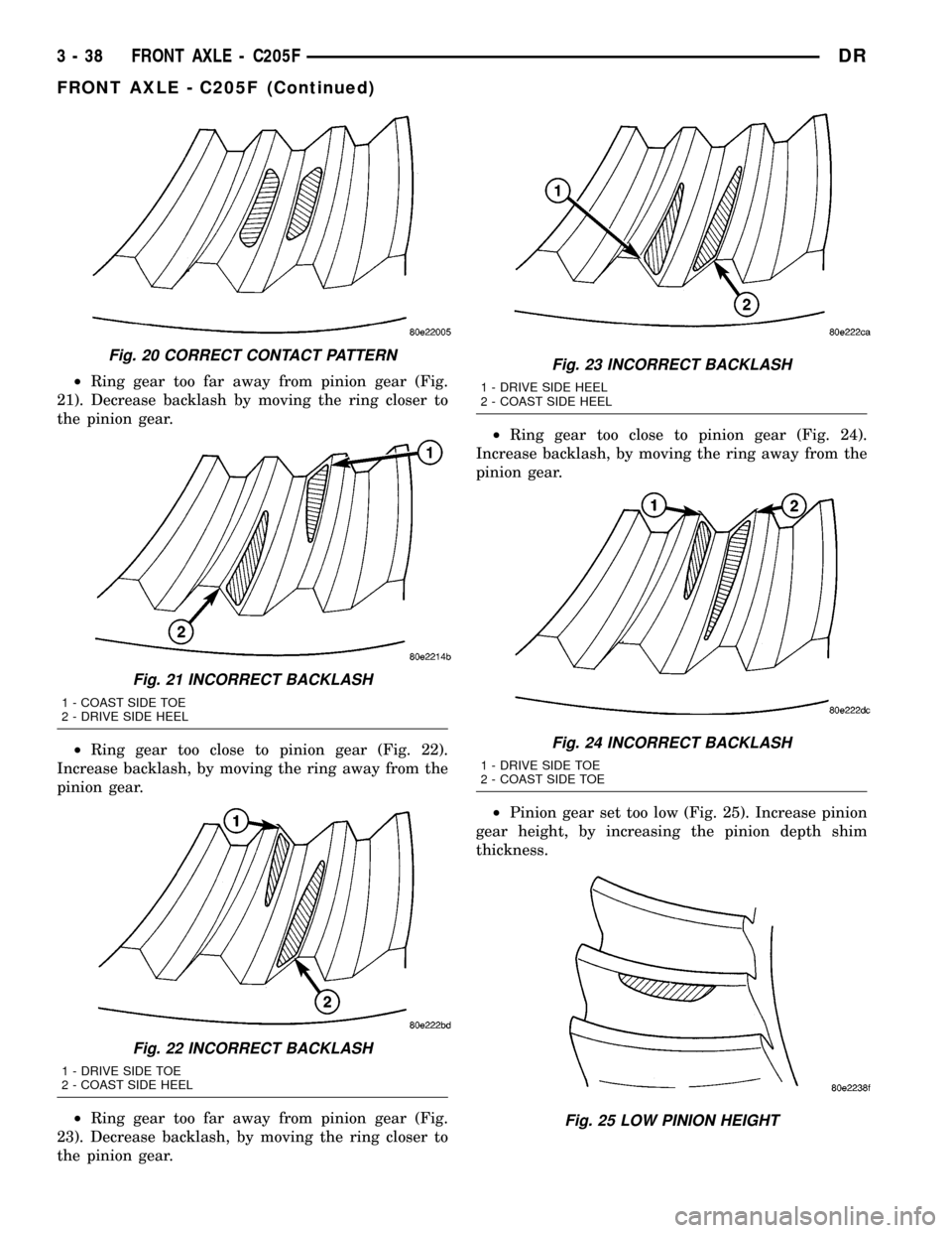
²Ring gear too far away from pinion gear (Fig.
21). Decrease backlash by moving the ring closer to
the pinion gear.
²Ring gear too close to pinion gear (Fig. 22).
Increase backlash, by moving the ring away from the
pinion gear.
²Ring gear too far away from pinion gear (Fig.
23). Decrease backlash, by moving the ring closer to
the pinion gear.²Ring gear too close to pinion gear (Fig. 24).
Increase backlash, by moving the ring away from the
pinion gear.
²Pinion gear set too low (Fig. 25). Increase pinion
gear height, by increasing the pinion depth shim
thickness.
Fig. 20 CORRECT CONTACT PATTERN
Fig. 21 INCORRECT BACKLASH
1 - COAST SIDE TOE
2 - DRIVE SIDE HEEL
Fig. 22 INCORRECT BACKLASH
1 - DRIVE SIDE TOE
2 - COAST SIDE HEEL
Fig. 23 INCORRECT BACKLASH
1 - DRIVE SIDE HEEL
2 - COAST SIDE HEEL
Fig. 24 INCORRECT BACKLASH
1 - DRIVE SIDE TOE
2 - COAST SIDE TOE
Fig. 25 LOW PINION HEIGHT
3 - 38 FRONT AXLE - C205FDR
FRONT AXLE - C205F (Continued)
Page 120 of 2627
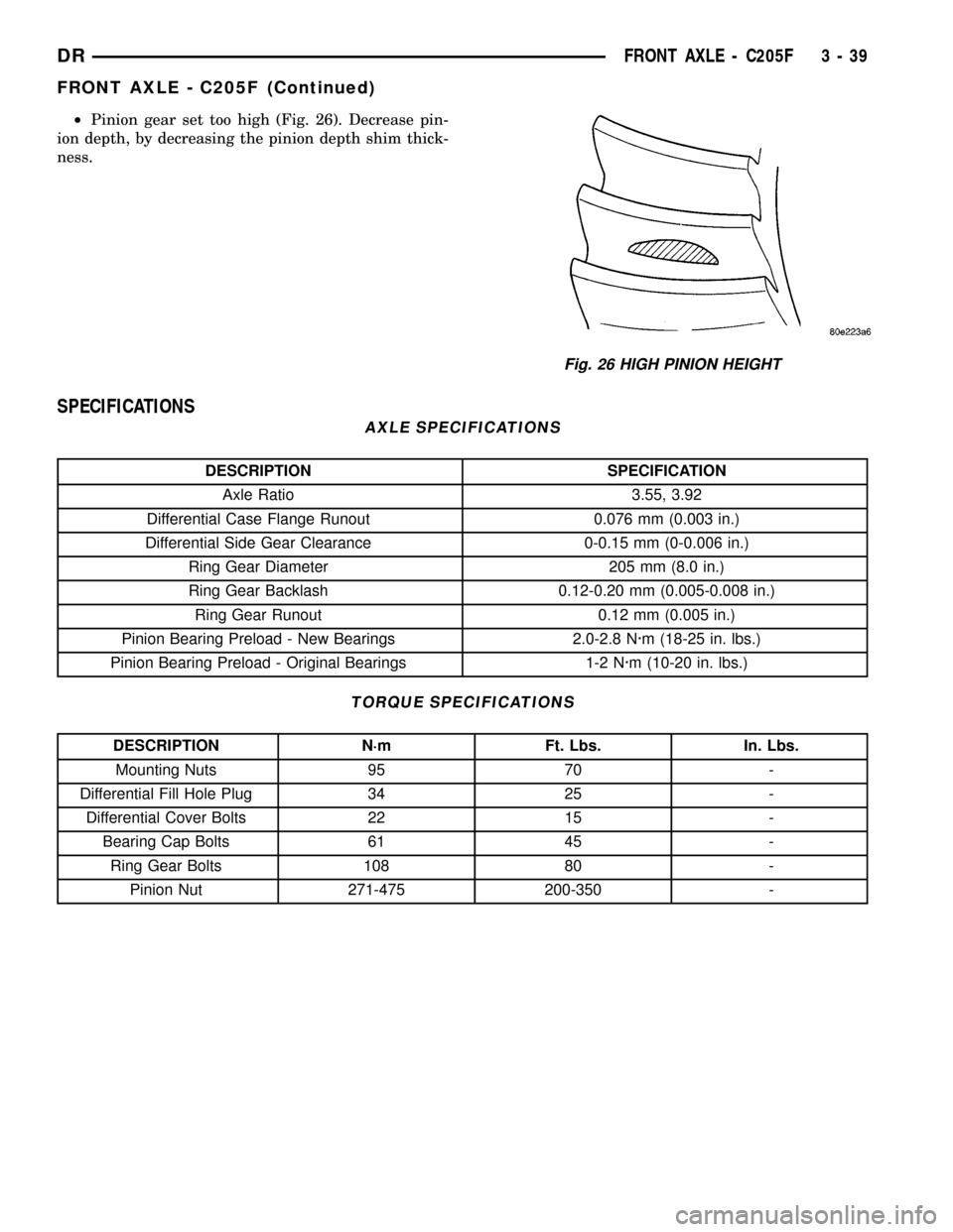
²Pinion gear set too high (Fig. 26). Decrease pin-
ion depth, by decreasing the pinion depth shim thick-
ness.
SPECIFICATIONS
AXLE SPECIFICATIONS
DESCRIPTION SPECIFICATION
Axle Ratio 3.55, 3.92
Differential Case Flange Runout 0.076 mm (0.003 in.)
Differential Side Gear Clearance 0-0.15 mm (0-0.006 in.)
Ring Gear Diameter 205 mm (8.0 in.)
Ring Gear Backlash 0.12-0.20 mm (0.005-0.008 in.)
Ring Gear Runout 0.12 mm (0.005 in.)
Pinion Bearing Preload - New Bearings 2.0-2.8 N´m (18-25 in. lbs.)
Pinion Bearing Preload - Original Bearings 1-2 N´m (10-20 in. lbs.)
TORQUE SPECIFICATIONS
DESCRIPTION N´m Ft. Lbs. In. Lbs.
Mounting Nuts 95 70 -
Differential Fill Hole Plug 34 25 -
Differential Cover Bolts 22 15 -
Bearing Cap Bolts 61 45 -
Ring Gear Bolts 108 80 -
Pinion Nut 271-475 200-350 -
Fig. 26 HIGH PINION HEIGHT
DRFRONT AXLE - C205F 3 - 39
FRONT AXLE - C205F (Continued)
Page 124 of 2627
AXLE SHAFTS
REMOVAL
(1) Remove half shaft from vehicle.
(2) Remove skid plate, if equipped.
(3) Clean axle seal area.
(4) Remove snap ring from the axle shaft.
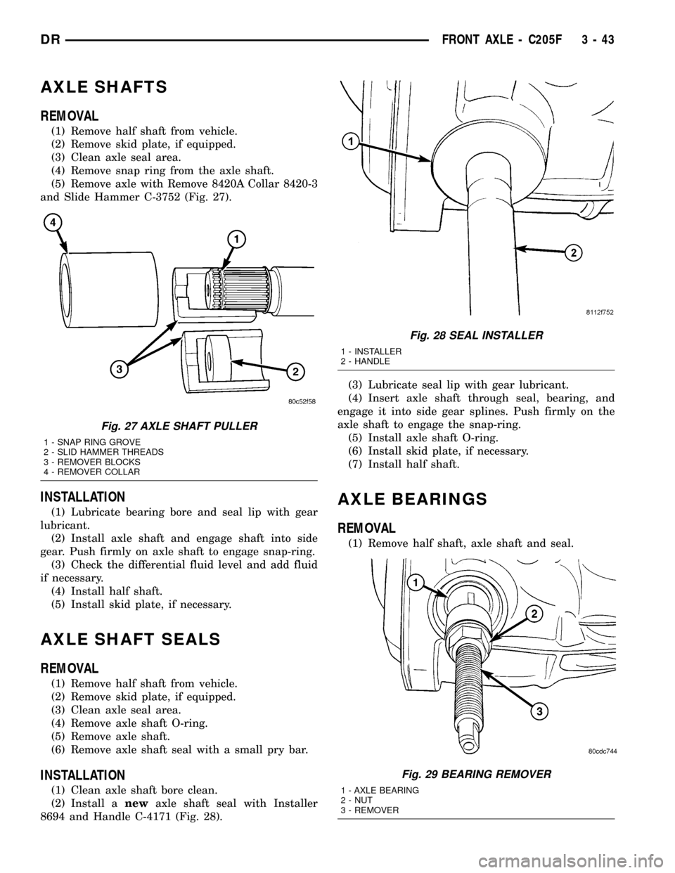
(5) Remove axle with Remove 8420A Collar 8420-3
and Slide Hammer C-3752 (Fig. 27).
INSTALLATION
(1) Lubricate bearing bore and seal lip with gear
lubricant.
(2) Install axle shaft and engage shaft into side
gear. Push firmly on axle shaft to engage snap-ring.
(3) Check the differential fluid level and add fluid
if necessary.
(4) Install half shaft.
(5) Install skid plate, if necessary.
AXLE SHAFT SEALS
REMOVAL
(1) Remove half shaft from vehicle.
(2) Remove skid plate, if equipped.
(3) Clean axle seal area.
(4) Remove axle shaft O-ring.
(5) Remove axle shaft.
(6) Remove axle shaft seal with a small pry bar.
INSTALLATION
(1) Clean axle shaft bore clean.
(2) Install anewaxle shaft seal with Installer
8694 and Handle C-4171 (Fig. 28).(3) Lubricate seal lip with gear lubricant.
(4) Insert axle shaft through seal, bearing, and
engage it into side gear splines. Push firmly on the
axle shaft to engage the snap-ring.
(5) Install axle shaft O-ring.
(6) Install skid plate, if necessary.
(7) Install half shaft.
AXLE BEARINGS
REMOVAL
(1) Remove half shaft, axle shaft and seal.
Fig. 27 AXLE SHAFT PULLER
1 - SNAP RING GROVE
2 - SLID HAMMER THREADS
3 - REMOVER BLOCKS
4 - REMOVER COLLAR
Fig. 28 SEAL INSTALLER
1 - INSTALLER
2 - HANDLE
Fig. 29 BEARING REMOVER
1 - AXLE BEARING
2 - NUT
3 - REMOVER
DRFRONT AXLE - C205F 3 - 43
Page 125 of 2627
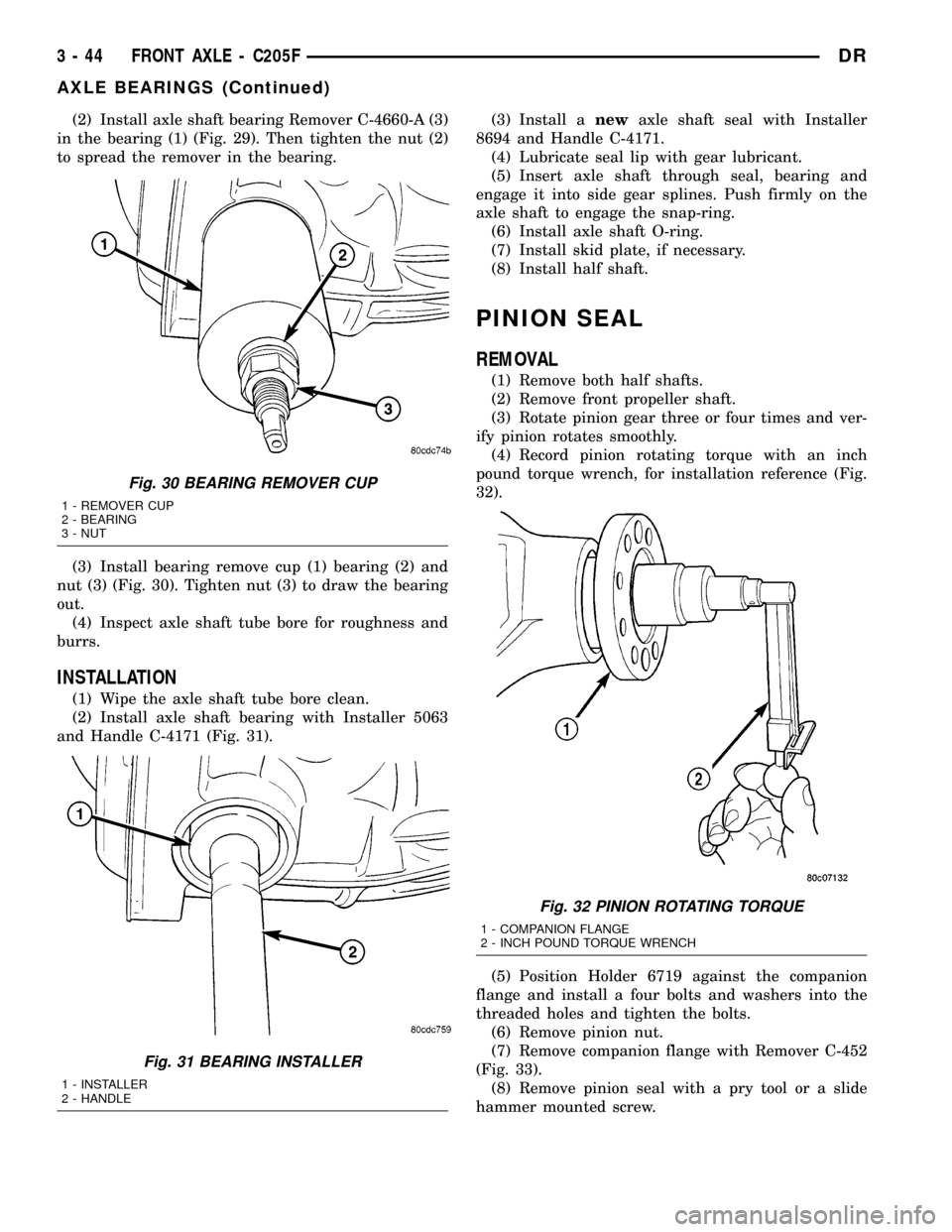
(2) Install axle shaft bearing Remover C-4660-A (3)
in the bearing (1) (Fig. 29). Then tighten the nut (2)
to spread the remover in the bearing.
(3) Install bearing remove cup (1) bearing (2) and
nut (3) (Fig. 30). Tighten nut (3) to draw the bearing
out.
(4) Inspect axle shaft tube bore for roughness and
burrs.
INSTALLATION
(1) Wipe the axle shaft tube bore clean.
(2) Install axle shaft bearing with Installer 5063
and Handle C-4171 (Fig. 31).(3) Install anewaxle shaft seal with Installer
8694 and Handle C-4171.
(4) Lubricate seal lip with gear lubricant.
(5) Insert axle shaft through seal, bearing and
engage it into side gear splines. Push firmly on the
axle shaft to engage the snap-ring.
(6) Install axle shaft O-ring.
(7) Install skid plate, if necessary.
(8) Install half shaft.
PINION SEAL
REMOVAL
(1) Remove both half shafts.
(2) Remove front propeller shaft.
(3) Rotate pinion gear three or four times and ver-
ify pinion rotates smoothly.
(4) Record pinion rotating torque with an inch
pound torque wrench, for installation reference (Fig.
32).
(5) Position Holder 6719 against the companion
flange and install a four bolts and washers into the
threaded holes and tighten the bolts.
(6) Remove pinion nut.
(7) Remove companion flange with Remover C-452
(Fig. 33).
(8) Remove pinion seal with a pry tool or a slide
hammer mounted screw.
Fig. 30 BEARING REMOVER CUP
1 - REMOVER CUP
2 - BEARING
3 - NUT
Fig. 31 BEARING INSTALLER
1 - INSTALLER
2 - HANDLE
Fig. 32 PINION ROTATING TORQUE
1 - COMPANION FLANGE
2 - INCH POUND TORQUE WRENCH
3 - 44 FRONT AXLE - C205FDR
AXLE BEARINGS (Continued)
Page 126 of 2627
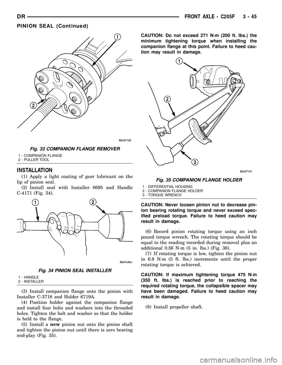
INSTALLATION
(1) Apply a light coating of gear lubricant on the
lip of pinion seal.
(2) Install seal with Installer 8695 and Handle
C-4171 (Fig. 34).
(3) Install companion flange onto the pinion with
Installer C-3718 and Holder 6719A.
(4) Position holder against the companion flange
and install four bolts and washers into the threaded
holes. Tighten the bolt and washer so that the holder
is held to the flange.
(5) Install anewpinion nut onto the pinion shaft
and tighten the pinion nut until there is zero bearing
end-play (Fig. 35).CAUTION: Do not exceed 271 N´m (200 ft. lbs.) the
minimum tightening torque when installing the
companion flange at this point. Failure to heed cau-
tion may result in damage.
CAUTION: Never loosen pinion nut to decrease pin-
ion bearing rotating torque and never exceed spec-
ified preload torque. Failure to heed caution may
result in damage.
(6) Record pinion rotating torque using an inch
pound torque wrench. The rotating torque should be
equal to the reading recorded during removal plus an
additional 0.56 N´m (5 in. lbs.) (Fig. 36).
(7) If rotating torque is low, tighten the pinion nut
in 6.8 N´m (5 ft. lbs.) increments until the proper
rotating torque is achieved.
CAUTION: If maximum tightening torque 475 N´m
(350 ft. lbs.) is reached prior to reaching the
required rotating torque, the collapsible spacer may
have been damaged. Failure to heed caution may
result in damage.
(8) Install propeller shaft.
Fig. 33 COMPANION FLANGE REMOVER
1 - COMPANION FLANGE
2 - PULLER TOOL
Fig. 34 PINION SEAL INSTALLER
1 - HANDLE
2 - INSTALLER
Fig. 35 COMPANION FLANGE HOLDER
1 - DIFFERENTIAL HOUSING
2 - COMPANION FLANGE HOLDER
3 - TORQUE WRENCH
DRFRONT AXLE - C205F 3 - 45
PINION SEAL (Continued)
Page 127 of 2627
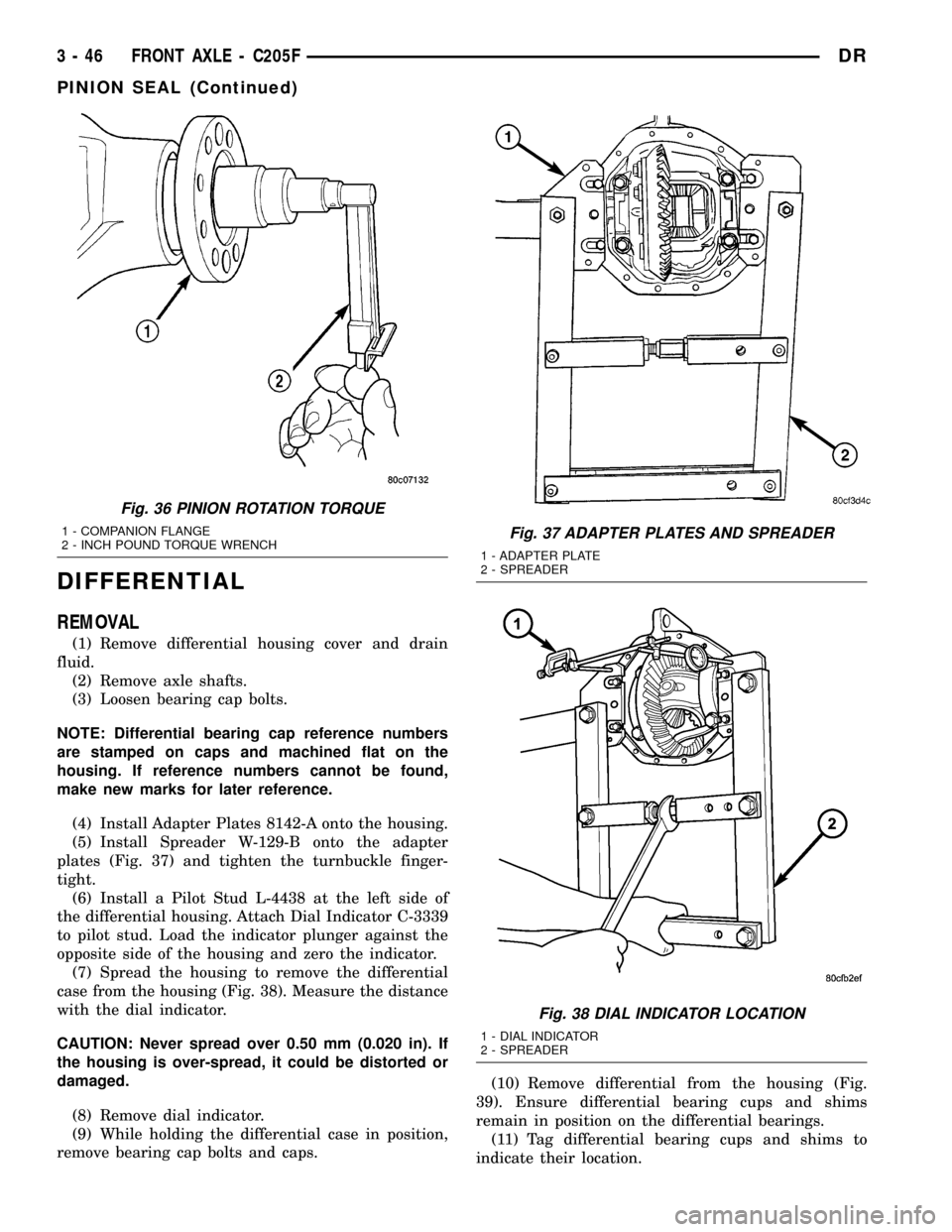
DIFFERENTIAL
REMOVAL
(1) Remove differential housing cover and drain
fluid.
(2) Remove axle shafts.
(3) Loosen bearing cap bolts.
NOTE: Differential bearing cap reference numbers
are stamped on caps and machined flat on the
housing. If reference numbers cannot be found,
make new marks for later reference.
(4) Install Adapter Plates 8142-A onto the housing.
(5) Install Spreader W-129-B onto the adapter
plates (Fig. 37) and tighten the turnbuckle finger-
tight.
(6) Install a Pilot Stud L-4438 at the left side of
the differential housing. Attach Dial Indicator C-3339
to pilot stud. Load the indicator plunger against the
opposite side of the housing and zero the indicator.
(7) Spread the housing to remove the differential
case from the housing (Fig. 38). Measure the distance
with the dial indicator.
CAUTION: Never spread over 0.50 mm (0.020 in). If
the housing is over-spread, it could be distorted or
damaged.
(8) Remove dial indicator.
(9) While holding the differential case in position,
remove bearing cap bolts and caps.(10) Remove differential from the housing (Fig.
39). Ensure differential bearing cups and shims
remain in position on the differential bearings.
(11) Tag differential bearing cups and shims to
indicate their location.
Fig. 36 PINION ROTATION TORQUE
1 - COMPANION FLANGE
2 - INCH POUND TORQUE WRENCHFig. 37 ADAPTER PLATES AND SPREADER
1 - ADAPTER PLATE
2 - SPREADER
Fig. 38 DIAL INDICATOR LOCATION
1 - DIAL INDICATOR
2 - SPREADER
3 - 46 FRONT AXLE - C205FDR
PINION SEAL (Continued)