Locks DODGE RAM 1500 1998 2.G Manual PDF
[x] Cancel search | Manufacturer: DODGE, Model Year: 1998, Model line: RAM 1500, Model: DODGE RAM 1500 1998 2.GPages: 2627
Page 1085 of 2627
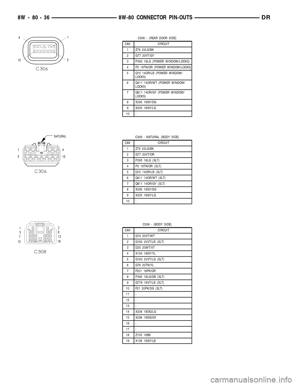
C306 - (REAR DOOR SIDE)
CAV CIRCUIT
1 Z79 20LG/BK
2 G77 20VT/GY
3 P393 18LG (POWER WINDOW/LOCKS)
4 P5 18TN/OR (POWER WINDOW/LOCKS)
5 Q15 14OR/LB (POWER WINDOW/
LOCKS)
6 Q411 14OR/WT (POWER WINDOW/
LOCKS)
7 Q611 14OR/GY (POWER WINDOW/
LOCKS)
8 X295 18GY/DG
9 X205 18GY/LG
10 -
C306 - NATURAL (BODY SIDE)
CAV CIRCUIT
1 Z79 20LG/BK
2 G77 20VT/OR
3 P393 18LG (SLT)
4 P5 18TN/OR (SLT)
5 Q15 14OR/LB (SLT)
6 Q411 14OR/WT (SLT)
7 Q611 14OR/GY (SLT)
8 X295 18GY/DG
9 X205 18GY/LG
10 -
C308 - (BODY SIDE)
CAV CIRCUIT
1 G74 20VT/WT
2 G162 20VT/LB (SLT)
3 D25 20WT/VT
4 X154 18GY/YL
5 G160 20VT/LG (SLT)
6 G76 20TN/YL
7 F201 18PK/OR
8 P392 18LG/DB (SLT)
9 G778 18VT/LB (SLT)
10 F21 20PK/DG (SLT)
11 -
12 -
13 -
14 X206 18DG/LG
15 X296 18DG/GY
16 -
17 -
18 Z105 18BK
19 X156 18GY/LB
8W - 80 - 36 8W-80 CONNECTOR PIN-OUTSDR
Page 1089 of 2627
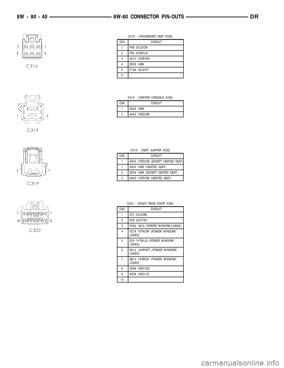
C316 - (PASSENGER SEAT SIDE)
CAV CIRCUIT
1 P89 20LG/OR
2 P54 20OR/LG
3 A210 12OR/RD
4 Z939 14BK
5 P188 18LG/VT
6-
C319 - (CENTER CONSOLE SIDE)
CAV CIRCUIT
1 Z939 18BK
2 A405 18RD/DB
C319 - (SEAT JUMPER SIDE)
CAV CIRCUIT
1 A405 12RD/DB (EXCEPT HEATED SEAT)
1 Z939 14BK (HEATED SEAT)
2 Z939 14BK (EXCEPT HEATED SEAT)
2 A405 12RD/DB (HEATED SEAT)
C320 - (RIGHT REAR DOOR SIDE)
CAV CIRCUIT
1 Z72 20LG/BK
2 G76 20VT/GY
3 P392 18LG (POWER WINDOW/LOCKS)
4 G778 18TN/OR (POWER WINDOW/
LOCKS)
5 Q15 14TN/LG (POWER WINDOW/
LOCKS)
6 Q412 14OR/WT (POWER WINDOW/
LOCKS)
7 Q612 14OR/GY (POWER WINDOW/
LOCKS)
8 X296 18GY/DG
9 X206 18GY/LG
10 -
8W - 80 - 40 8W-80 CONNECTOR PIN-OUTSDR
Page 1095 of 2627
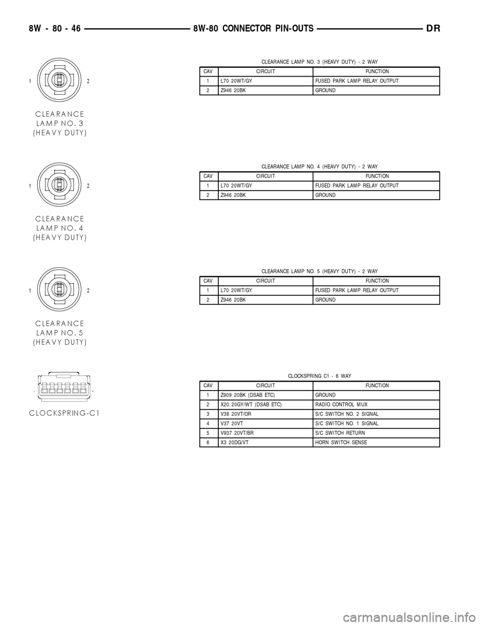
CLEARANCE LAMP NO. 3 (HEAVY DUTY)-2WAY
CAV CIRCUIT FUNCTION
1 L70 20WT/GY FUSED PARK LAMP RELAY OUTPUT
2 Z946 20BK GROUND
CLEARANCE LAMP NO. 4 (HEAVY DUTY)-2WAY
CAV CIRCUIT FUNCTION
1 L70 20WT/GY FUSED PARK LAMP RELAY OUTPUT
2 Z946 20BK GROUND
CLEARANCE LAMP NO. 5 (HEAVY DUTY)-2WAY
CAV CIRCUIT FUNCTION
1 L70 20WT/GY FUSED PARK LAMP RELAY OUTPUT
2 Z946 20BK GROUND
CLOCKSPRING C1-6WAY
CAV CIRCUIT FUNCTION
1 Z909 20BK (DSAB ETC) GROUND
2 X20 20GY/WT (DSAB ETC) RADIO CONTROL MUX
3 V38 20VT/OR S/C SWITCH NO. 2 SIGNAL
4 V37 20VT S/C SWITCH NO. 1 SIGNAL
5 V937 20VT/BR S/C SWITCH RETURN
6 X3 20DG/VT HORN SWITCH SENSE
8W - 80 - 46 8W-80 CONNECTOR PIN-OUTSDR
Page 1096 of 2627
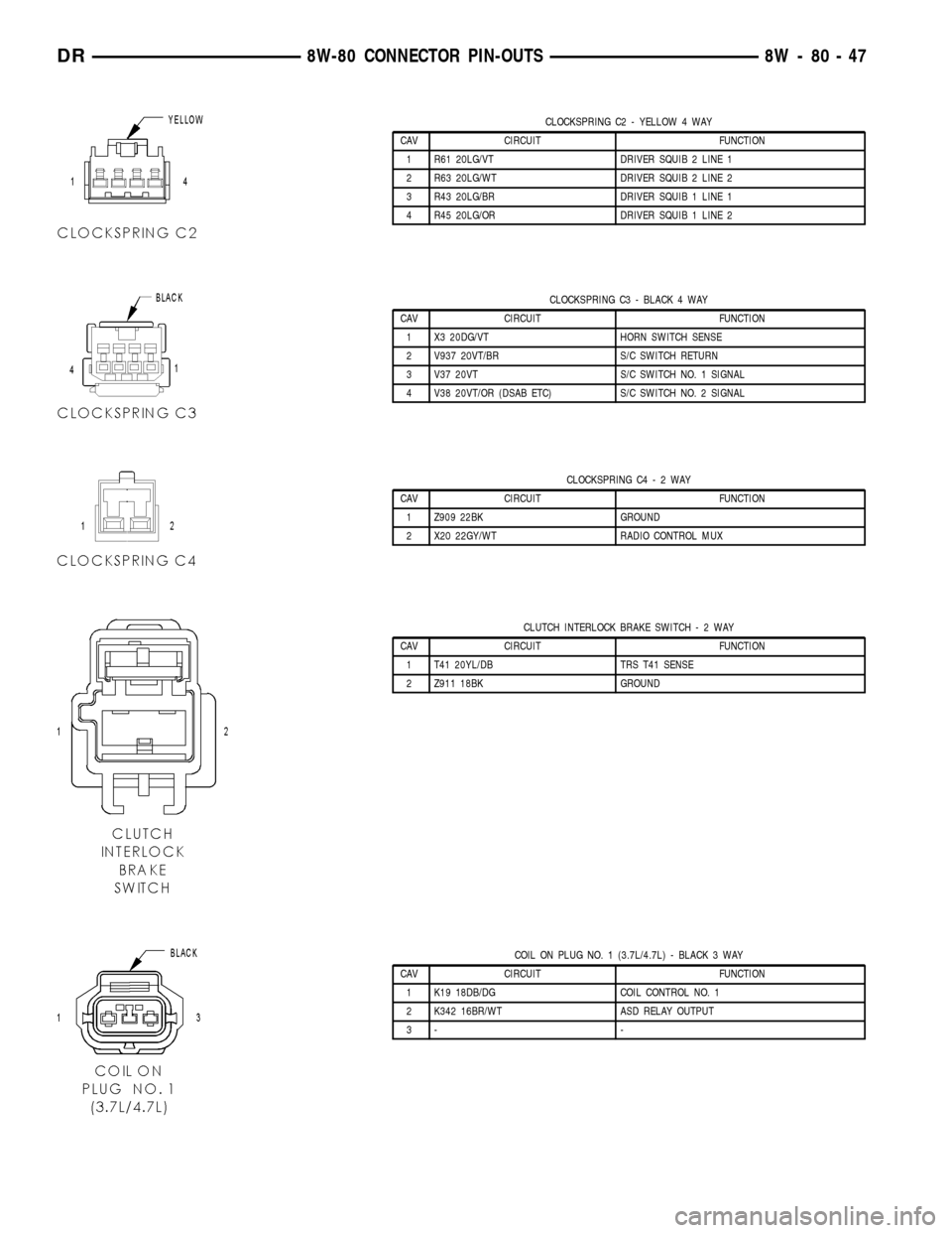
CLOCKSPRING C2 - YELLOW 4 WAY
CAV CIRCUIT FUNCTION
1 R61 20LG/VT DRIVER SQUIB 2 LINE 1
2 R63 20LG/WT DRIVER SQUIB 2 LINE 2
3 R43 20LG/BR DRIVER SQUIB 1 LINE 1
4 R45 20LG/OR DRIVER SQUIB 1 LINE 2
CLOCKSPRING C3 - BLACK 4 WAY
CAV CIRCUIT FUNCTION
1 X3 20DG/VT HORN SWITCH SENSE
2 V937 20VT/BR S/C SWITCH RETURN
3 V37 20VT S/C SWITCH NO. 1 SIGNAL
4 V38 20VT/OR (DSAB ETC) S/C SWITCH NO. 2 SIGNAL
CLOCKSPRING C4-2WAY
CAV CIRCUIT FUNCTION
1 Z909 22BK GROUND
2 X20 22GY/WT RADIO CONTROL MUX
CLUTCH INTERLOCK BRAKE SWITCH-2WAY
CAV CIRCUIT FUNCTION
1 T41 20YL/DB TRS T41 SENSE
2 Z911 18BK GROUND
COIL ON PLUG NO. 1 (3.7L/4.7L) - BLACK 3 WAY
CAV CIRCUIT FUNCTION
1 K19 18DB/DG COIL CONTROL NO. 1
2 K342 16BR/WT ASD RELAY OUTPUT
3- -
DR8W-80 CONNECTOR PIN-OUTS 8W - 80 - 47
Page 1156 of 2627
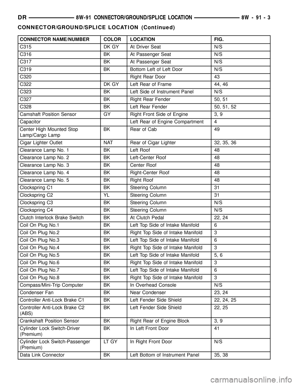
CONNECTOR NAME/NUMBER COLOR LOCATION FIG.
C315 DK GY At Driver Seat N/S
C316 BK At Passenger Seat N/S
C317 BK At Passenger Seat N/S
C319 BK Bottom Left of Left Door N/S
C320 Right Rear Door 43
C322 DK GY Left Rear of Frame 44, 46
C323 BK Left Side of Instrument Panel N/S
C327 BK Right Rear Fender 50, 51
C328 BK Left Rear Fender 50, 51, 52
Camshaft Position Sensor GY Right Front Side of Engine 3, 9
Capacitor Left Rear of Engine Compartment 4
Center High Mounted Stop
Lamp/Cargo LampBK Rear of Cab 49
Cigar Lighter Outlet NAT Rear of Cigar Lighter 32, 35, 36
Clearance Lamp No. 1 BK Left Roof 48
Clearance Lamp No. 2 BK Left-Center Roof 48
Clearance Lamp No. 3 BK Center Roof 48
Clearance Lamp No. 4 BK Right-Center Roof 48
Clearance Lamp No. 5 BK Right Roof 48
Clockspring C1 BK Steering Column 31
Clockspring C2 YL Steering Column 31
Clockspring C3 BK Steering Column N/S
Clockspring C4 BK Steering Column N/S
Clutch Interlock Brake Switch BK At Clutch Pedal 22, 24
Coil On Plug No.1 BK Left Top Side of Intake Manifold 6
Coil On Plug No.2 BK Right Top Side of Intake Manifold 3
Coil On Plug No.3 BK Left Top Side of Intake Manifold 6
Coil On Plug No.4 BK Right Top Side of Intake Manifold 3
Coil On Plug No.5 BK Left Top Side of Intake Manifold 5, 6
Coil On Plug No.6 BK Right Top Side of Intake Manifold 3
Coil On Plug No.7 BK Left Top Side of Intake Manifold 6
Coil On Plug No.8 BK Right Top Side of Intake Manifold 3
Compass/Mini-Trip Computer BK In Overhead Console N/S
Condenser Fan BK Near Condenser 23, 24
Controller Anti-Lock Brake C1 BK Left Fender Side Shield 22, 24, 25
Controller Anti-Lock Brake C2
(ABS)BK Left Fender Side Shield 22, 25
Crankshaft Position Sensor BK Right Rear of Engine Block 3, 9
Cylinder Lock Switch-Driver
(Premium)BK In Left Front Door 41
Cylinder Lock Switch-Passenger
(Premium)LT GY In Right Front Door N/S
Data Link Connector BK Left Bottom of Instrument Panel 35, 38
DR8W-91 CONNECTOR/GROUND/SPLICE LOCATION 8W - 91 - 3
CONNECTOR/GROUND/SPLICE LOCATION (Continued)
Page 1252 of 2627

(5) The valve seat and valve face must maintain a
face angle of 44.5 - 45 É angle (Fig. 17).
REMOVAL
NOTE: The cylinder heads must be removed in
order to perform this procedure.
(1) Remove rocker arms and lash adjusters(Refer
to 9 - ENGINE/CYLINDER HEAD/ROCKER ARM /
ADJUSTER ASSY - REMOVAL). (Fig. 18).
(2) Remove the camshaft bearing caps and the
camshaft.
NOTE: All six valve springs and valves are removed
in the same manner; this procedure only covers
one valve and valve spring.
(3) Using Special Tool C-3422±B or C-3422±C
Valve Spring Compressor and Special tool 8519
Adapter, compress the valve spring.NOTE: It may be necessary to tap the top of the
valve spring to loosen the spring retainers locks
enough to be removed.
(4) Remove the two spring retainer lock halves.
NOTE: the valve spring is under tension use care
when releasing the valve spring compressor.
(5) Remove the valve spring compressor.
(6) Remove the spring retainer, and the spring.
NOTE: Check for sharp edges on the keeper
grooves. Remove any burrs from the valve stem
before removing the valve from the cylinder head.
(7) Remove the valve from the cylinder head.
NOTE: The valve stem seals are common between
intake and exhaust.
(8) Remove the valve stem seal. Mark the valve for
proper installation.
Fig. 17 Valve Assembly Configuration
1 - VALVE LOCKS (3±BEAD)
2 - RETAINER
3 - VALVE STEM OIL SEAL
4 - INTAKE VALVE
5 - EXHAUST VALVE
6 - VALVE SPRING
Fig. 18 Rocker Arm Removal
1 - CAMSHAFT
2 - SPECIAL TOOL 8516
DRENGINE - 3.7L 9 - 29
INTAKE/EXHAUST VALVES & SEATS (Continued)
Page 1253 of 2627

TESTING VALVE SPRINGS
NOTE: Whenever the valves are removed from the
cylinder head it is recommended that the valve
springs be inspected and tested for reuse.
Inspect the valve springs for physical signs of wear or
damage. Turn table of tool C-647 until surface is in line
with the 40.12 mm (1.579 in.) mark on the threaded
stud and the zero mark on the front. Place spring over
the stud on the table and lift compressing lever to set
tone device. Pull on torque wrench until a Ping is
heard. Take reading on torque wrench at this instant.
Multiply this reading by two. This will give the spring
load at test length. Fractional measurements are indi-
cated on the table for finer adjustments. Refer to Spec-
ifications Section to obtain specified height and
allowable tensions. Replace any springs that do not
meet specifications (Fig. 19).
INSTALLATION
(1) coat the valve stem with clean engine oil and
insert it into the cylinder head.
(2) Install the valve stem seal. make sure the seal
is fully seated and that the garter spring at the top
of the seal is intact.
(3) Install the spring and the spring retainer (Fig.
20).
(4) Using the valve spring compressor, compress
the spring and install the two valve spring retainer
halves.
(5) Release the valve spring compressor and make
sure the two spring retainer halves and the spring
retainer are fully seated.
(6) lubricate the camshaft journal with clean
engine oil then Position the camshaft (with the
sprocket dowel on the left camshaft at 11 o'clock and
the right camshaft at 12 o'clock), then position the
camshaft bearing caps.(7) Install the camshaft bearing cap retaining
bolts. Tighten the bolts 9-13 N´m (100 in. lbs.) in 1/2
turn increments in the sequence shown (Fig. 21).
(8)
Position the hydraulic lash adjusters and rocker
arms(Refer to 9 - ENGINE/CYLINDER HEAD/ROCKER
ARM / ADJUSTER ASSY - INSTALLATION).
Fig. 19 Testing Valve Springs
1 - SPECIAL TOOL C-647
Fig. 20 Valve Assembly Configuration
1 - VALVE LOCKS (3±BEAD)
2 - RETAINER
3 - VALVE STEM OIL SEAL
4 - INTAKE VALVE
5 - EXHAUST VALVE
6 - VALVE SPRING
Fig. 21 Camshaft Bearing Caps Tightening
Sequence
9 - 30 ENGINE - 3.7LDR
INTAKE/EXHAUST VALVES & SEATS (Continued)
Page 1255 of 2627

VALVE GUIDE SEALS
DESCRIPTION
The valve guide seals are made of rubber and
incorporate an integral steel valve spring seat. The
integral garter spring maintains consistent lubrica-
tion control to the valve stems.
VALVE SPRINGS
DESCRIPTION
The valve springs are made from high strength
chrome silicon steel. The springs are NOT common
for intake and exhaust applications. The exhaust
spring has an external damper. The valve spring seat
is integral with the valve stem seal, which is a posi-
tive type seal to control lubrication.
REMOVAL
(1) Remove the cylinder head cover(Refer to 9 -
ENGINE/CYLINDER HEAD/CYLINDER HEAD
COVER(S) - REMOVAL).
(2) Using Special Tool 8516 Valve Spring Compres-
sor, remove the rocker arms and the hydraulic lash
adjusters.
(3) Remove the spark plug for the cylinder the
valve spring and seal are to be removed from.
(4) Apply shop air to the cylinder to hold the
valves in place when the spring is removed.
NOTE: All six valve springs and seals are removed
in the same manner; this procedure only covers
one valve seal and valve spring.
(5) Using Special Tool 8387 Valve Spring Compres-
sor, compress the valve spring.
NOTE: It may be necessary to tap the top of the
valve spring to loosen the spring retainers locks
enough to be removed.
(6) Remove the two spring retainer lock halves.
NOTE: the valve spring is under tension use care
when releasing the valve spring compressor.
(7) Remove the valve spring compressor.
NOTE: The valve springs are NOT common between
intake and exhaust.
(8) Remove the spring retainer, and the spring.
(9) Remove the valve stem seal.
NOTE: The valve stem seals are common between
intake and exhaust.
INSTALLATION
NOTE: All six valve springs and seals are removed
in the same manner; this procedure only covers
one valve seal and valve spring.
(1) Apply shop air to the cylinder to hold the
valves in place while the spring is installed.
NOTE: The valve stem seals are common between
intake and exhaust.
(2) Install the valve stem seal.
NOTE: The valve springs are NOT common between
intake and exhaust.
(3) Install the spring retainer, and the spring.
(4) Using Special Tool 8387 Valve Spring Compres-
sor, compress the valve spring.
(5) Install the two spring retainer lock halves.
NOTE: the valve spring is under tension use care
when releasing the valve spring compressor.
(6) Remove the valve spring compressor.
(7) Disconnect the shop air to the cylinder.
(8) Install the spark plug for the cylinder the valve
spring and seal was installed on.
(9) Using Special Tool 8516 Valve Spring Compres-
sor, install the rocker arms and the hydraulic lash
adjusters.
(10) Install the cylinder head cover(Refer to 9 -
ENGINE/CYLINDER HEAD/CYLINDER HEAD
COVER(S) - INSTALLATION).
CYLINDER HEAD - RIGHT
DIAGNOSIS AND TESTING - HYDRAULIC LASH
ADJUSTER
A tappet-like noise may be produced from several
items. Check the following items.
(1) Engine oil level too high or too low. This may
cause aerated oil to enter the adjusters and cause
them to be spongy.
(2) Insufficient running time after rebuilding cylin-
der head. Low speed running up to 1 hour may be
required.
(3) Turn engine off and let set for a few minutes
before restarting. Repeat this several times after
engine has reached normal operating temperature.
(4) Low oil pressure.
(5) The oil restrictor in cylinder head gasket or the
oil passage to the cylinder head is plugged with
debris.
9 - 32 ENGINE - 3.7LDR
Page 1261 of 2627

VALVE GUIDE SEALS
DESCRIPTION
The valve guide seals are made of rubber and
incorporate an integral steel valve spring seat. The
integral garter spring maintains consistent lubrica-
tion control to the valve stems.
VALVE SPRINGS
DESCRIPTION
The valve springs are made from high strength
chrome silicon steel. There are different springs for
intake and exhaust applications. The exhaust spring
has an external damper. The valve spring seat is
integral with the valve stem seal, which is a positive
type seal to control lubrication.
REMOVAL
(1) Remove the cylinder head cover(Refer to 9 -
ENGINE/CYLINDER HEAD/CYLINDER HEAD
COVER(S) - REMOVAL).
(2) Using Special Tool 8516 Valve Spring Compres-
sor, remove the rocker arms and the hydraulic lash
adjusters.
(3) Remove the spark plug for the cylinder the
valve spring and seal are to be removed from.
(4) Apply shop air to the cylinder to hold the
valves in place when the spring is removed.
NOTE: All six valve springs and seals are removed
in the same manner; this procedure only covers
one valve seal and valve spring.
(5) Using Special Tool 8387 Valve Spring Compres-
sor, compress the valve spring.
NOTE: It may be necessary to tap the top of the
valve spring to loosen the spring retainers locks
enough to be removed.
(6) Remove the two spring retainer lock halves.
NOTE: the valve spring is under tension use care
when releasing the valve spring compressor.
(7) Remove the valve spring compressor.
NOTE: The valve springs are NOT common between
intake and exhaust.
(8) Remove the spring retainer, and the spring.
(9) Remove the valve stem seal.
NOTE: The valve stem seals are common between
intake and exhaust.
INSTALLATION
NOTE: All six valve springs and seals are removed
in the same manner; this procedure only covers
one valve seal and valve spring.
(1) Apply shop air to the cylinder to hold the
valves in place while the spring is installed.
NOTE: The valve stem seals are common between
intake and exhaust.
(2) Install the valve stem seal.
NOTE: The valve springs are NOT common between
intake and exhaust.
(3) Install the spring retainer, and the spring.
(4) Using Special Tool 8387 Valve Spring Compres-
sor, compress the valve spring.
(5) Install the two spring retainer lock halves.
NOTE: the valve spring is under tension use care
when releasing the valve spring compressor.
(6) Remove the valve spring compressor.
(7) Disconnect the shop air to the cylinder.
(8) Install the spark plug for the cylinder the valve
spring and seal was installed on.
(9) Using Special Tool 8516 Valve Spring Compres-
sor, install the rocker arms and the hydraulic lash
adjusters.
(10) Install the cylinder head cover(Refer to 9 -
ENGINE/CYLINDER HEAD/CYLINDER HEAD
COVER(S) - INSTALLATION).
ENGINE BLOCK
DESCRIPTION
The cylinder block is made of cast iron. The block
is a closed deck design with the left bank forward. To
provide high rigidity and improved NVH an
enhanced compacted graphite bedplate is bolted to
the block. The block design allows coolant flow
between the cylinders bores, and an internal coolant
bypass to a single poppet inlet thermostat is included
in the cast aluminum front cover.
STANDARD PROCEDURE - CYLINDER BORE
HONING
Before honing, stuff plenty of clean shop towels
under the bores and over the crankshaft to keep
abrasive materials from entering the crankshaft
area.
(1) Used carefully, the Cylinder Bore Sizing Hone
C-823, equipped with 220 grit stones, is the best tool
9 - 38 ENGINE - 3.7LDR
Page 1347 of 2627

REMOVAL
NOTE: The cylinder heads must be removed in
order to perform this procedure.
(1) Remove rocker arms and lash adjusters(Refer
to 9 - ENGINE/CYLINDER HEAD/ROCKER ARM /
ADJUSTER ASSY - REMOVAL). (Fig. 41).
(2) Remove the camshaft bearing caps and the
camshaft.
NOTE: All six valve springs and valves are removed
in the same manner; this procedure only covers
one valve and valve spring.
(3) Using Special Tool C-3422±B or C-3422±C
Valve Spring Compressor and Special tool 8519
Adapter, compress the valve spring.
NOTE: It may be necessary to tap the top of the
valve spring to loosen the spring retainers locks
enough to be removed.
(4) Remove the two spring retainer lock halves.
NOTE: the valve spring is under tension use care
when releasing the valve spring compressor.
(5) Remove the valve spring compressor.
(6) Remove the spring retainer, and the spring.NOTE: Check for sharp edges on the keeper
grooves. Remove any burrs from the valve stem
before removing the valve from the cylinder head.
(7) Remove the valve from the cylinder head.
NOTE: The valve stem seals are common between
intake and exhaust.
(8) Remove the valve stem seal. Mark the valve for
proper installation.
TESTING VALVE SPRINGS
NOTE: Whenever the valves are removed from the
cylinder head it is recommended that the valve
springs be inspected and tested for reuse.
Inspect the valve springs for physical signs of wear
or damage. Turn table of tool C-647 until surface is
in line with the 40.12 mm (1.579 in.) mark on the
threaded stud and the zero mark on the front. Place
spring over the stud on the table and lift compress-
ing lever to set tone device. Pull on torque wrench
until a Ping is heard. Take reading on torque wrench
at this instant. Multiply this reading by two. This
will give the spring load at test length. Fractional
measurements are indicated on the table for finer
adjustments. Refer to Specifications Section to obtain
specified height and allowable tensions. Replace any
springs that do not meet specifications (Fig. 42).
INSTALLATION
(1) coat the valve stem with clean engine oil and
insert it into the cylinder head.
(2) Install the valve stem seal. make sure the seal
is fully seated and that the garter spring at the top
of the seal is intact.
Fig. 41 Rocker Arm Removal
1 - CAMSHAFT
2 - SPECIAL TOOL 8516
Fig. 42 Testing Valve Springs
1 - SPECIAL TOOL C-647
9 - 124 ENGINE - 4.7LDR
INTAKE/EXHAUST VALVES & SEATS (Continued)