One DODGE RAM 1500 1998 2.G Workshop Manual
[x] Cancel search | Manufacturer: DODGE, Model Year: 1998, Model line: RAM 1500, Model: DODGE RAM 1500 1998 2.GPages: 2627
Page 2152 of 2627

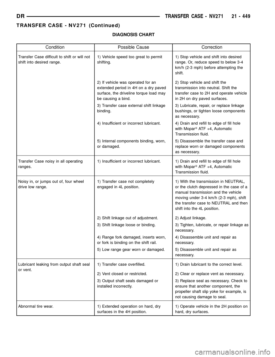
DIAGNOSIS CHART
Condition Possible Cause Correction
Transfer Case difficult to shift or will not
shift into desired range.1) Vehicle speed too great to permit
shifting.1) Stop vehicle and shift into desired
range. Or, reduce speed to below 3-4
km/h (2-3 mph) before attempting the
shift.
2) If vehicle was operated for an
extended period in 4H on a dry paved
surface, the driveline torque load may
be causing a bind.2) Stop vehicle and shift the
transmission into neutral. Shift the
transfer case to 2H and operate vehicle
in 2H on dry paved surfaces.
3) Transfer case external shift linkage
binding.3) Lubricate, repair, or replace linkage
bushings, or tighten loose components
as necessary.
4) Insufficient or incorrect lubricant. 4) Drain and refill to edge of fill hole
with MoparTATF +4, Automatic
Transmission fluid.
5) Internal components binding, worn,
or damaged.5) Disassemble the transfer case and
replace worn or damaged components
as necessary.
Transfer Case noisy in all operating
ranges.1) Insufficient or incorrect lubricant. 1) Drain and refill to edge of fill hole
with MoparTATF +4, Automatic
Transmission fluid.
Noisy in, or jumps out of, four wheel
drive low range.1) Transfer case not completely
engaged in 4L position.1) With the transmission in NEUTRAL,
or the clutch depressed in the case of a
manual transmission and the vehicle
moving under 3-4 km/h (2-3 mph), shift
the transfer case to NEUTRAL and then
shift into the 4L position.
2) Shift linkage out of adjustment. 2) Adjust linkage.
3) Shift linkage loose or binding. 3) Tighten, lubricate, or repair linkage as
necessary.
4) Range fork damaged, inserts worn,
or fork is binding on the shift rail.4) Disassemble unit and repair as
necessary.
5) Low range gear worn or damaged. 5) Disassemble unit and repair as
necessary.
Lubricant leaking from output shaft seal
or vent.1) Transfer case overfilled. 1) Drain lubricant to the correct level.
2) Vent closed or restricted. 2) Clear or replace vent as necessary.
3) Output shaft seals damaged or
installed incorrectly.3) Replace seal as necessary. Check to
ensure that another component, the
propeller shaft slip yoke for example, is
not causing damage to seal.
Abnormal tire wear. 1) Extended operation on hard, dry
surfaces in the 4H position.1) Operate vehicle in the 2H position on
hard, dry surfaces.
DRTRANSFER CASE - NV271 21 - 449
TRANSFER CASE - NV271 (Continued)
Page 2162 of 2627

(6) Remove front thrust plate (Fig. 37).
(7) Remove input gear (Fig. 38).
(8) Remove bottom tabbed thrust washer from low
range planetary (Fig. 39).
CLEANING
Clean the transfer case parts with a standard
parts cleaning solvent. Remove all traces of sealer
from the cases and retainers with a scraper and
3MŸ all purpose cleaner. Use compressed air toremove solvent residue from oil feed passages in the
case halves, retainers, gears, and shafts.
INSPECTION
MAINSHAFT/SPROCKET/HUB
Inspect the splines on the hub and shaft and the
teeth on the sprocket. Minor nicks and scratches can
be smoothed with an oilstone, however, replace any
part that is damaged.
Check the contact surfaces in the sprocket bore
and on the mainshaft. Minor nicks and scratches can
be smoothed with 320-400 grit emery cloth but do not
try to salvage the shaft if nicks or wear is severe.
INPUT GEAR AND PLANETARY CARRIER
Check the teeth on the gear (Fig. 40). Minor nicks
can be dressed off with an oilstone but replace the
gear if any teeth are broken, cracked, or chipped. The
bearing surface on the gear can be smoothed with
300-400 grit emery cloth if necessary.
Examine the carrier body and pinion gears for
wear or damage. Check the pinion gear thrust wash-
ers on the pinon pins for damage. The carrier will
have to be replaced as an assembly if the body, pin-
ion pins, or pinion gears are damaged.
Check the lock ring and both thrust washers for
wear or cracks. Replace them if necessary. Also
replace the lock retaining ring if bent, distorted, or
broken.
Fig. 37 Remove Input Gear Thrust Plate
1 - INPUT GEAR
2 - THRUST PLATE
Fig. 38 Remove Input Gear From Planetary
1 - INPUT GEAR
2 - LOW RANGE PLANETARY
Fig. 39 Remove Bottom Input Gear Thrust Plate
1 - PLANETARY
2 - THRUST PLATE
DRTRANSFER CASE - NV271 21 - 459
TRANSFER CASE - NV271 (Continued)
Page 2163 of 2627

SHIFT FORKS/HUBS/SLEEVES
Check condition of the shift forks and mode fork
shift rail (Fig. 41). Minor nicks on the shift rail can
be smoothed with 320-400 grit emery cloth.Inspect the shift fork wear pads (Fig. 42). The
mode and range fork pads are serviceable and can be
replaced if necessary.
Check both of the sleeves for wear or damage,
especially on the interior teeth. Replace the sleeves if
wear or damage is evident.
Fig. 40 Input Gear And Carrier Components
1 - PLANETARY CARRIER 4 - CARRIER LOCK RING
2 - REAR THRUST WASHER 5 - CARRIER LOCK RETAINING RING
3 - FRONT THRUST WASHER 6 - INPUT GEAR
Fig. 41 Shift forks
1 - RANGE FORK
2 - MODE FORK AND RAIL
3 - MODE SPRING
Fig. 42 Shift Fork And Wear Pad Locations
1 - RANGE FORK
2 - MODE FORK
3 - WEAR PADS (SERVICEABLE)
4 - WEAR PADS (SERVICEABLE)
21 - 460 TRANSFER CASE - NV271DR
TRANSFER CASE - NV271 (Continued)
Page 2172 of 2627

(17) Install detent plunger, spring, and plug (Fig.
74). Tighten the plug to 16-25 N´m (12-18 ft. lbs.).
FRONT OUTPUT SHAFT AND DRIVE CHAIN
(1) Install the front output shaft (Fig. 75) into the
front output shaft front bearing.
(2) Install the front output shaft bearing inner
snap-ring (Fig. 76) onto the output shaft.
(3) Install the new front output shaft seal with
Installer MB991168A
(4) Insert front drive sprocket in drive chain.
(5) Install drive chain around rear drive sprocket.(6) Position rear drive sprocket (Fig. 77) over the
output shaft and lower the sprocket and chain
assembly until the front sprocket is positioned over
the front output shaft.
(7) Align the splines in the sprockets to the splines
on the output shafts and install the sprockets onto
the output shafts.
Fig. 74 Install Detent plug, Spring, and Plunger
1 - FRONT CASE HALF
2 - DETENT PLUG
3 - SPRING
4 - PLUNGER
Fig. 75 Install Front Output Shaft
1 - FRONT CASE
2 - FRONT OUTPUT SHAFT
Fig. 76 Install Front Output Shaft Bearing Inner
Snap-Ring
1 - FRONT CASE HALF
2 - SNAP-RING
Fig. 77 Install Drive Chain and Sprockets
1 - FRONT CASE HALF
2 - CHAIN
3 - DRIVE SPROCKETS
DRTRANSFER CASE - NV271 21 - 469
TRANSFER CASE - NV271 (Continued)
Page 2186 of 2627

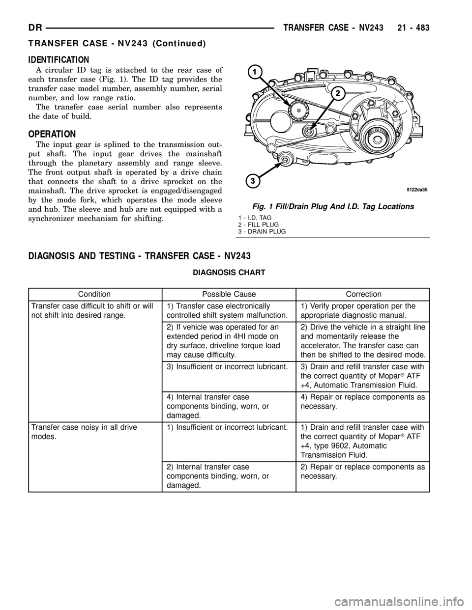
IDENTIFICATION
A circular ID tag is attached to the rear case of
each transfer case (Fig. 1). The ID tag provides the
transfer case model number, assembly number, serial
number, and low range ratio.
The transfer case serial number also represents
the date of build.
OPERATION
The input gear is splined to the transmission out-
put shaft. The input gear drives the mainshaft
through the planetary assembly and range sleeve.
The front output shaft is operated by a drive chain
that connects the shaft to a drive sprocket on the
mainshaft. The drive sprocket is engaged/disengaged
by the mode fork, which operates the mode sleeve
and hub. The sleeve and hub are not equipped with a
synchronizer mechanism for shifting.
DIAGNOSIS AND TESTING - TRANSFER CASE - NV243
DIAGNOSIS CHART
Condition Possible Cause Correction
Transfer case difficult to shift or will
not shift into desired range.1) Transfer case electronically
controlled shift system malfunction.1) Verify proper operation per the
appropriate diagnostic manual.
2) If vehicle was operated for an
extended period in 4HI mode on
dry surface, driveline torque load
may cause difficulty.2) Drive the vehicle in a straight line
and momentarily release the
accelerator. The transfer case can
then be shifted to the desired mode.
3) Insufficient or incorrect lubricant. 3) Drain and refill transfer case with
the correct quantity of MoparTAT F
+4, Automatic Transmission Fluid.
4) Internal transfer case
components binding, worn, or
damaged.4) Repair or replace components as
necessary.
Transfer case noisy in all drive
modes.1) Insufficient or incorrect lubricant. 1) Drain and refill transfer case with
the correct quantity of MoparTAT F
+4, type 9602, Automatic
Transmission Fluid.
2) Internal transfer case
components binding, worn, or
damaged.2) Repair or replace components as
necessary.
Fig. 1 Fill/Drain Plug And I.D. Tag Locations
1 - I.D. TAG
2 - FILL PLUG
3 - DRAIN PLUG
DRTRANSFER CASE - NV243 21 - 483
TRANSFER CASE - NV243 (Continued)
Page 2187 of 2627

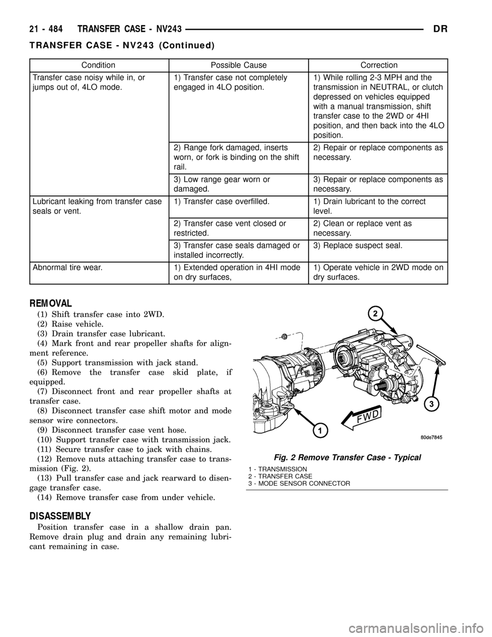
Condition Possible Cause Correction
Transfer case noisy while in, or
jumps out of, 4LO mode.1) Transfer case not completely
engaged in 4LO position.1) While rolling 2-3 MPH and the
transmission in NEUTRAL, or clutch
depressed on vehicles equipped
with a manual transmission, shift
transfer case to the 2WD or 4HI
position, and then back into the 4LO
position.
2) Range fork damaged, inserts
worn, or fork is binding on the shift
rail.2) Repair or replace components as
necessary.
3) Low range gear worn or
damaged.3) Repair or replace components as
necessary.
Lubricant leaking from transfer case
seals or vent.1) Transfer case overfilled. 1) Drain lubricant to the correct
level.
2) Transfer case vent closed or
restricted.2) Clean or replace vent as
necessary.
3) Transfer case seals damaged or
installed incorrectly.3) Replace suspect seal.
Abnormal tire wear. 1) Extended operation in 4HI mode
on dry surfaces,1) Operate vehicle in 2WD mode on
dry surfaces.
REMOVAL
(1) Shift transfer case into 2WD.
(2) Raise vehicle.
(3) Drain transfer case lubricant.
(4) Mark front and rear propeller shafts for align-
ment reference.
(5) Support transmission with jack stand.
(6) Remove the transfer case skid plate, if
equipped.
(7) Disconnect front and rear propeller shafts at
transfer case.
(8) Disconnect transfer case shift motor and mode
sensor wire connectors.
(9) Disconnect transfer case vent hose.
(10) Support transfer case with transmission jack.
(11) Secure transfer case to jack with chains.
(12) Remove nuts attaching transfer case to trans-
mission (Fig. 2).
(13) Pull transfer case and jack rearward to disen-
gage transfer case.
(14) Remove transfer case from under vehicle.
DISASSEMBLY
Position transfer case in a shallow drain pan.
Remove drain plug and drain any remaining lubri-
cant remaining in case.
Fig. 2 Remove Transfer Case - Typical
1 - TRANSMISSION
2 - TRANSFER CASE
3 - MODE SENSOR CONNECTOR
21 - 484 TRANSFER CASE - NV243DR
TRANSFER CASE - NV243 (Continued)
Page 2196 of 2627

(2) Remove retainer (Fig. 35).
(3) Remove front tabbed thrust washer (Fig. 36).
(4) Remove input gear (Fig. 37).
(5) Remove rear tabbed thrust washer from low
range gear (Fig. 38).
CLEANING
Clean the transfer case parts with a standard
parts cleaning solvent. Remove all traces of sealer
from the cases and retainers with a scraper and
3MŸ all purpose cleaner. Use compressed air to
remove solvent residue from oil feed passages in the
case halves, retainers, gears, and shafts.
INSPECTION
MAINSHAFT/SPROCKET/HUB INSPECTION
Inspect the splines on the hub and shaft and the
teeth on the sprocket. Minor nicks and scratches can
be smoothed with an oilstone. However, replace any
part that is damaged.
Check the contact surfaces in the sprocket bore
and on the mainshaft. Minor nicks and scratches can
be smoothed with 320-400 grit emery cloth but do not
try to salvage the shaft if nicks or wear is severe.
Fig. 35 Input Gear Retainer Removal
1 - INPUT GEAR
2 - LOW RANGE GEAR
3 - RETAINER
Fig. 36 Front Tabbed Thrust Washer Removal
1 - FRONT TABBED THRUST WASHER
Fig. 37 Input Gear Removal
1 - INPUT GEAR
2 - LOW RANGE GEAR
Fig. 38 Rear Tabbed Thrust Washer Removal
1 - LOW RANGE GEAR
2 - REAR TABBED THRUST WASHER
DRTRANSFER CASE - NV243 21 - 493
TRANSFER CASE - NV243 (Continued)
Page 2197 of 2627

INPUT GEAR AND PLANETARY CARRIER
Check the teeth on the gear (Fig. 39). Minor nicks
can be dressed off with an oilstone but replace the
gear if any teeth are broken, cracked, or chipped. The
bearing surface on the gear can be smoothed with
300-400 grit emery cloth if necessary.
Examine the carrier body and pinion gears for
wear or damage. The carrier will have to be replaced
as an assembly if the body, pinion pins, or pinion
gears are damaged.
Check the lock ring and both thrust washers for
wear or cracks. Replace them if necessary. Also
replace the lock retaining ring if bent, distorted, or
broken.
SHIFT FORKS/HUBS/SLEEVES
Check condition of the shift forks and mode fork
shift rail (Fig. 40). Minor nicks on the shift rail can
be smoothed with 320-400 grit emery cloth.
Fig. 39 Input Gear and Carrier Components
1 - PLANETARY CARRIER 4 - CARRIER LOCK RING
2 - REAR THRUST WASHER 5 - CARRIER LOCK RETAINING RING
3 - FRONT THRUST WASHER 6 - INPUT GEAR
Fig. 40 Shift Forks
1 - RANGE FORK
2 - MODE FORK AND RAIL
3 - MODE SPRING
21 - 494 TRANSFER CASE - NV243DR
TRANSFER CASE - NV243 (Continued)
Page 2198 of 2627

Inspect the shift fork wear pads (Fig. 41). The
mode and range fork pads are serviceable and can be
replaced if necessary.
Check both of the sleeves for wear or damage,
especially on the interior teeth. Replace the sleeves if
wear or damage is evident.
REAR EXTENSION HOUSING
Inspect the extension housing seal and bushing.
Replace both components if either show any sign of
wear or damage.
FRONT OUTPUT SHAFT AND DRIVE CHAIN
Inspect the shaft threads, sprocket teeth, and bear-
ing surfaces. Minor nicks on the teeth can be
smoothed with an oilstone. Use 320-400 grit emery to
smooth minor scratches on the shaft bearing sur-
faces. Rough threads on the shaft can be chased if
necessary. Replace the shaft if the threads are dam-
aged, bearing surfaces are scored, or if any sprocket
teeth are cracked or broken.
Examine the drive chain and shaft bearings.
Replace the chain and both sprockets if the chain is
stretched, distorted, or if any of the links bind.
Replace the bearings if rough, or noisy.
LOW RANGE ANNULUS GEAR
Inspect annulus gear condition carefully. The gear
is only serviced as part of the front case. If the gear
is damaged, it will be necessary to replace the gear
and front case as an assembly. Do not attempt to
remove the gear (Fig. 42)
FRONT AND REAR CASES
Inspect the cases for wear and damage.
Check case condition. If leaks were a problem, look
for gouges and severe scoring of case sealing sur-
faces. Also make sure the front case mounting studs
are in good condition.
Check the front case mounting studs and vent
tube. The tube can be secured with LoctiteŸ 271 or
680 if loose. The stud threads can be cleaned up with
a die if necessary. Also check condition of the fill/
drain plug threads in the rear case. The threads can
be repaired with a thread chaser or tap if necessary.
Or the threads can be repaired with Helicoiltstain-
less steel inserts if required.
OIL PUMP/OIL PICKUP
Examine the oil pump pickup parts. Replace the
pump if any part appears to be worn or damaged. Do
not disassemble the pump as individual parts are not
available. The pump is only available as a complete
assembly. The pickup screen, hose, and tube are the
only serviceable parts and are available separately.
Fig. 41 Shift Fork And Wear Pad Locations
1 - RANGE FORK
2 - MODE FORK
3 - WEAR PADS (SERVICEABLE)
4 - WEAR PADS (SERVICEABLE)
Fig. 42 Low Range Annulus Gear
1 - FRONT CASE
2 - LOW RANGE ANNULUS GEAR
DRTRANSFER CASE - NV243 21 - 495
TRANSFER CASE - NV243 (Continued)
Page 2201 of 2627

(10) Remove the rear output shaft bearing from
the rear case using Remover/Installer 8684 and Han-
dle C-4171 (Fig. 49).
(11) Install the rear output shaft bearing (Fig. 50)
into the rear case using Remover/Installer 6953 and
Handle C-4171.INPUT AND PLANETARY GEAR
(1) Lubricate gears and thrust washers (Fig. 51)
with recommended transmission fluid.
(2) Install first thrust washer in low range gear
(Fig. 51). Be sure washer tabs are properly aligned in
gear notches.
(3) Install input gear in low range gear. Be sure
input gear is fully seated.
(4) Install remaining thrust washer in low range
gear and on top of input gear. Be sure washer tabs
are properly aligned in gear notches.
(5) Install retainer on input gear and install snap-
ring.
Fig. 49 Remove Rear Output Shaft Bearing
1 - REAR CASE
2 - REMOVER/INSTALLER 8684
3 - HANDLE C-4171
Fig. 50 Install Rear Output Shaft Bearing
1 - REAR CASE
2 - REMOVER/INSTALLER 6953
3 - HANDLE C-4171
Fig. 51 Input/Low Range Gear Components
1 - SNAP-RING
2 - RETAINER PLATE
3 - INPUT GEAR
4 - LOW RANGE GEAR
5 - THRUST WASHERS
21 - 498 TRANSFER CASE - NV243DR
TRANSFER CASE - NV243 (Continued)