Causes DODGE RAM 1500 1998 2.G Workshop Manual
[x] Cancel search | Manufacturer: DODGE, Model Year: 1998, Model line: RAM 1500, Model: DODGE RAM 1500 1998 2.GPages: 2627
Page 37 of 2627
OPERATION
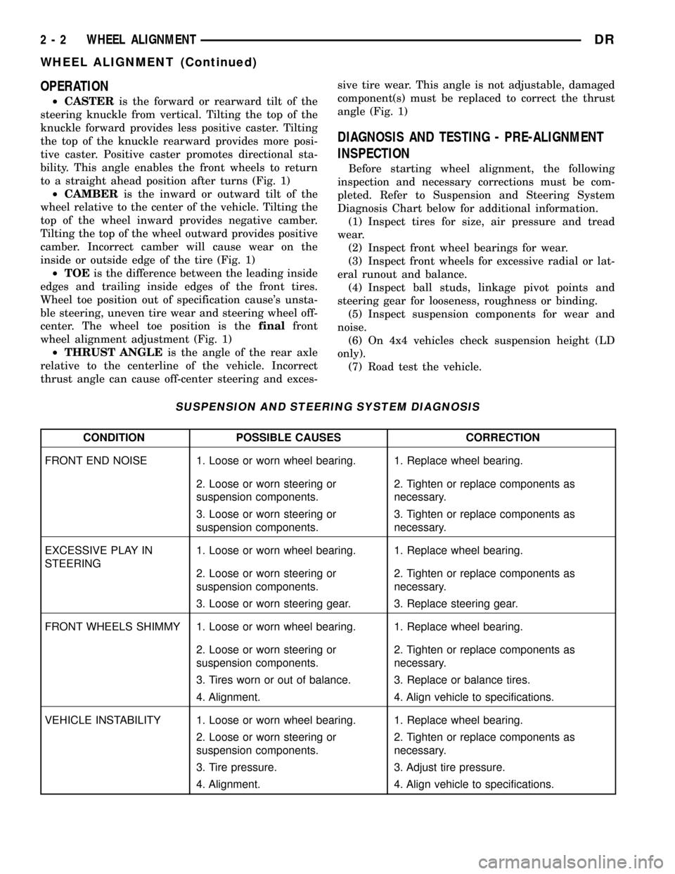
²CASTERis the forward or rearward tilt of the
steering knuckle from vertical. Tilting the top of the
knuckle forward provides less positive caster. Tilting
the top of the knuckle rearward provides more posi-
tive caster. Positive caster promotes directional sta-
bility. This angle enables the front wheels to return
to a straight ahead position after turns (Fig. 1)
²CAMBERis the inward or outward tilt of the
wheel relative to the center of the vehicle. Tilting the
top of the wheel inward provides negative camber.
Tilting the top of the wheel outward provides positive
camber. Incorrect camber will cause wear on the
inside or outside edge of the tire (Fig. 1)
²TOEis the difference between the leading inside
edges and trailing inside edges of the front tires.
Wheel toe position out of specification cause's unsta-
ble steering, uneven tire wear and steering wheel off-
center. The wheel toe position is thefinalfront
wheel alignment adjustment (Fig. 1)
²THRUST ANGLEis the angle of the rear axle
relative to the centerline of the vehicle. Incorrect
thrust angle can cause off-center steering and exces-sive tire wear. This angle is not adjustable, damaged
component(s) must be replaced to correct the thrust
angle (Fig. 1)
DIAGNOSIS AND TESTING - PRE-ALIGNMENT
INSPECTION
Before starting wheel alignment, the following
inspection and necessary corrections must be com-
pleted. Refer to Suspension and Steering System
Diagnosis Chart below for additional information.
(1) Inspect tires for size, air pressure and tread
wear.
(2) Inspect front wheel bearings for wear.
(3) Inspect front wheels for excessive radial or lat-
eral runout and balance.
(4) Inspect ball studs, linkage pivot points and
steering gear for looseness, roughness or binding.
(5) Inspect suspension components for wear and
noise.
(6) On 4x4 vehicles check suspension height (LD
only).
(7) Road test the vehicle.
SUSPENSION AND STEERING SYSTEM DIAGNOSIS
CONDITION POSSIBLE CAUSES CORRECTION
FRONT END NOISE 1. Loose or worn wheel bearing. 1. Replace wheel bearing.
2. Loose or worn steering or
suspension components.2. Tighten or replace components as
necessary.
3. Loose or worn steering or
suspension components.3. Tighten or replace components as
necessary.
EXCESSIVE PLAY IN
STEERING1. Loose or worn wheel bearing. 1. Replace wheel bearing.
2. Loose or worn steering or
suspension components.2. Tighten or replace components as
necessary.
3. Loose or worn steering gear. 3. Replace steering gear.
FRONT WHEELS SHIMMY 1. Loose or worn wheel bearing. 1. Replace wheel bearing.
2. Loose or worn steering or
suspension components.2. Tighten or replace components as
necessary.
3. Tires worn or out of balance. 3. Replace or balance tires.
4. Alignment. 4. Align vehicle to specifications.
VEHICLE INSTABILITY 1. Loose or worn wheel bearing. 1. Replace wheel bearing.
2. Loose or worn steering or
suspension components.2. Tighten or replace components as
necessary.
3. Tire pressure. 3. Adjust tire pressure.
4. Alignment. 4. Align vehicle to specifications.
2 - 2 WHEEL ALIGNMENTDR
WHEEL ALIGNMENT (Continued)
Page 38 of 2627
CONDITION POSSIBLE CAUSES CORRECTION
EXCESSIVE STEERING
EFFORT1. Loose or worn steering gear. 1. Replace steering gear.
2. Column coupler binding. 2. Replace coupler.
3. Tire pressure. 3. Adjust tire pressure.
4. Alignment. 4. Align vehicle to specifications.
VEHICLE PULLS TO ONE
SIDE1. Tire pressure. 1. Adjust tire pressure.
2. Tire. 2. Criss-Cross Front Tires.
3. Alignment. 3. Align vehicle to specifications.
4. Loose or worn steering or
suspension components.4. Tighten or replace components as
necessary.
5. Radial tire lead. 5. Rotate or replace tire as necessary.
6. Brake pull. 6. Repair brake as necessary.
7. Weak or broken spring. 7. Replace spring.
8. Ride height (LD) 4WD only. 8. Measure and adjust ride height. (LD
only)
STANDARD PROCEDURE
STANDARD PROCEDURE - HEIGHT
MEASUREMENT - 4WD (LD)
The vehicle suspension height MUST be measured
and adjusted before performing wheel alignment pro-
cedure. Also when front suspension components have
been replaced. This measure must be performed with
the vehicle supporting it's own weight and taken on
both sides of the vehicle.
(1) Inspect tires and set to correct pressure.
(2) Jounce the front of the vehicle.
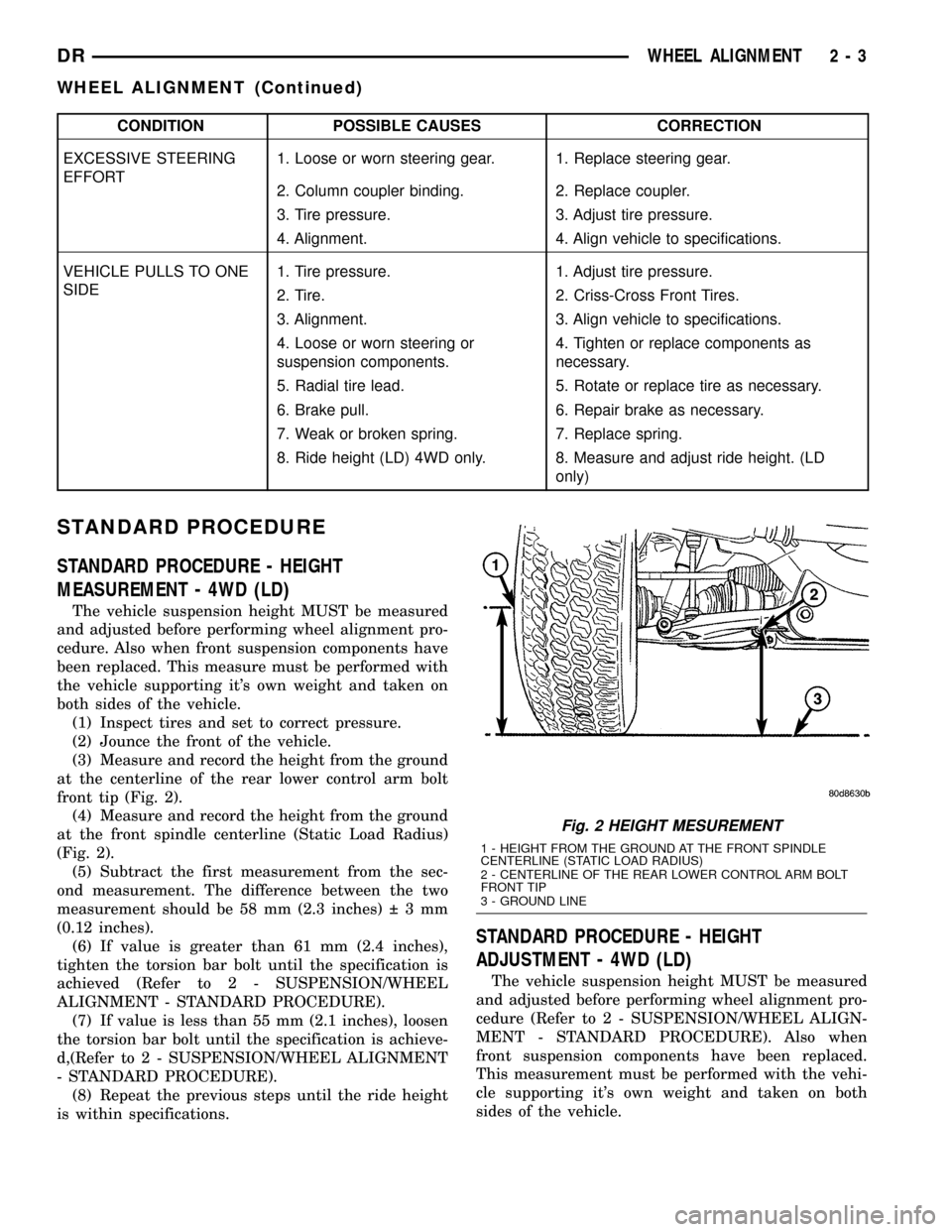
(3) Measure and record the height from the ground
at the centerline of the rear lower control arm bolt
front tip (Fig. 2).
(4) Measure and record the height from the ground
at the front spindle centerline (Static Load Radius)
(Fig. 2).
(5) Subtract the first measurement from the sec-
ond measurement. The difference between the two
measurement should be 58 mm (2.3 inches) 3mm
(0.12 inches).
(6) If value is greater than 61 mm (2.4 inches),
tighten the torsion bar bolt until the specification is
achieved (Refer to 2 - SUSPENSION/WHEEL
ALIGNMENT - STANDARD PROCEDURE).
(7) If value is less than 55 mm (2.1 inches), loosen
the torsion bar bolt until the specification is achieve-
d,(Refer to 2 - SUSPENSION/WHEEL ALIGNMENT
- STANDARD PROCEDURE).
(8) Repeat the previous steps until the ride height
is within specifications.
STANDARD PROCEDURE - HEIGHT
ADJUSTMENT - 4WD (LD)
The vehicle suspension height MUST be measured
and adjusted before performing wheel alignment pro-
cedure (Refer to 2 - SUSPENSION/WHEEL ALIGN-
MENT - STANDARD PROCEDURE). Also when
front suspension components have been replaced.
This measurement must be performed with the vehi-
cle supporting it's own weight and taken on both
sides of the vehicle.
Fig. 2 HEIGHT MESUREMENT
1 - HEIGHT FROM THE GROUND AT THE FRONT SPINDLE
CENTERLINE (STATIC LOAD RADIUS)
2 - CENTERLINE OF THE REAR LOWER CONTROL ARM BOLT
FRONT TIP
3 - GROUND LINE
DRWHEEL ALIGNMENT 2 - 3
WHEEL ALIGNMENT (Continued)
Page 77 of 2627
SPRING AND SHOCK ABSORBER
CONDITION POSSIBLE CAUSES CORRECTION
SPRING SAGS 1. Broken leaf. 1. Replace spring.
2. Spring fatigue. 2. Replace spring.
SPRING NOISE 1. Loose spring clamp bolts. 1. Tighten to specification.
2. Worn bushings. 2. Replace bushings.
3. Worn or missing spring tip inserts. 3. Replace spring tip inserts.
SHOCK NOISE 1. Loose mounting fastener. 1. Tighten to specification.
2. Worn bushings. 2. Replace shock.
3. Leaking shock. 3. Replace shock.
SPECIFICATIONS
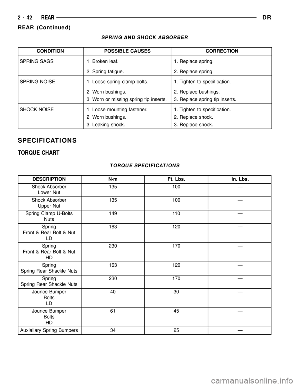
TORQUE CHART
TORQUE SPECIFICATIONS
DESCRIPTION N´m Ft. Lbs. In. Lbs.
Shock Absorber
Lower Nut135 100 Ð
Shock Absorber
Upper Nut135 100 Ð
Spring Clamp U-Bolts
Nuts149 110 Ð
Spring
Front & Rear Bolt & Nut
LD163 120 Ð
Spring
Front & Rear Bolt & Nut
HD230 170 Ð
Spring
Spring Rear Shackle Nuts163 120 Ð
Spring
Spring Rear Shackle Nuts230 170 Ð
Jounce Bumper
Bolts
LD40 30 Ð
Jounce Bumper
Bolts
HD61 45 Ð
Auxialiary Spring Bumpers 34 25 Ð
2 - 42 REARDR
REAR (Continued)
Page 84 of 2627
(10) Start engine and check vibration. If there is
little or no change move the clamp to the next posi-
tions. Repeat the vibration test.
NOTE: If there is no difference in vibration at this
positions, the vibration may not be the propeller
shaft.
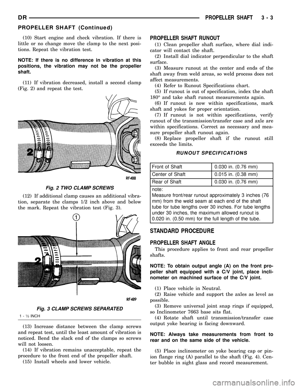
(11) If vibration decreased, install a second clamp
(Fig. 2) and repeat the test.
(12) If additional clamp causes an additional vibra-
tion, separate the clamps 1/2 inch above and below
the mark. Repeat the vibration test (Fig. 3).
(13) Increase distance between the clamp screws
and repeat test, until the least amount of vibration is
noticed. Bend the slack end of the clamps so screws
will not loosen.
(14) If vibration remains unacceptable, repeat the
procedure to the front end of the propeller shaft.
(15) Install wheels and lower vehicle.PROPELLER SHAFT RUNOUT
(1) Clean propeller shaft surface, where dial indi-
cator will contact the shaft.
(2) Install dial indicator perpendicular to the shaft
surface.
(3) Measure runout at the center and ends of the
shaft away from weld areas, so weld process does not
affect measurements.
(4) Refer to Runout Specifications chart.
(5) If runout is out of specification, index the shaft
180É and take shaft runout measurements again.
(6) If runout is now within specifications, mark
shaft and yokes for proper orientation.
(7) If runout is not within specifications, verify
runout of the transmission/transfer case and axle are
within specifications. Correct as necessary and mea-
sure propeller shaft runout again.
(8) Replace propeller shaft if the runout still
exceeds the limits.
RUNOUT SPECIFICATIONS
Front of Shaft 0.030 in. (0.76 mm)
Center of Shaft 0.015 in. (0.38 mm)
Rear of Shaft 0.030 in. (0.76 mm)
note:
Measure front/rear runout approximately 3 inches (76
mm) from the weld seam at each end of the shaft
tube for tube lengths over 30 inches. For tube lengths
under 30 inches, the maximum allowed runout is
0.020 in. (0.50 mm) for the full length of the tube.
STANDARD PROCEDURE
PROPELLER SHAFT ANGLE
This procedure applies to front and rear propeller
shafts.
NOTE: To obtain output angle (A) on the front pro-
peller shaft equipped with a C/V joint, place incli-
nometer on machined surface of the C/V joint.
(1) Place vehicle in Neutral.
(2) Raise vehicle and support the axles as level as
possible.
(3) Remove universal joint snap rings if equipped,
so Inclinometer 7663 base sits flat.
(4) Rotate shaft until transmission/transfer case
output yoke bearing is facing downward.
NOTE: Always take measurements from front to
rear and on the same side of the vehicle.
(5) Place inclinometer on yoke bearing cap or pin-
ion flange ring (A) parallel to the shaft (Fig. 4). Cen-
ter bubble in sight glass and record measurement.
Fig. 2 TWO CLAMP SCREWS
Fig. 3 CLAMP SCREWS SEPARATED
1-1¤2INCH
DRPROPELLER SHAFT 3 - 3
PROPELLER SHAFT (Continued)
Page 109 of 2627
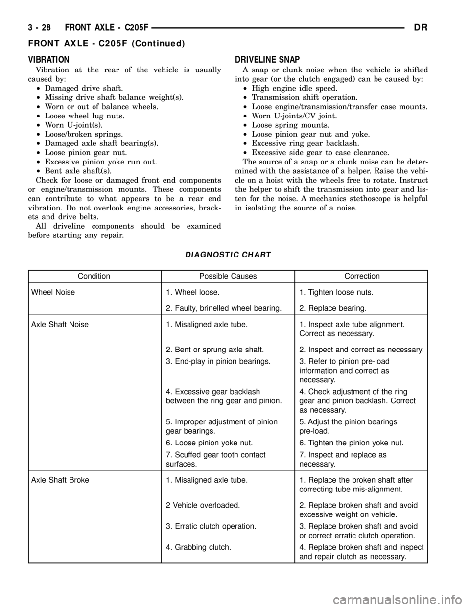
VIBRATION
Vibration at the rear of the vehicle is usually
caused by:
²Damaged drive shaft.
²Missing drive shaft balance weight(s).
²Worn or out of balance wheels.
²Loose wheel lug nuts.
²Worn U-joint(s).
²Loose/broken springs.
²Damaged axle shaft bearing(s).
²Loose pinion gear nut.
²Excessive pinion yoke run out.
²Bent axle shaft(s).
Check for loose or damaged front end components
or engine/transmission mounts. These components
can contribute to what appears to be a rear end
vibration. Do not overlook engine accessories, brack-
ets and drive belts.
All driveline components should be examined
before starting any repair.
DRIVELINE SNAP
A snap or clunk noise when the vehicle is shifted
into gear (or the clutch engaged) can be caused by:
²High engine idle speed.
²Transmission shift operation.
²Loose engine/transmission/transfer case mounts.
²Worn U-joints/CV joint.
²Loose spring mounts.
²Loose pinion gear nut and yoke.
²Excessive ring gear backlash.
²Excessive side gear to case clearance.
The source of a snap or a clunk noise can be deter-
mined with the assistance of a helper. Raise the vehi-
cle on a hoist with the wheels free to rotate. Instruct
the helper to shift the transmission into gear and lis-
ten for the noise. A mechanics stethoscope is helpful
in isolating the source of a noise.
DIAGNOSTIC CHART
Condition Possible Causes Correction
Wheel Noise 1. Wheel loose. 1. Tighten loose nuts.
2. Faulty, brinelled wheel bearing. 2. Replace bearing.
Axle Shaft Noise 1. Misaligned axle tube. 1. Inspect axle tube alignment.
Correct as necessary.
2. Bent or sprung axle shaft. 2. Inspect and correct as necessary.
3. End-play in pinion bearings. 3. Refer to pinion pre-load
information and correct as
necessary.
4. Excessive gear backlash
between the ring gear and pinion.4. Check adjustment of the ring
gear and pinion backlash. Correct
as necessary.
5. Improper adjustment of pinion
gear bearings.5. Adjust the pinion bearings
pre-load.
6. Loose pinion yoke nut. 6. Tighten the pinion yoke nut.
7. Scuffed gear tooth contact
surfaces.7. Inspect and replace as
necessary.
Axle Shaft Broke 1. Misaligned axle tube. 1. Replace the broken shaft after
correcting tube mis-alignment.
2 Vehicle overloaded. 2. Replace broken shaft and avoid
excessive weight on vehicle.
3. Erratic clutch operation. 3. Replace broken shaft and avoid
or correct erratic clutch operation.
4. Grabbing clutch. 4. Replace broken shaft and inspect
and repair clutch as necessary.
3 - 28 FRONT AXLE - C205FDR
FRONT AXLE - C205F (Continued)
Page 110 of 2627
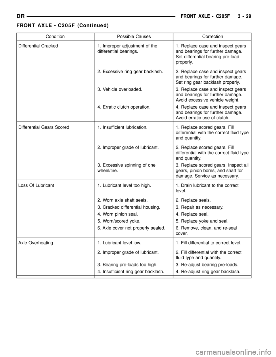
Condition Possible Causes Correction
Differential Cracked 1. Improper adjustment of the
differential bearings.1. Replace case and inspect gears
and bearings for further damage.
Set differential bearing pre-load
properly.
2. Excessive ring gear backlash. 2. Replace case and inspect gears
and bearings for further damage.
Set ring gear backlash properly.
3. Vehicle overloaded. 3. Replace case and inspect gears
and bearings for further damage.
Avoid excessive vehicle weight.
4. Erratic clutch operation. 4. Replace case and inspect gears
and bearings for further damage.
Avoid erratic use of clutch.
Differential Gears Scored 1. Insufficient lubrication. 1. Replace scored gears. Fill
differential with the correct fluid type
and quantity.
2. Improper grade of lubricant. 2. Replace scored gears. Fill
differential with the correct fluid type
and quantity.
3. Excessive spinning of one
wheel/tire.3. Replace scored gears. Inspect all
gears, pinion bores, and shaft for
damage. Service as necessary.
Loss Of Lubricant 1. Lubricant level too high. 1. Drain lubricant to the correct
level.
2. Worn axle shaft seals. 2. Replace seals.
3. Cracked differential housing. 3. Repair as necessary.
4. Worn pinion seal. 4. Replace seal.
5. Worn/scored yoke. 5. Replace yoke and seal.
6. Axle cover not properly sealed. 6. Remove, clean, and re-seal
cover.
Axle Overheating 1. Lubricant level low. 1. Fill differential to correct level.
2. Improper grade of lubricant. 2. Fill differential with the correct
fluid type and quantity.
3. Bearing pre-loads too high. 3. Re-adjust bearing pre-loads.
4. Insufficient ring gear backlash. 4. Re-adjust ring gear backlash.
DRFRONT AXLE - C205F 3 - 29
FRONT AXLE - C205F (Continued)
Page 111 of 2627
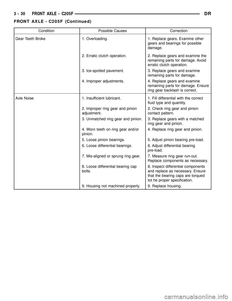
Condition Possible Causes Correction
Gear Teeth Broke 1. Overloading. 1. Replace gears. Examine other
gears and bearings for possible
damage.
2. Erratic clutch operation. 2. Replace gears and examine the
remaining parts for damage. Avoid
erratic clutch operation.
3. Ice-spotted pavement. 3. Replace gears and examine
remaining parts for damage.
4. Improper adjustments. 4. Replace gears and examine
remaining parts for damage. Ensure
ring gear backlash is correct.
Axle Noise 1. Insufficient lubricant. 1. Fill differential with the correct
fluid type and quantity.
2. Improper ring gear and pinion
adjustment.2. Check ring gear and pinion
contact pattern.
3. Unmatched ring gear and pinion. 3. Replace gears with a matched
ring gear and pinion.
4. Worn teeth on ring gear and/or
pinion.4. Replace ring gear and pinion.
5. Loose pinion bearings. 5. Adjust pinion bearing pre-load.
6. Loose differential bearings. 6. Adjust differential bearing
pre-load.
7. Mis-aligned or sprung ring gear. 7. Measure ring gear run-out.
Replace components as necessary.
8. Loose differential bearing cap
bolts.8. Inspect differential components
and replace as necessary. Ensure
that the bearing caps are torqued
tot he proper specification.
9. Housing not machined properly. 9. Replace housing.
3 - 30 FRONT AXLE - C205FDR
FRONT AXLE - C205F (Continued)
Page 136 of 2627
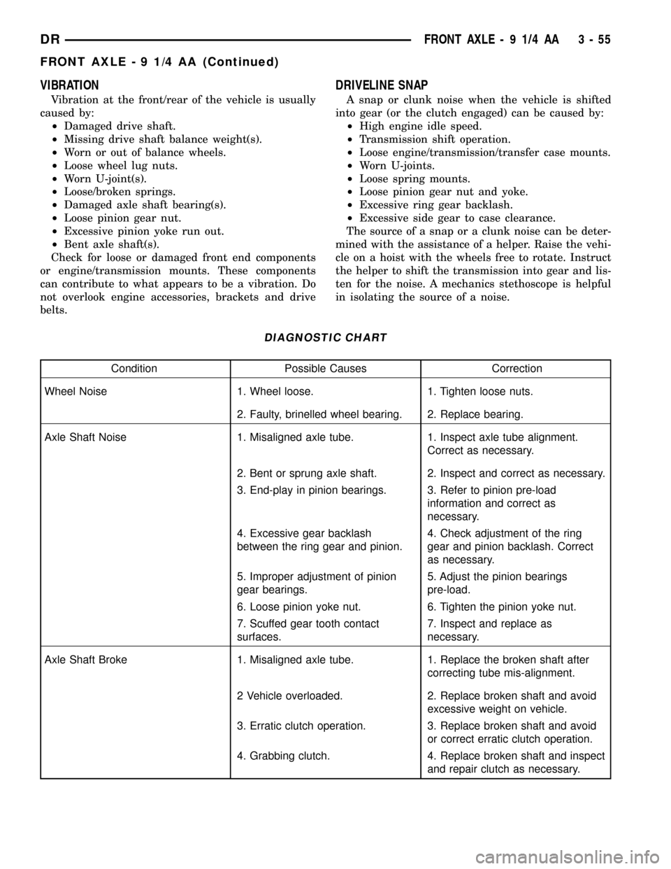
VIBRATION
Vibration at the front/rear of the vehicle is usually
caused by:
²Damaged drive shaft.
²Missing drive shaft balance weight(s).
²Worn or out of balance wheels.
²Loose wheel lug nuts.
²Worn U-joint(s).
²Loose/broken springs.
²Damaged axle shaft bearing(s).
²Loose pinion gear nut.
²Excessive pinion yoke run out.
²Bent axle shaft(s).
Check for loose or damaged front end components
or engine/transmission mounts. These components
can contribute to what appears to be a vibration. Do
not overlook engine accessories, brackets and drive
belts.
DRIVELINE SNAP
A snap or clunk noise when the vehicle is shifted
into gear (or the clutch engaged) can be caused by:
²High engine idle speed.
²Transmission shift operation.
²Loose engine/transmission/transfer case mounts.
²Worn U-joints.
²Loose spring mounts.
²Loose pinion gear nut and yoke.
²Excessive ring gear backlash.
²Excessive side gear to case clearance.
The source of a snap or a clunk noise can be deter-
mined with the assistance of a helper. Raise the vehi-
cle on a hoist with the wheels free to rotate. Instruct
the helper to shift the transmission into gear and lis-
ten for the noise. A mechanics stethoscope is helpful
in isolating the source of a noise.
DIAGNOSTIC CHART
Condition Possible Causes Correction
Wheel Noise 1. Wheel loose. 1. Tighten loose nuts.
2. Faulty, brinelled wheel bearing. 2. Replace bearing.
Axle Shaft Noise 1. Misaligned axle tube. 1. Inspect axle tube alignment.
Correct as necessary.
2. Bent or sprung axle shaft. 2. Inspect and correct as necessary.
3. End-play in pinion bearings. 3. Refer to pinion pre-load
information and correct as
necessary.
4. Excessive gear backlash
between the ring gear and pinion.4. Check adjustment of the ring
gear and pinion backlash. Correct
as necessary.
5. Improper adjustment of pinion
gear bearings.5. Adjust the pinion bearings
pre-load.
6. Loose pinion yoke nut. 6. Tighten the pinion yoke nut.
7. Scuffed gear tooth contact
surfaces.7. Inspect and replace as
necessary.
Axle Shaft Broke 1. Misaligned axle tube. 1. Replace the broken shaft after
correcting tube mis-alignment.
2 Vehicle overloaded. 2. Replace broken shaft and avoid
excessive weight on vehicle.
3. Erratic clutch operation. 3. Replace broken shaft and avoid
or correct erratic clutch operation.
4. Grabbing clutch. 4. Replace broken shaft and inspect
and repair clutch as necessary.
DRFRONT AXLE - 9 1/4 AA 3 - 55
FRONT AXLE - 9 1/4 AA (Continued)
Page 137 of 2627
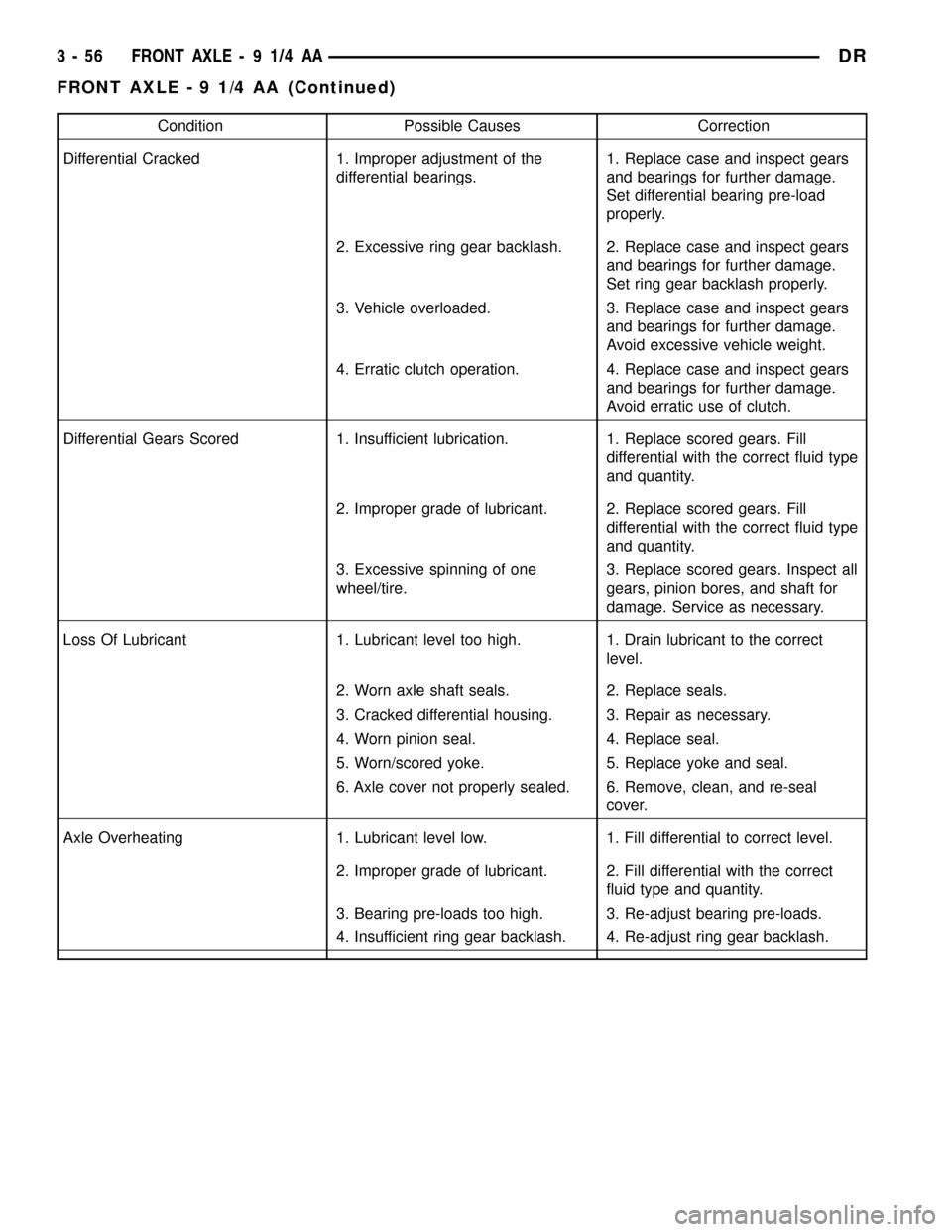
Condition Possible Causes Correction
Differential Cracked 1. Improper adjustment of the
differential bearings.1. Replace case and inspect gears
and bearings for further damage.
Set differential bearing pre-load
properly.
2. Excessive ring gear backlash. 2. Replace case and inspect gears
and bearings for further damage.
Set ring gear backlash properly.
3. Vehicle overloaded. 3. Replace case and inspect gears
and bearings for further damage.
Avoid excessive vehicle weight.
4. Erratic clutch operation. 4. Replace case and inspect gears
and bearings for further damage.
Avoid erratic use of clutch.
Differential Gears Scored 1. Insufficient lubrication. 1. Replace scored gears. Fill
differential with the correct fluid type
and quantity.
2. Improper grade of lubricant. 2. Replace scored gears. Fill
differential with the correct fluid type
and quantity.
3. Excessive spinning of one
wheel/tire.3. Replace scored gears. Inspect all
gears, pinion bores, and shaft for
damage. Service as necessary.
Loss Of Lubricant 1. Lubricant level too high. 1. Drain lubricant to the correct
level.
2. Worn axle shaft seals. 2. Replace seals.
3. Cracked differential housing. 3. Repair as necessary.
4. Worn pinion seal. 4. Replace seal.
5. Worn/scored yoke. 5. Replace yoke and seal.
6. Axle cover not properly sealed. 6. Remove, clean, and re-seal
cover.
Axle Overheating 1. Lubricant level low. 1. Fill differential to correct level.
2. Improper grade of lubricant. 2. Fill differential with the correct
fluid type and quantity.
3. Bearing pre-loads too high. 3. Re-adjust bearing pre-loads.
4. Insufficient ring gear backlash. 4. Re-adjust ring gear backlash.
3 - 56 FRONT AXLE - 9 1/4 AADR
FRONT AXLE - 9 1/4 AA (Continued)
Page 138 of 2627
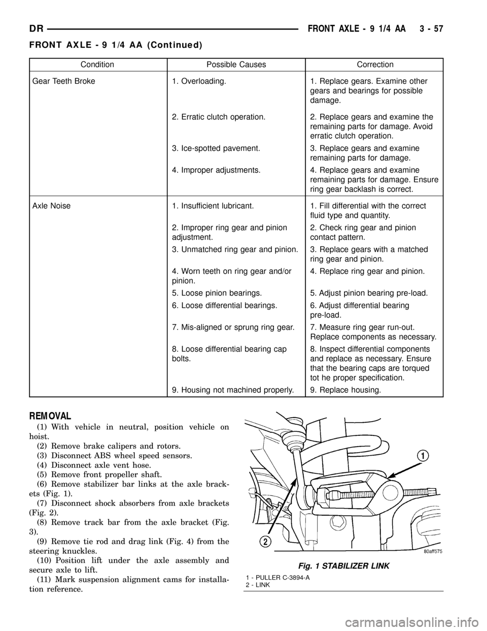
Condition Possible Causes Correction
Gear Teeth Broke 1. Overloading. 1. Replace gears. Examine other
gears and bearings for possible
damage.
2. Erratic clutch operation. 2. Replace gears and examine the
remaining parts for damage. Avoid
erratic clutch operation.
3. Ice-spotted pavement. 3. Replace gears and examine
remaining parts for damage.
4. Improper adjustments. 4. Replace gears and examine
remaining parts for damage. Ensure
ring gear backlash is correct.
Axle Noise 1. Insufficient lubricant. 1. Fill differential with the correct
fluid type and quantity.
2. Improper ring gear and pinion
adjustment.2. Check ring gear and pinion
contact pattern.
3. Unmatched ring gear and pinion. 3. Replace gears with a matched
ring gear and pinion.
4. Worn teeth on ring gear and/or
pinion.4. Replace ring gear and pinion.
5. Loose pinion bearings. 5. Adjust pinion bearing pre-load.
6. Loose differential bearings. 6. Adjust differential bearing
pre-load.
7. Mis-aligned or sprung ring gear. 7. Measure ring gear run-out.
Replace components as necessary.
8. Loose differential bearing cap
bolts.8. Inspect differential components
and replace as necessary. Ensure
that the bearing caps are torqued
tot he proper specification.
9. Housing not machined properly. 9. Replace housing.
REMOVAL
(1) With vehicle in neutral, position vehicle on
hoist.
(2) Remove brake calipers and rotors.
(3) Disconnect ABS wheel speed sensors.
(4) Disconnect axle vent hose.
(5) Remove front propeller shaft.
(6) Remove stabilizer bar links at the axle brack-
ets (Fig. 1).
(7) Disconnect shock absorbers from axle brackets
(Fig. 2).
(8) Remove track bar from the axle bracket (Fig.
3).
(9) Remove tie rod and drag link (Fig. 4) from the
steering knuckles.
(10) Position lift under the axle assembly and
secure axle to lift.
(11) Mark suspension alignment cams for installa-
tion reference.
Fig. 1 STABILIZER LINK
1 - PULLER C-3894-A
2 - LINK
DRFRONT AXLE - 9 1/4 AA 3 - 57
FRONT AXLE - 9 1/4 AA (Continued)