Causes DODGE RAM 1500 1998 2.G Owner's Manual
[x] Cancel search | Manufacturer: DODGE, Model Year: 1998, Model line: RAM 1500, Model: DODGE RAM 1500 1998 2.GPages: 2627
Page 253 of 2627

²Drum brake shoes binding on worn/damaged
support plates.
²Mis-assembled components.
²Long booster output rod.
If brake drag occurs at all wheels, the problem
may be related to a blocked master cylinder return
port, or faulty power booster (binds-does not release).
BRAKE FADE
Brake fade is usually a product of overheating
caused by brake drag. However, brake overheating
and resulting fade can also be caused by riding the
brake pedal, making repeated high deceleration stops
in a short time span, or constant braking on steep
mountain roads. Refer to the Brake Drag information
in this section for causes.
BRAKE PULL
Front brake pull condition could result from:
²Contaminated lining in one caliper
²Seized caliper piston
²Binding caliper
²Loose caliper
²Rusty caliper slide surfaces
²Improper brake pads
²Damaged rotor
A worn, damaged wheel bearing or suspension
component are further causes of pull. A damaged
front tire (bruised, ply separation) can also cause
pull.
A common and frequently misdiagnosed pull condi-
tion is where direction of pull changes after a few
stops. The cause is a combination of brake drag fol-
lowed by fade at one of the brake units.
As the dragging brake overheats, efficiency is so
reduced that fade occurs. Since the opposite brake
unit is still functioning normally, its braking effect is
magnified. This causes pull to switch direction in
favor of the normally functioning brake unit.
An additional point when diagnosing a change in
pull condition concerns brake cool down. Remember
that pull will return to the original direction, if the
dragging brake unit is allowed to cool down (and is
not seriously damaged).
REAR BRAKE GRAB OR PULL
Rear grab or pull is usually caused by improperly
adjusted or seized parking brake cables, contami-
nated lining, bent or binding shoes and support
plates, or improperly assembled components. This is
particularly true when only one rear wheel is
involved. However, when both rear wheels are
affected, the master cylinder or proportioning valve
could be at fault.BRAKES DO NOT HOLD AFTER DRIVING THROUGH DEEP
WATER PUDDLES
This condition is generally caused by water soaked
lining. If the lining is only wet, it can be dried by
driving with the brakes very lightly applied for a
mile or two. However, if the lining is both soaked and
dirt contaminated, cleaning and/or replacement will
be necessary.
BRAKE LINING CONTAMINATION
Brake lining contamination is mostly a product of
leaking calipers or worn seals, driving through deep
water puddles, or lining that has become covered
with grease and grit during repair. Contaminated lin-
ing should be replaced to avoid further brake prob-
lems.
WHEEL AND TIRE PROBLEMS
Some conditions attributed to brake components
may actually be caused by a wheel or tire problem.
A damaged wheel can cause shudder, vibration and
pull. A worn or damaged tire can also cause pull.
Severely worn tires with very little tread left can
produce a grab-like condition as the tire loses and
recovers traction. Flat-spotted tires can cause vibra-
tion and generate shudder during brake operation. A
tire with internal damage such as a severe bruise,
cut, or ply separation can cause pull and vibration.
BRAKE NOISES
Some brake noise is common with rear drum
brakes and on some disc brakes during the first few
stops after a vehicle has been parked overnight or
stored. This is primarily due to the formation of trace
corrosion (light rust) on metal surfaces. This light
corrosion is typically cleared from the metal surfaces
after a few brake applications causing the noise to
subside.
BRAKE SQUEAK/SQUEAL
Brake squeak or squeal may be due to linings that
are wet or contaminated with brake fluid, grease, or
oil. Glazed linings and rotors with hard spots can
also contribute to squeak. Dirt and foreign material
embedded in the brake lining will also cause squeak/
squeal.
A very loud squeak or squeal is frequently a sign of
severely worn brake lining. If the lining has worn
through to the brake pads in spots, metal-to-metal
contact occurs. If the condition is allowed to continue,
rotors can become so scored that replacement is nec-
essary.
BRAKE CHATTER
Brake chatter is usually caused by loose or worn
components, or glazed/burnt lining. Rotors with hard
spots can also contribute to chatter. Additional causes
5 - 4 BRAKES - BASEDR
BRAKES - BASE (Continued)
Page 280 of 2627
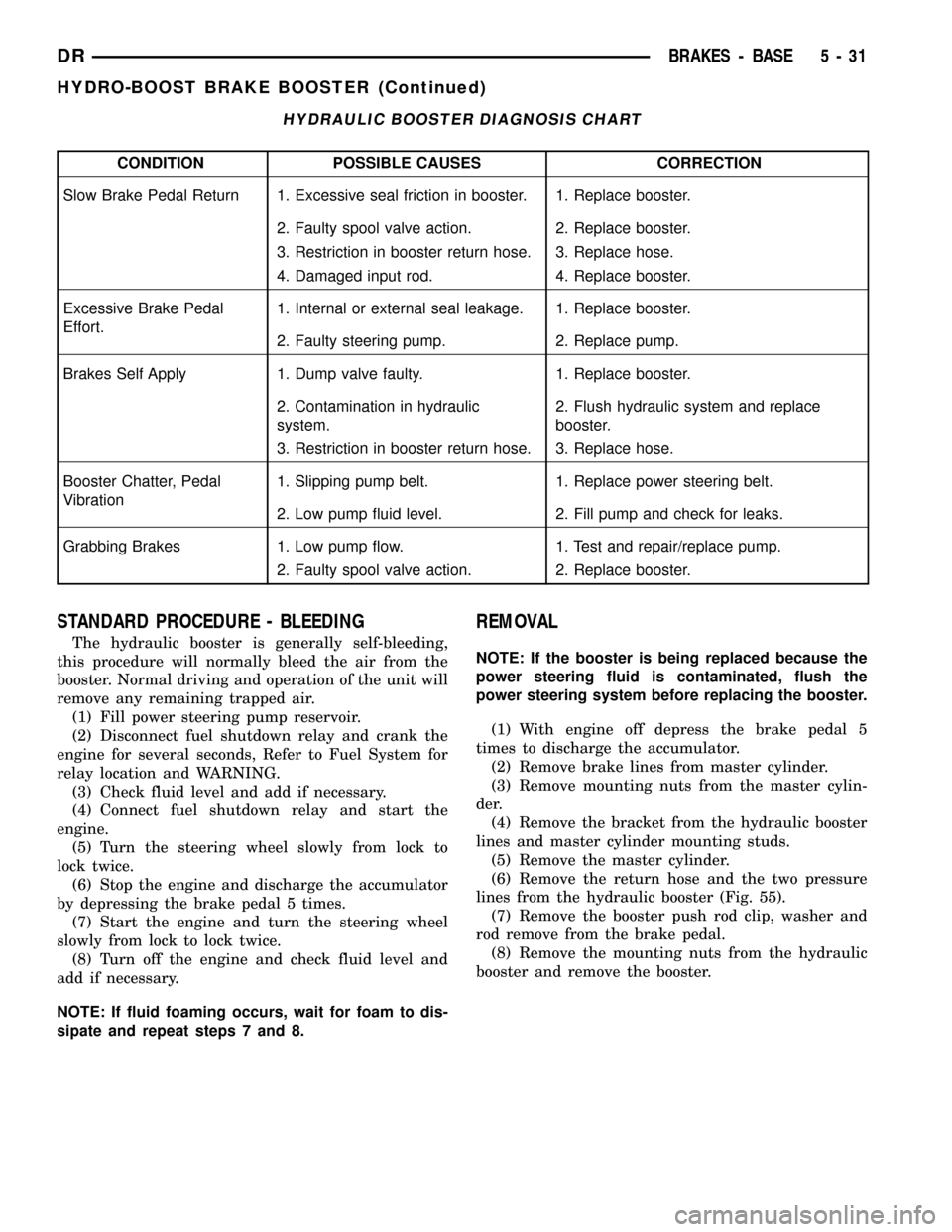
HYDRAULIC BOOSTER DIAGNOSIS CHART
CONDITION POSSIBLE CAUSES CORRECTION
Slow Brake Pedal Return 1. Excessive seal friction in booster. 1. Replace booster.
2. Faulty spool valve action. 2. Replace booster.
3. Restriction in booster return hose. 3. Replace hose.
4. Damaged input rod. 4. Replace booster.
Excessive Brake Pedal
Effort.1. Internal or external seal leakage. 1. Replace booster.
2. Faulty steering pump. 2. Replace pump.
Brakes Self Apply 1. Dump valve faulty. 1. Replace booster.
2. Contamination in hydraulic
system.2. Flush hydraulic system and replace
booster.
3. Restriction in booster return hose. 3. Replace hose.
Booster Chatter, Pedal
Vibration1. Slipping pump belt. 1. Replace power steering belt.
2. Low pump fluid level. 2. Fill pump and check for leaks.
Grabbing Brakes 1. Low pump flow. 1. Test and repair/replace pump.
2. Faulty spool valve action. 2. Replace booster.
STANDARD PROCEDURE - BLEEDING
The hydraulic booster is generally self-bleeding,
this procedure will normally bleed the air from the
booster. Normal driving and operation of the unit will
remove any remaining trapped air.
(1) Fill power steering pump reservoir.
(2) Disconnect fuel shutdown relay and crank the
engine for several seconds, Refer to Fuel System for
relay location and WARNING.
(3) Check fluid level and add if necessary.
(4) Connect fuel shutdown relay and start the
engine.
(5) Turn the steering wheel slowly from lock to
lock twice.
(6) Stop the engine and discharge the accumulator
by depressing the brake pedal 5 times.
(7) Start the engine and turn the steering wheel
slowly from lock to lock twice.
(8) Turn off the engine and check fluid level and
add if necessary.
NOTE: If fluid foaming occurs, wait for foam to dis-
sipate and repeat steps 7 and 8.
REMOVAL
NOTE: If the booster is being replaced because the
power steering fluid is contaminated, flush the
power steering system before replacing the booster.
(1) With engine off depress the brake pedal 5
times to discharge the accumulator.
(2) Remove brake lines from master cylinder.
(3) Remove mounting nuts from the master cylin-
der.
(4) Remove the bracket from the hydraulic booster
lines and master cylinder mounting studs.
(5) Remove the master cylinder.
(6) Remove the return hose and the two pressure
lines from the hydraulic booster (Fig. 55).
(7) Remove the booster push rod clip, washer and
rod remove from the brake pedal.
(8) Remove the mounting nuts from the hydraulic
booster and remove the booster.
DRBRAKES - BASE 5 - 31
HYDRO-BOOST BRAKE BOOSTER (Continued)
Page 296 of 2627

FRONT WHEEL SPEED
SENSOR
DESCRIPTION
The ABS brake system uses 3 wheel speed sensors.
A sensor is mounted to each front hub/bearings. The
third sensor is mounted on top of the rear axle dif-
ferential housing.
OPERATION
The Wheel Speed Sensor consists of a magnet sur-
rounded by windings from a single strand of wire.
The sensor sends a small AC signal to the CAB. This
signal is generated by magnetic induction. The mag-
netic induction is created when a toothed sensor ring
(exciter ring or tone wheel) passes the stationary
magnetic WSS.
When the ring gear is rotated, the exciter ring
passes the tip of the WSS. As the exciter ring tooth
approaches the tip of the WSS, the magnetic lines of
force expand, causing the magnetic field to cut across
the sensor's windings. This, in turn causes current to
flow through the WSS circuit (Fig. 1) in one direc-
tion. When the exciter ring tooth moves away from
the sensor tip, the magnetic lines of force collapse
cutting the winding in the opposite direction. This
causes the current to flow in the opposite direction.
Every time a tooth of the exciter ring passes the tip
of the WSS, an AC signal is generated. Each AC sig-
nal (positive to negative signal or sinewave) is inter-
preted by the CAB. It then compares the frequency of
the sinewave to a time value to calculate vehicle
speed. The CAB continues to monitor the frequency
to determine a deceleration rate that would indicate
a possible wheel-locking tendency.
The signal strength of any magnetic induction sen-
sor is directly affected by:
²Magnetic field strength; the stronger the mag-
netic field, the stronger the signal
²Number of windings in the sensor; more wind-
ings provide a stronger signal
²Exciter ring speed; the faster the exciter ring/
tone wheel rotates, the stronger the signal will be
²Distance between the exciter ring teeth and
WSS; the closer the WSS is to the exciter ring/tone
wheel, the stronger the signal will be
The rear WSS is not adjustable. A clearance speci-
fication has been established for manufacturing toler-
ances. If the clearance is not within these
specifications, then either the WSS or other compo-
nents may be damaged. The clearance between the
WSS and the exciter ring is 0.005 ± 0.050 in.
The assembly plant performs a ªRolls Testº on
every vehicle that leaves the assembly plant. One of
the test performed is a test of the WSS. To properlytest the sensor, the assembly plant connects test
equipment to the Data Link Connector (DLC). This
connector is located to the right of the steering col-
umn and attached to the lower portion of the instru-
ment panel (Fig. 2). The rolls test terminal is spliced
to the WSS circuit. The vehicle is then driven on a
set of rollers and the WSS output is monitored for
proper operation.
Fig. 1 Operation of the Wheel Speed Sensor
1 - MAGNETIC CORE
2 - CAB
3 - AIR GAP
4 - EXCITER RING
5 - COIL
Fig. 2 Data Link Connector - Typical
1 - 16±WAY DATA LINK CONNECTOR
DRBRAKES - ABS 5 - 47
Page 303 of 2627
Engagement problems can cause slip, chatter/shud-
der and noisy operation. The causes may be clutch
disc contamination, wear, distortion or flywheel dam-
age.
CLUTCH MISALIGNMENT
Clutch components must be in proper alignment
with the crankshaft and transmission input shaft.
Misalignment caused by excessive runout or warpage
of any clutch component will cause grab, chatter and
improper clutch release.
CLUTCH COVER AND DISC RUNOUT
Check the clutch disc before installation. Axial
(face) runout of anewdisc should not exceed 0.50
mm (0.020 in.). Measure runout about 6 mm (1/4 in.)
from the outer edge of the disc facing. Obtain
another disc if runout is excessive.
Check condition of the clutch before installation. A
warped cover or diaphragm spring will cause grab
and incomplete release or engagement. Be careful
when handling the cover and disc. Impact can distort
the cover, diaphragm spring, release fingers and the
hub of the clutch disc.
Use an alignment tool when positioning the disc on
the flywheel. The tool prevents accidental misalign-
ment which could result in cover distortion and disc
damage.
A frequent cause of clutch cover distortion (and
consequent misalignment) is improper bolt tighten-
ing.
FLYWHEEL RUNOUT
Check flywheel runout whenever misalignment is
suspected. Flywheel runout should not exceed 0.08
mm (0.003 in.). Measure runout at the outer edge of
the flywheel face with a dial indicator.
Common causes of runout are:
²heat warpage
²improper machining
²incorrect bolt tightening
²improper seating on crankshaft flange shoulder
²foreign material on crankshaft flange
Flywheel machining is not recommended. The fly-
wheel clutch surface is machined to a unique contour
and machining will negate this feature. Minor fly-
wheel scoring can be cleaned up by hand with 180
grit emery or with turning equipment. Remove only
enough material to reduce scoring (approximately
0.001 - 0.003 in.). Heavy stock removal isnot rec-
ommended.Replace the flywheel if scoring is severe
and deeper than 0.076 mm (0.003 in.). Excessive
stock removal can result in flywheel cracking or
warpage after installation; it can also weaken the fly-
wheel and interfere with proper clutch release.
Clean the crankshaft flange before mounting the
flywheel. Dirt and grease on the flange surface may
cock the flywheel causing excessive runout. Use new
bolts when remounting a flywheel and secure the
bolts with Mopar Lock And Seal or equivalent.
Tighten flywheel bolts to specified torque only. Over-
tightening can distort the flywheel hub causing
runout.
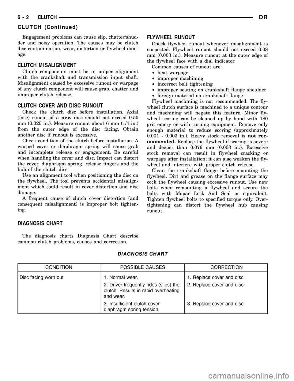
DIAGNOSIS CHART
The diagnosis charts Diagnosis Chart describe
common clutch problems, causes and correction.
DIAGNOSIS CHART
CONDITION POSSIBLE CAUSES CORRECTION
Disc facing worn out 1. Normal wear. 1. Replace cover and disc.
2. Driver frequently rides (slips) the
clutch. Results in rapid overheating
and wear.2. Replace cover and disc.
3. Insufficient clutch cover
diaphragm spring tension.3. Replace cover and disc.
6 - 2 CLUTCHDR
CLUTCH (Continued)
Page 304 of 2627
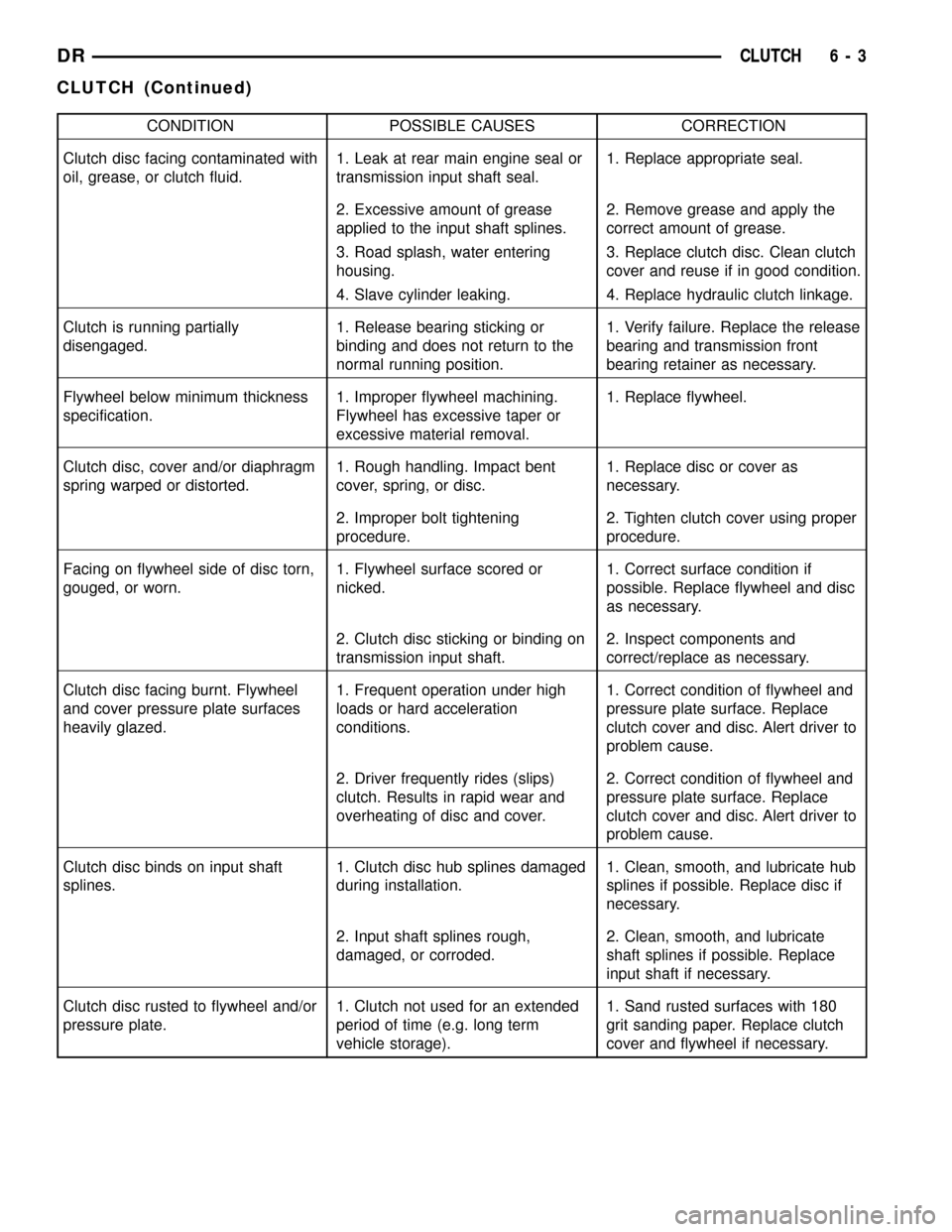
CONDITION POSSIBLE CAUSES CORRECTION
Clutch disc facing contaminated with
oil, grease, or clutch fluid.1. Leak at rear main engine seal or
transmission input shaft seal.1. Replace appropriate seal.
2. Excessive amount of grease
applied to the input shaft splines.2. Remove grease and apply the
correct amount of grease.
3. Road splash, water entering
housing.3. Replace clutch disc. Clean clutch
cover and reuse if in good condition.
4. Slave cylinder leaking. 4. Replace hydraulic clutch linkage.
Clutch is running partially
disengaged.1. Release bearing sticking or
binding and does not return to the
normal running position.1. Verify failure. Replace the release
bearing and transmission front
bearing retainer as necessary.
Flywheel below minimum thickness
specification.1. Improper flywheel machining.
Flywheel has excessive taper or
excessive material removal.1. Replace flywheel.
Clutch disc, cover and/or diaphragm
spring warped or distorted.1. Rough handling. Impact bent
cover, spring, or disc.1. Replace disc or cover as
necessary.
2. Improper bolt tightening
procedure.2. Tighten clutch cover using proper
procedure.
Facing on flywheel side of disc torn,
gouged, or worn.1. Flywheel surface scored or
nicked.1. Correct surface condition if
possible. Replace flywheel and disc
as necessary.
2. Clutch disc sticking or binding on
transmission input shaft.2. Inspect components and
correct/replace as necessary.
Clutch disc facing burnt. Flywheel
and cover pressure plate surfaces
heavily glazed.1. Frequent operation under high
loads or hard acceleration
conditions.1. Correct condition of flywheel and
pressure plate surface. Replace
clutch cover and disc. Alert driver to
problem cause.
2. Driver frequently rides (slips)
clutch. Results in rapid wear and
overheating of disc and cover.2. Correct condition of flywheel and
pressure plate surface. Replace
clutch cover and disc. Alert driver to
problem cause.
Clutch disc binds on input shaft
splines.1. Clutch disc hub splines damaged
during installation.1. Clean, smooth, and lubricate hub
splines if possible. Replace disc if
necessary.
2. Input shaft splines rough,
damaged, or corroded.2. Clean, smooth, and lubricate
shaft splines if possible. Replace
input shaft if necessary.
Clutch disc rusted to flywheel and/or
pressure plate.1. Clutch not used for an extended
period of time (e.g. long term
vehicle storage).1. Sand rusted surfaces with 180
grit sanding paper. Replace clutch
cover and flywheel if necessary.
DRCLUTCH 6 - 3
CLUTCH (Continued)
Page 305 of 2627
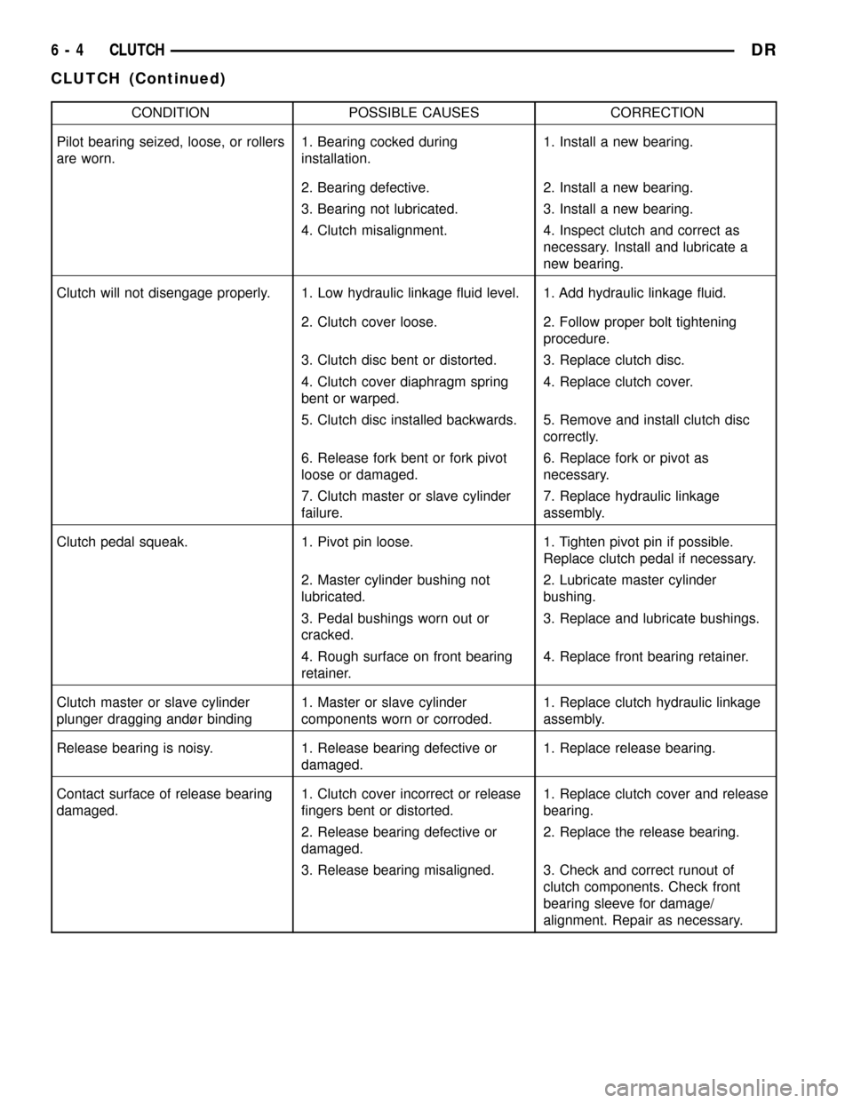
CONDITION POSSIBLE CAUSES CORRECTION
Pilot bearing seized, loose, or rollers
are worn.1. Bearing cocked during
installation.1. Install a new bearing.
2. Bearing defective. 2. Install a new bearing.
3. Bearing not lubricated. 3. Install a new bearing.
4. Clutch misalignment. 4. Inspect clutch and correct as
necessary. Install and lubricate a
new bearing.
Clutch will not disengage properly. 1. Low hydraulic linkage fluid level. 1. Add hydraulic linkage fluid.
2. Clutch cover loose. 2. Follow proper bolt tightening
procedure.
3. Clutch disc bent or distorted. 3. Replace clutch disc.
4. Clutch cover diaphragm spring
bent or warped.4. Replace clutch cover.
5. Clutch disc installed backwards. 5. Remove and install clutch disc
correctly.
6. Release fork bent or fork pivot
loose or damaged.6. Replace fork or pivot as
necessary.
7. Clutch master or slave cylinder
failure.7. Replace hydraulic linkage
assembly.
Clutch pedal squeak. 1. Pivot pin loose. 1. Tighten pivot pin if possible.
Replace clutch pedal if necessary.
2. Master cylinder bushing not
lubricated.2. Lubricate master cylinder
bushing.
3. Pedal bushings worn out or
cracked.3. Replace and lubricate bushings.
4. Rough surface on front bearing
retainer.4. Replace front bearing retainer.
Clutch master or slave cylinder
plunger dragging andùr binding1. Master or slave cylinder
components worn or corroded.1. Replace clutch hydraulic linkage
assembly.
Release bearing is noisy. 1. Release bearing defective or
damaged.1. Replace release bearing.
Contact surface of release bearing
damaged.1. Clutch cover incorrect or release
fingers bent or distorted.1. Replace clutch cover and release
bearing.
2. Release bearing defective or
damaged.2. Replace the release bearing.
3. Release bearing misaligned. 3. Check and correct runout of
clutch components. Check front
bearing sleeve for damage/
alignment. Repair as necessary.
6 - 4 CLUTCHDR
CLUTCH (Continued)
Page 306 of 2627
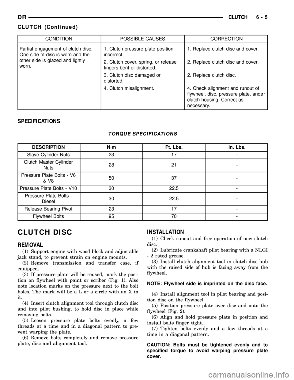
CONDITION POSSIBLE CAUSES CORRECTION
Partial engagement of clutch disc.
One side of disc is worn and the
other side is glazed and lightly
worn.1. Clutch pressure plate position
incorrect.1. Replace clutch disc and cover.
2. Clutch cover, spring, or release
fingers bent or distorted.2. Replace clutch disc and cover.
3. Clutch disc damaged or
distorted.2. Replace clutch disc.
4. Clutch misalignment. 4. Check alignment and runout of
flywheel, disc, pressure plate, andùr
clutch housing. Correct as
necessary.
SPECIFICATIONS
TORQUE SPECIFICATIONS
DESCRIPTION N´m Ft. Lbs. In. Lbs.
Slave Cylinder Nuts 23 17 -
Clutch Master Cylinder
Nuts28 21 -
Pressure Plate Bolts - V6
&V850 37 -
Pressure Plate Bolts - V10 30 22.5 -
Pressure Plate Bolts -
Diesel30 22.5 -
Release Bearing Pivot 23 17 -
Flywheel Bolts 95 70 -
CLUTCH DISC
REMOVAL
(1) Support engine with wood block and adjustable
jack stand, to prevent strain on engine mounts.
(2) Remove transmission and transfer case, if
equipped.
(3) If pressure plate will be reused, mark the posi-
tion on flywheel with paint or scriber (Fig. 1). Also
note location marks on the pressure next to the bolt
holes. The mark will be a L or a circle with an X in
it.
(4) Insert clutch alignment tool through clutch disc
and into pilot bushing, to hold disc in place while
removing bolts.
(5) Loosen pressure plate bolts evenly, a few
threads at a time and in a diagonal pattern to pre-
vent warping the plate.
(6) Remove bolts completely and remove pressure
plate, disc and alignment tool.
INSTALLATION
(1) Check runout and free operation of new clutch
disc.
(2) Lubricate crankshaft pilot bearing with a NLGI
- 2 rated grease.
(3) Install clutch alignment tool in clutch disc hub
with the raised side of hub is facing away from the
flywheel.
NOTE: Flywheel side is imprinted on the disc face.
(4) Install alignment tool in pilot bearing and posi-
tion disc on the flywheel.
(5) Position pressure plate over disc and onto the
flywheel (Fig. 2).
(6) Align and hold pressure plate in position and
install bolts finger tight.
(7) Tighten bolts evenly and a few threads at a
time in a diagonal pattern.
CAUTION: Bolts must be tightened evenly and to
specified torque to avoid warping pressure plate
cover.
DRCLUTCH 6 - 5
CLUTCH (Continued)
Page 312 of 2627

Common causes of runout are:
²heat warpage
²improper machining
²incorrect bolt tightening
²improper seating on crankshaft flange shoulder
²foreign material on crankshaft flange
Flywheel machining is not recommended. The fly-
wheel clutch surface is machined to a unique contour
and machining will negate this feature. Minor fly-
wheel scoring can be cleaned up by hand with 180
grit emery or with surface grinding equipment.
Remove only enough material to reduce scoring
(approximately 0.001 - 0.003 in.). Heavy stock
removal isnot recommended.Replace the flywheel
if scoring is severe and deeper than 0.076 mm (0.003
in.). Excessive stock removal can result in flywheel
cracking or warpage after installation; it can also
weaken the flywheel and interfere with proper clutch
release.
Clean the crankshaft flange before mounting the
flywheel. Dirt and grease on the flange surface may
cock the flywheel causing excessive runout. Use new
bolts when remounting a flywheel and secure the
bolts with Mopar Lock And Seal or equivalent.
Tighten flywheel bolts to specified torque only. Over-
tightening can distort the flywheel hub causing
runout.
REMOVAL
(1) Remove transmission.
(2) Remove pressure plate and clutch.
(3) Remove flywheel bolts and remove flywheel.
DISASSEMBLY
NOTE: If the teeth are worn or damaged, the fly-
wheel should be replaced as an assembly. This is
the recommended repair. In cases where a new fly-
wheel is not readily available, (V10/Diesel Engine
only) a replacement ring gear can be installed. The
following procedure must be observed to avoid
damaging the flywheel and replacement gear.
WARNING: WEAR PROTECTIVE GOGGLES OR
SAFETY GLASSES WHILE CUTTING RING GEAR.
(1) Mark position of the old gear for alignment ref-
erence on the flywheel. Use a scriber for this pur-
pose.
(2) Remove the old gear by cutting most of the way
through it (at one point) with an abrasive cut-off
wheel. Then complete removal with a cold chisel or
punch.
ASSEMBLY
NOTE: The ring gear is a shrink fit on the flywheel.
This means the gear must be expanded by heating
in order to install it. The method of heating and
expanding the gear is extremely important. Every
surface of the gear must be heated at the same
time to produce uniform expansion. An oven or
similar enclosed heating device must be used. Tem-
perature required for uniform expansion is approxi-
mately 375É F.
CAUTION: Do not use an oxy/acetylene torch to
remove the old gear, or to heat and expand a new
gear. The high temperature of the torch flame can
cause localized heating that will damage the fly-
wheel. In addition, using the torch to heat a replace-
ment gear will cause uneven heating and
expansion. The torch flame can also anneal the
gear teeth resulting in rapid wear and damage after
installation.
WARNING: WEAR PROTECTIVE GOGGLES OR
SAFETY GLASSES AND HEAT RESISTENT GLOVES
WHEN HANDLING A HEATED RING GEAR.
(1) The heated gear must be installed evenly to
avoid misalignment or distortion.
(2)
Position and install the heated ring gear on the
flywheel with a shop press and a suitable press plates.
(3) Place flywheel on work bench and let it cool in
normal shop air. Allow the ring gear to cool down
completely before installation it on the engine.
CAUTION: Do not use water or compressed air to
cool the flywheel. The rapid cooling produced by
water or compressed air will distort or crack the
new gear.
INSTALLATION
(1) Install flywheel on the crank shaft.
(2) Install flywheel bolts and tighten to 95 N´m
(70 ft. lbs.).
(3) Install clutch.
(4) Install transmission.
PILOT BEARING
REMOVAL
(1) Remove transmission.
(2) Remove clutch disc.
(3) Use a suitable blind hole puller to remove pilot
bearing.
DRCLUTCH 6 - 11
FLYWHEEL (Continued)
Page 322 of 2627
exhaust pipe may indicate a faulty cylinder head gas-
ket, cracked engine cylinder block or cylinder head.
A convenient check for exhaust gas leakage into
cooling system is provided by a commercially avail-
able Block Leak Check tool. Follow manufacturers
instructions when using this product.
COMBUSTION LEAKAGE TEST - WITHOUT
PRESSURE TESTER
DO NOT WASTE reusable coolant. If the solution
is clean, drain the coolant into a clean container for
reuse.
WARNING: DO NOT REMOVE CYLINDER BLOCK
DRAIN PLUGS OR LOOSEN RADIATOR DRAIN-
COCK WITH SYSTEM HOT AND UNDER PRESSURE.
SERIOUS BURNS FROM COOLANT CAN OCCUR.
Drain sufficient coolant to allow thermostat
removal. (Refer to 7 - COOLING/ENGINE/ENGINECOOLANT THERMOSTAT - REMOVAL). Remove
accessory drive belt (Refer to 7 - COOLING/ACCES-
SORY DRIVE/DRIVE BELTS - REMOVAL).
Add coolant to radiator to bring level to within 6.3
mm (1/4 in) of the top of the thermostat housing.
CAUTION: Avoid overheating. Do not operate
engine for an excessive period of time. Open drain-
cock immediately after test to eliminate boil over.
Start engine and accelerate rapidly three times, to
approximately 3000 rpm while observing coolant. If
internal engine combustion gases are leaking into
cooling system, bubbles will appear in coolant. If bub-
bles do not appear, internal combustion gas leakage
is not present.
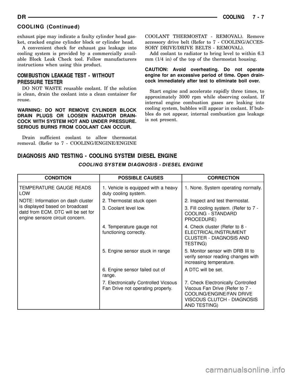
DIAGNOSIS AND TESTING - COOLING SYSTEM DIESEL ENGINE
COOLING SYSTEM DIAGNOSIS - DIESEL ENGINE
CONDITION POSSIBLE CAUSES CORRECTION
TEMPERATURE GAUGE READS
LOW1. Vehicle is equipped with a heavy
duty cooling system.1. None. System operating normally.
NOTE: Information on dash cluster
is displayed based on broadcast
datd from ECM. DTC will be set for
engine sensore circuit concern.2. Thermostat stuck open 2. Inspect and test thermostat.
3. Coolant level low. 3. Fill cooling system. (Refer to 7 -
COOLING - STANDARD
PROCEDURE)
4. Temperature gauge not
functioning correctly.4. Check cluster (Refer to 8 -
ELECTRICAL/INSTRUMENT
CLUSTER - DIAGNOSIS AND
TESTING)
5. Engine sensor stuck in range 5. Monitor sensor with DRB III to
verify sensor reading changes with
increasing temperature.
6. Engine sensor failed out of
range.A DTC will be set.
7. Electronically Controlled Vicsous
Fan Drive not operating properly.7. Check Electronically Controlled
Viscous Fan Drive (Refer to 7 -
COOLING/ENGINE/FAN DRIVE
VISCOUS CLUTCH - DIAGNOSIS
AND TESTING)
DRCOOLING 7 - 7
COOLING (Continued)
Page 323 of 2627
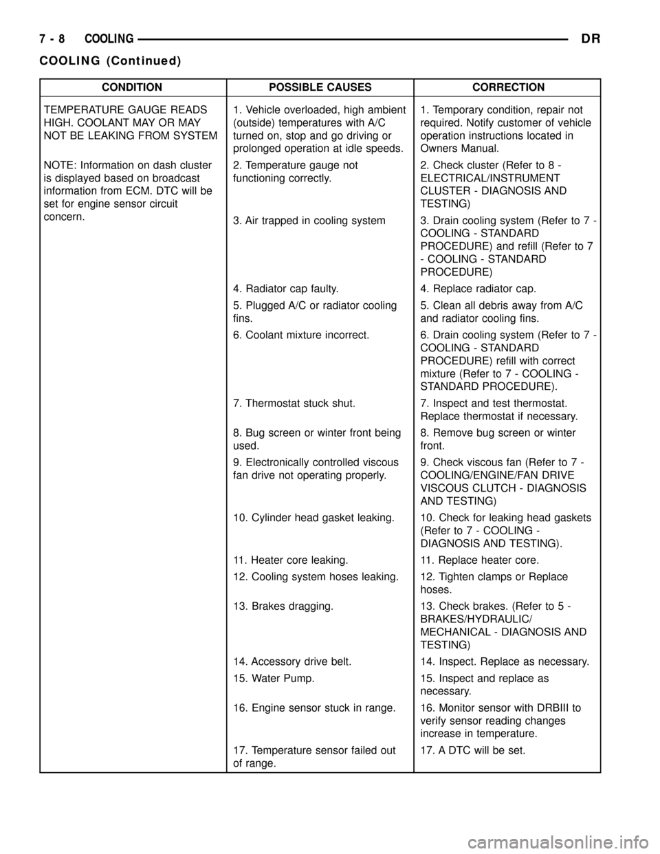
CONDITION POSSIBLE CAUSES CORRECTION
TEMPERATURE GAUGE READS
HIGH. COOLANT MAY OR MAY
NOT BE LEAKING FROM SYSTEM1. Vehicle overloaded, high ambient
(outside) temperatures with A/C
turned on, stop and go driving or
prolonged operation at idle speeds.1. Temporary condition, repair not
required. Notify customer of vehicle
operation instructions located in
Owners Manual.
NOTE: Information on dash cluster
is displayed based on broadcast
information from ECM. DTC will be
set for engine sensor circuit
concern.2. Temperature gauge not
functioning correctly.2. Check cluster (Refer to 8 -
ELECTRICAL/INSTRUMENT
CLUSTER - DIAGNOSIS AND
TESTING)
3. Air trapped in cooling system 3. Drain cooling system (Refer to 7 -
COOLING - STANDARD
PROCEDURE) and refill (Refer to 7
- COOLING - STANDARD
PROCEDURE)
4. Radiator cap faulty. 4. Replace radiator cap.
5. Plugged A/C or radiator cooling
fins.5. Clean all debris away from A/C
and radiator cooling fins.
6. Coolant mixture incorrect. 6. Drain cooling system (Refer to 7 -
COOLING - STANDARD
PROCEDURE) refill with correct
mixture (Refer to 7 - COOLING -
STANDARD PROCEDURE).
7. Thermostat stuck shut. 7. Inspect and test thermostat.
Replace thermostat if necessary.
8. Bug screen or winter front being
used.8. Remove bug screen or winter
front.
9. Electronically controlled viscous
fan drive not operating properly.9. Check viscous fan (Refer to 7 -
COOLING/ENGINE/FAN DRIVE
VISCOUS CLUTCH - DIAGNOSIS
AND TESTING)
10. Cylinder head gasket leaking. 10. Check for leaking head gaskets
(Refer to 7 - COOLING -
DIAGNOSIS AND TESTING).
11. Heater core leaking. 11. Replace heater core.
12. Cooling system hoses leaking. 12. Tighten clamps or Replace
hoses.
13. Brakes dragging. 13. Check brakes. (Refer to 5 -
BRAKES/HYDRAULIC/
MECHANICAL - DIAGNOSIS AND
TESTING)
14. Accessory drive belt. 14. Inspect. Replace as necessary.
15. Water Pump. 15. Inspect and replace as
necessary.
16. Engine sensor stuck in range. 16. Monitor sensor with DRBIII to
verify sensor reading changes
increase in temperature.
17. Temperature sensor failed out
of range.17. A DTC will be set.
7 - 8 COOLINGDR
COOLING (Continued)