spark DODGE RAM 1500 1998 2.G Workshop Manual
[x] Cancel search | Manufacturer: DODGE, Model Year: 1998, Model line: RAM 1500, Model: DODGE RAM 1500 1998 2.GPages: 2627
Page 3 of 2627
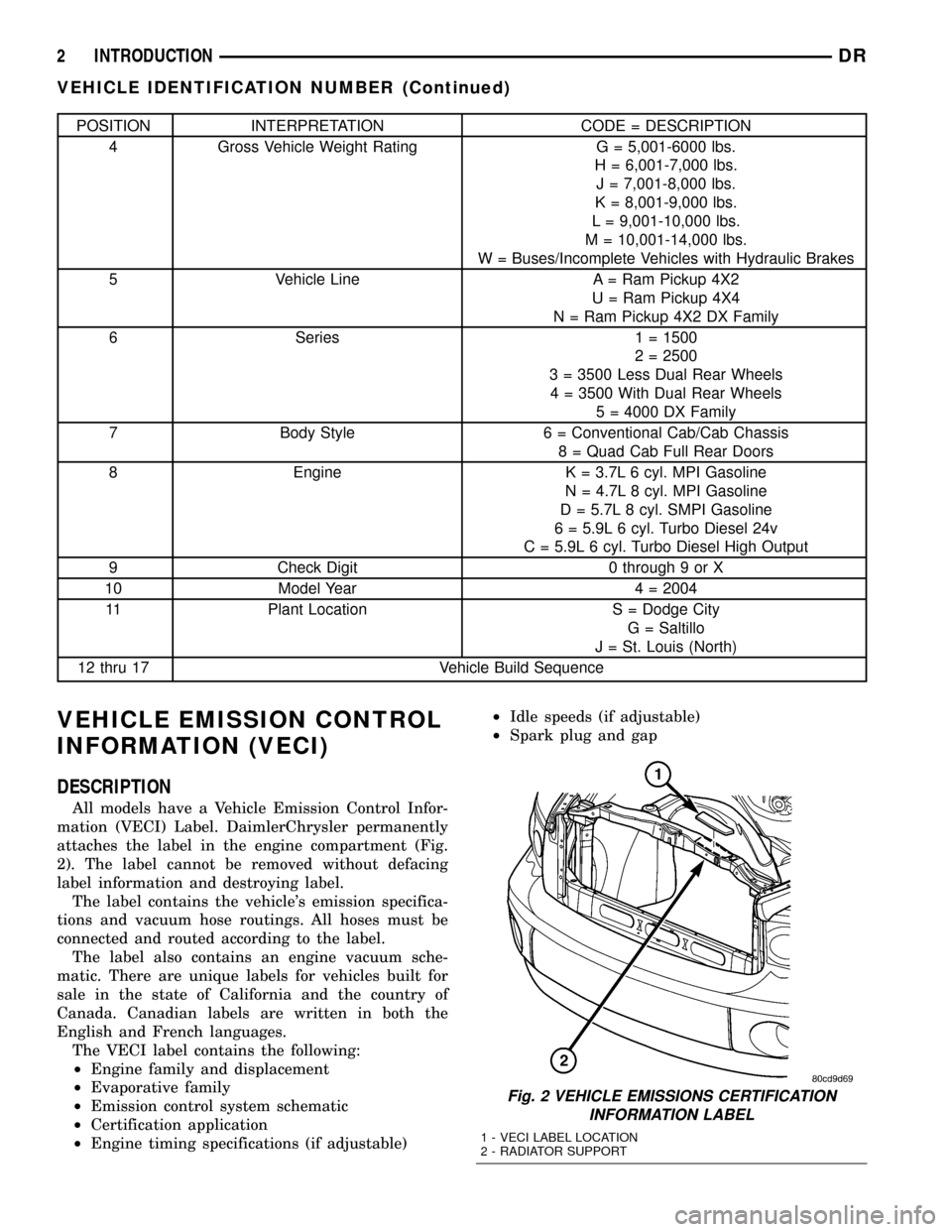
POSITION INTERPRETATION CODE = DESCRIPTION
4 Gross Vehicle Weight Rating G = 5,001-6000 lbs.
H = 6,001-7,000 lbs.
J = 7,001-8,000 lbs.
K = 8,001-9,000 lbs.
L = 9,001-10,000 lbs.
M = 10,001-14,000 lbs.
W = Buses/Incomplete Vehicles with Hydraulic Brakes
5 Vehicle Line A = Ram Pickup 4X2
U = Ram Pickup 4X4
N = Ram Pickup 4X2 DX Family
6 Series 1 = 1500
2 = 2500
3 = 3500 Less Dual Rear Wheels
4 = 3500 With Dual Rear Wheels
5 = 4000 DX Family
7 Body Style 6 = Conventional Cab/Cab Chassis
8 = Quad Cab Full Rear Doors
8 Engine K = 3.7L 6 cyl. MPI Gasoline
N = 4.7L 8 cyl. MPI Gasoline
D = 5.7L 8 cyl. SMPI Gasoline
6 = 5.9L 6 cyl. Turbo Diesel 24v
C = 5.9L 6 cyl. Turbo Diesel High Output
9 Check Digit 0 through 9 or X
10 Model Year 4 = 2004
11 Plant Location S = Dodge City
G = Saltillo
J = St. Louis (North)
12 thru 17 Vehicle Build Sequence
VEHICLE EMISSION CONTROL
INFORMATION (VECI)
DESCRIPTION
All models have a Vehicle Emission Control Infor-
mation (VECI) Label. DaimlerChrysler permanently
attaches the label in the engine compartment (Fig.
2). The label cannot be removed without defacing
label information and destroying label.
The label contains the vehicle's emission specifica-
tions and vacuum hose routings. All hoses must be
connected and routed according to the label.
The label also contains an engine vacuum sche-
matic. There are unique labels for vehicles built for
sale in the state of California and the country of
Canada. Canadian labels are written in both the
English and French languages.
The VECI label contains the following:
²Engine family and displacement
²Evaporative family
²Emission control system schematic
²Certification application
²Engine timing specifications (if adjustable)²Idle speeds (if adjustable)
²Spark plug and gap
Fig. 2 VEHICLE EMISSIONS CERTIFICATION
INFORMATION LABEL
1 - VECI LABEL LOCATION
2 - RADIATOR SUPPORT
2 INTRODUCTIONDR
VEHICLE IDENTIFICATION NUMBER (Continued)
Page 20 of 2627
²Trailer towing.
²Snowplowing.
²Heavy Loading.
²Taxi, police, or delivery service (commercial ser-
vice).
²Off-road or desert operation.
²If equipped for and operating with E-85
(ethanol) fuel.NOTE: If ANY of these apply to the vehicle then
change the engine oil every 3,000 miles (5 000 km)
or 3 months, whichever comes first and follow
schedule ªBº of the(Maintenance Schedules(sec-
tion of this manual.
If none of these apply to the vehicle, then change
the engine oil at every interval shown on schedule
(A(of the(Maintenance Schedules(section of this
manual.
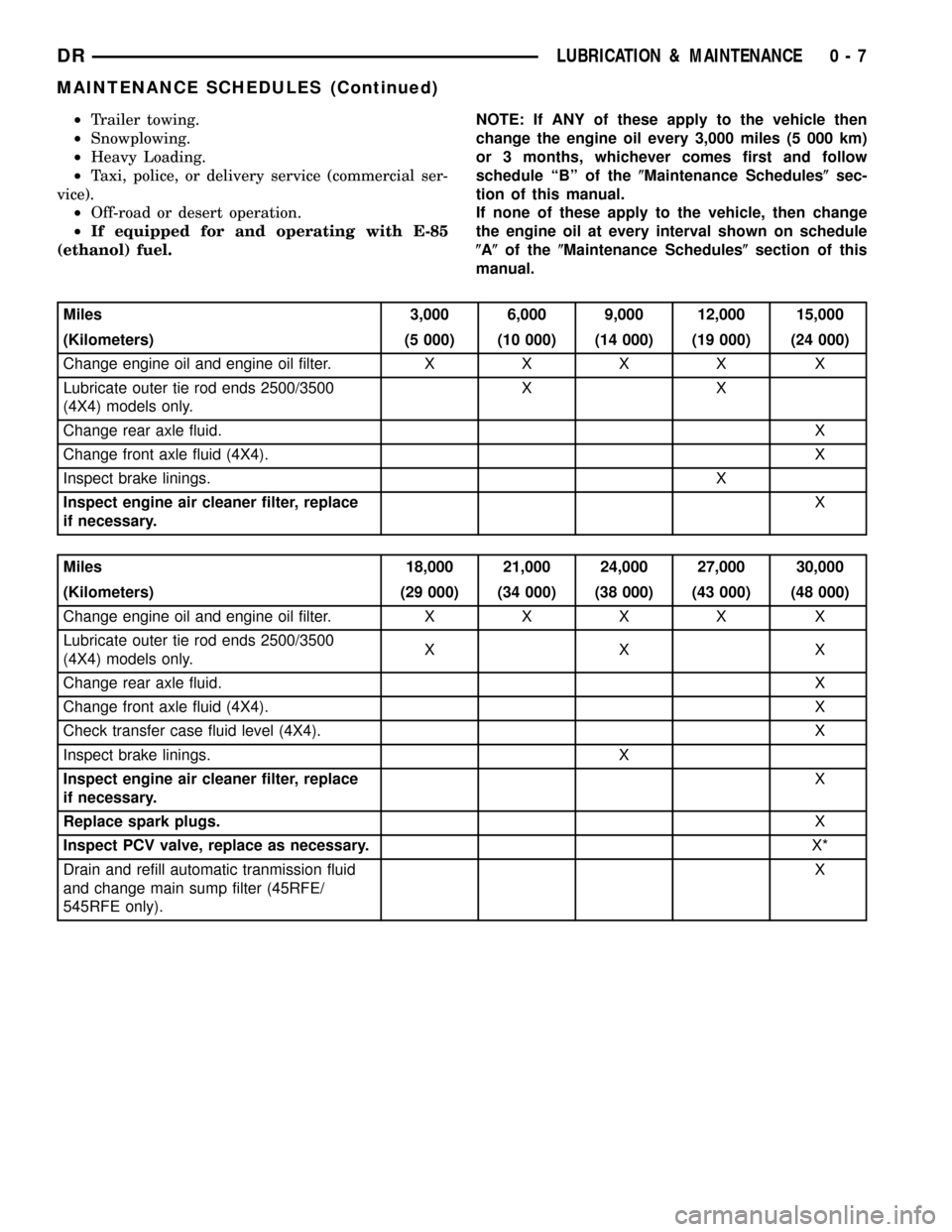
Miles 3,000 6,000 9,000 12,000 15,000
(Kilometers) (5 000) (10 000) (14 000) (19 000) (24 000)
Change engine oil and engine oil filter.XXXX X
Lubricate outer tie rod ends 2500/3500
(4X4) models only.XX
Change rear axle fluid.X
Change front axle fluid (4X4).X
Inspect brake linings.X
Inspect engine air cleaner filter, replace
if necessary.X
Miles 18,000 21,000 24,000 27,000 30,000
(Kilometers) (29 000) (34 000) (38 000) (43 000) (48 000)
Change engine oil and engine oil filter.XXXX X
Lubricate outer tie rod ends 2500/3500
(4X4) models only.XX X
Change rear axle fluid.X
Change front axle fluid (4X4).X
Check transfer case fluid level (4X4). X
Inspect brake linings. X
Inspect engine air cleaner filter, replace
if necessary.X
Replace spark plugs.X
Inspect PCV valve, replace as necessary.X*
Drain and refill automatic tranmission fluid
and change main sump filter (45RFE/
545RFE only).X
DRLUBRICATION & MAINTENANCE 0 - 7
MAINTENANCE SCHEDULES (Continued)
Page 21 of 2627
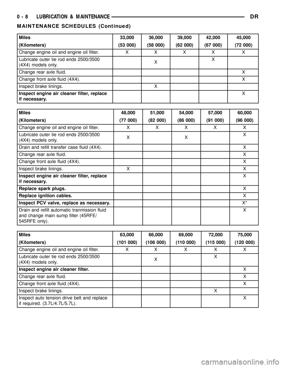
Miles 33,000 36,000 39,000 42,000 45,000
(Kilometers) (53 000) (58 000) (62 000) (67 000) (72 000)
Change engine oil and engine oil filter.XXXX X
Lubricate outer tie rod ends 2500/3500
(4X4) models only.XX
Change rear axle fluid.X
Change front axle fluid (4X4).X
Inspect brake linings. X
Inspect engine air cleaner filter, replace
if necessary.X
Miles 48,000 51,000 54,000 57,000 60,000
(Kilometers) (77 000) (82 000) (86 000) (91 000) (96 000)
Change engine oil and engine oil filter.XXXX X
Lubricate outer tie rod ends 2500/3500
(4X4) models only.XXX
Drain and refill transfer case fluid (4X4). X
Change rear axle fluid.X
Change front axle fluid (4X4).X
Inspect brake linings. X X
Inspect engine air cleaner filter, replace
if necessary.X
Replace spark plugs.X
Replace ignition cables.X
Inspect PCV valve, replace as necessary.X*
Drain and refill automatic tranmission fluid
and change main sump filter (45RFE/
545RFE only).X
Miles 63,000 66,000 69,000 72,000 75,000
(Kilometers) (101 000) (106 000) (110 000) (115 000) (120 000)
Change engine oil and engine oil filter. X X X X X
Lubricate outer tie rod ends 2500/3500
(4X4) models only.XX
Inspect engine air cleaner filter.X
Change rear axle fluid.X
Change front axle fluid (4X4).X
Inspect brake linings.X
Inspect auto tension drive belt and replace
if required. (3.7L/4.7L/5.7L).X
0 - 8 LUBRICATION & MAINTENANCEDR
MAINTENANCE SCHEDULES (Continued)
Page 22 of 2627
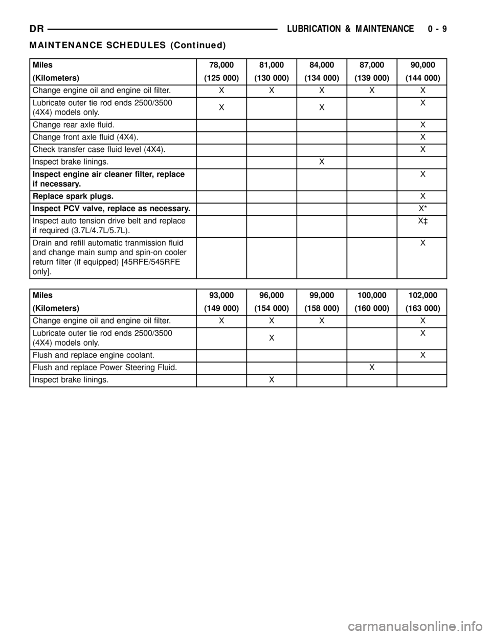
Miles 78,000 81,000 84,000 87,000 90,000
(Kilometers) (125 000) (130 000) (134 000) (139 000) (144 000)
Change engine oil and engine oil filter.XXXX X
Lubricate outer tie rod ends 2500/3500
(4X4) models only.XXX
Change rear axle fluid.X
Change front axle fluid (4X4).X
Check transfer case fluid level (4X4). X
Inspect brake linings. X
Inspect engine air cleaner filter, replace
if necessary.X
Replace spark plugs.X
Inspect PCV valve, replace as necessary.X*
Inspect auto tension drive belt and replace
if required (3.7L/4.7L/5.7L).X³
Drain and refill automatic tranmission fluid
and change main sump and spin-on cooler
return filter (if equipped) [45RFE/545RFE
only].X
Miles 93,000 96,000 99,000 100,000 102,000
(Kilometers) (149 000) (154 000) (158 000) (160 000) (163 000)
Change engine oil and engine oil filter. X X X X
Lubricate outer tie rod ends 2500/3500
(4X4) models only.XX
Flush and replace engine coolant.X
Flush and replace Power Steering Fluid. X
Inspect brake linings. X
DRLUBRICATION & MAINTENANCE 0 - 9
MAINTENANCE SCHEDULES (Continued)
Page 23 of 2627
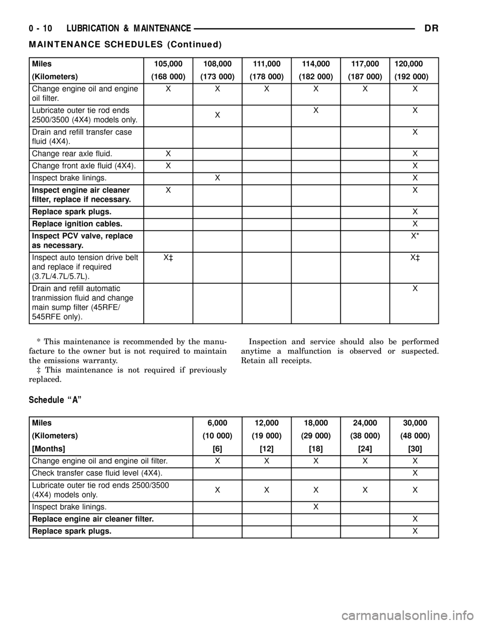
Miles 105,000 108,000 111,000 114,000 117,000 120,000
(Kilometers) (168 000) (173 000) (178 000) (182 000) (187 000) (192 000)
Change engine oil and engine
oil filter.XXXXX X
Lubricate outer tie rod ends
2500/3500 (4X4) models only.XXX
Drain and refill transfer case
fluid (4X4).X
Change rear axle fluid. X X
Change front axle fluid (4X4). X X
Inspect brake linings. X X
Inspect engine air cleaner
filter, replace if necessary.XX
Replace spark plugs.X
Replace ignition cables.X
Inspect PCV valve, replace
as necessary.X*
Inspect auto tension drive belt
and replace if required
(3.7L/4.7L/5.7L).X³ X³
Drain and refill automatic
tranmission fluid and change
main sump filter (45RFE/
545RFE only).X
* This maintenance is recommended by the manu-
facture to the owner but is not required to maintain
the emissions warranty.
³ This maintenance is not required if previously
replaced.Inspection and service should also be performed
anytime a malfunction is observed or suspected.
Retain all receipts.
Schedule ªAº
Miles 6,000 12,000 18,000 24,000 30,000
(Kilometers) (10 000) (19 000) (29 000) (38 000) (48 000)
[Months] [6] [12] [18] [24] [30]
Change engine oil and engine oil filter.XXXX X
Check transfer case fluid level (4X4). X
Lubricate outer tie rod ends 2500/3500
(4X4) models only.XXXX X
Inspect brake linings. X
Replace engine air cleaner filter.X
Replace spark plugs.X
0 - 10 LUBRICATION & MAINTENANCEDR
MAINTENANCE SCHEDULES (Continued)
Page 24 of 2627
![DODGE RAM 1500 1998 2.G Workshop Manual Miles 36,000 42,000 48,000 54,000 60,000 66,000
(Kilometers) (58 000) (67 000) (77 000) (84 000) (96 000) (106 000)
[Months] [36] [42] [48] [54] [60] [66]
Change engine oil and engine
oil filter.XXXXX DODGE RAM 1500 1998 2.G Workshop Manual Miles 36,000 42,000 48,000 54,000 60,000 66,000
(Kilometers) (58 000) (67 000) (77 000) (84 000) (96 000) (106 000)
[Months] [36] [42] [48] [54] [60] [66]
Change engine oil and engine
oil filter.XXXXX](/img/12/5702/w960_5702-23.png)
Miles 36,000 42,000 48,000 54,000 60,000 66,000
(Kilometers) (58 000) (67 000) (77 000) (84 000) (96 000) (106 000)
[Months] [36] [42] [48] [54] [60] [66]
Change engine oil and engine
oil filter.XXXXX
X
Check transfer case fluid level
(4X4).X
Lubricate outer tie rod ends
2500/3500 (4X4) models only.XXXXX X
Flush and replace engine
coolant at 60 months,
regardless of mileage.X
Inspect brake linings. X X
Replace engine air cleaner
filter.X
Replace spark plugs.X
Inspect PCV valve, replace
as necessary.X*
Replace ignition cables.X
Miles 72,000 78,000 84,000 90,000 96,000 100,000
(Kilometers) (115000) (125 000) (134 000) (144 000) (154 000) 160 000
[Months] [72] [78] [84] [90] [96]
Change engine oil and engine
oil filter.XXXXX
Lubricate outer tie rod ends
2500/3500 (4X4) models only.XXXXX
Check transfer case fluid level
(4X4).X
Flush and replace Power
Steering Fluid.X
Inspect brake linings. X X
Replace engine air cleaner
filter.X
Replace spark plugs.X
Inspect PCV valve, replace
as necessary.X*
Inspect auto tension drive belt
and replace if required
(3.7L/4.7L/5.7L).X
Drain and refill automatic
tranmission fluid and change
main sump filter and spin-on
cooler return filter (if
equipped) [45RFE/545RFE
only].X
DRLUBRICATION & MAINTENANCE 0 - 11
MAINTENANCE SCHEDULES (Continued)
Page 25 of 2627
![DODGE RAM 1500 1998 2.G Workshop Manual Miles 102,000 108,000 114,000 120,000
(Kilometers) (163 000) (173 000) (182 000) (192 000)
[Months] [102] [108] [114] [120]
Change engine oil and engine oil filter. X X X X
Drain and refill transfer c DODGE RAM 1500 1998 2.G Workshop Manual Miles 102,000 108,000 114,000 120,000
(Kilometers) (163 000) (173 000) (182 000) (192 000)
[Months] [102] [108] [114] [120]
Change engine oil and engine oil filter. X X X X
Drain and refill transfer c](/img/12/5702/w960_5702-24.png)
Miles 102,000 108,000 114,000 120,000
(Kilometers) (163 000) (173 000) (182 000) (192 000)
[Months] [102] [108] [114] [120]
Change engine oil and engine oil filter. X X X X
Drain and refill transfer case fluid (4X4). X
Flush and replace engine coolant, if not done at 60 mos. X
Lubricate outer tie rod ends 2500/3500 (4X4) models
only.XXX X
Inspect brake linings. X
Inspect auto tension drive belt and replace if required
(3.7L/4.7L/5.7L).X³X³
Replace ignition cables.X
Replace engine air cleaner filter.X
Replace spark plugs.X
Inspect PCV Valve, replace as necessary X*
* This maintenance is recommended by the manu-
facture to the owner but is not required to maintain
the emissions warranty.
³ This maintenance is not required if previously
replaced.
Inspection and service should also be performed
anytime a malfunction is observed or suspected.
WARNING: You can be badly injured working on or
around a motor vehicle. Do only that service work
for which you have the knowledge and the right
equipment. If you have any doubt about your ability
to perform a service job, take your vehicle to a
competent mechanic.
MAINTENANCE SCHEDULES Ð 24±VALVE
CUMMINS TURBO DIESEL
There are two maintenance schedules that show
therequiredservice for your vehicle.
First is ScheduleªBº. It is for vehicles that are
operated under the conditions that are listed below
and at the beginning of the schedule.
²Day or night temperatures are below 0É C (32É
F).
²Stop and go driving.
²Extensive engine idling.
²Driving in dusty conditions.
²Short trips of less than 16 km (10 miles).
²More than 50% of your driving is at sustained
high speeds during hot weather, above 32É C (90É F).²Trailer towing.
²Taxi, police, or delivery service (commercial ser-
vice).
²Off-road or desert operation.
NOTE: Most vehicles are operated under the condi-
tions listed for Schedule(B(.
Second is ScheduleªAº. It is for vehicles that are
not operated under any of the conditions listed under
Schedule9B9.
Use the schedule that best describes your driving
conditions. Where time and mileage are listed, follow
the interval that occurs first.
CAUTION: Failure to perform the required mainte-
nance items may result in damage to the vehicle.At Each Stop for Fuel
²Check the engine oil level about 15 minutes
after a fully warmed engine is shut off. Checking the
oil level while the vehicle is on level ground will
improve the accuracy of the oil level reading. Add oil
only when the level is at or below the ADD or MIN
mark.
²Check the windshield washer solvent and add if
required.
²Drain water from the fuel filter.
0 - 12 LUBRICATION & MAINTENANCEDR
MAINTENANCE SCHEDULES (Continued)
Page 353 of 2627

OPERATION
The heater warms the engine coolant providing
easier engine starting and faster warm-up in low
temperatures. Connecting the power cord to a
grounded 110-120 volt AC electrical outlet with a
grounded three wire extension cord provides the elec-
tricity needed to heat the element.
REMOVAL
(1) Disconnect the battery negative cables.
(2) Drain coolant from radiator and cylinder block
(Refer to 7 - COOLING - STANDARD PROCE-
DURE).
(3) Unscrew the power cord retaining cap and dis-
connect cord from heater element.
(4) Using a suitable size socket, loosen and remove
the block heater element (Fig. 9).
INSTALLATION
(1) Clean and inspect the threads in the cylinder
block.
(2) Coat heater element threads with Mopart
Thread Sealer with Teflon.
(3) Screw block heater into cylinder block and
tighten to 55 N´m (41 ft. lbs.).
(4) Connect block heater cord and tighten retain-
ing cap.
(5) Fill cooling system with recommended coolant
(Refer to 7 - COOLING - STANDARD PROCE-
DURE).
(6) Start and warm the engine.
(7) Check block heater for leaks.
ENGINE COOLANT
TEMPERATURE SENSOR
DESCRIPTION
The Engine Coolant Temperature (ECT) sensor is
used to sense engine coolant temperature. The sensor
protrudes into an engine water jacket.
The ECT sensor is a two-wire Negative Thermal
Coefficient (NTC) sensor. Meaning, as engine coolant
temperature increases, resistance (voltage) in the
sensor decreases. As temperature decreases, resis-
tance (voltage) in the sensor increases.
OPERATION
At key-on, the Powertrain Control Module (PCM)
sends out a regulated 5 volt signal to the ECT sensor.
The PCM then monitors the signal as it passes
through the ECT sensor to the sensor ground (sensor
return).
When the engine is cold, the PCM will operate in
Open Loop cycle. It will demand slightly richer air-
fuel mixtures and higher idle speeds. This is done
until normal operating temperatures are reached.
The PCM uses inputs from the ECT sensor for the
following calculations:
²for engine coolant temperature gauge operation
through CCD or PCI (J1850) communications
²Injector pulse-width
²Spark-advance curves
²ASD relay shut-down times
²Idle Air Control (IAC) motor key-on steps
²Pulse-width prime-shot during cranking
²O2 sensor closed loop times
²Purge solenoid on/off times
²EGR solenoid on/off times (if equipped)
²Leak Detection Pump operation (if equipped)
²Radiator fan relay on/off times (if equipped)
²Target idle speed
Fig. 8 Engine Block Heater ± 5.9L Diesel Engine
1 - BLOCK HEATER
Fig. 9 Block Heater - 5.9L Diesel Engine
1 - BLOCK HEATER
7 - 38 ENGINEDR
ENGINE BLOCK HEATER - 5.9L DIESEL (Continued)
Page 394 of 2627

RADIO NOISE SUPPRESSION
GROUND STRAP
DESCRIPTION
Radio noise suppression devices are factory-in-
stalled standard equipment on this vehicle. Radio
Frequency Interference (RFI) and ElectroMagnetic
Interference (EMI) can be produced by any on-board
or external source of electromagnetic energy. These
electromagnetic energy sources can radiate electro-
magnetic signals through the air, or conduct them
through the vehicle electrical system.
When the audio system converts RFI or EMI to an
audible acoustic wave form, it is referred to as radio
noise. This undesirable radio noise is generally man-
ifested in the form of ªbuzzing,º ªhissing,º ªpopping,º
ªclicking,º ªcrackling,º and/or ªwhirringº sounds. In
most cases, RFI and EMI radio noise can be sup-
pressed using a combination of vehicle and compo-
nent grounding, filtering and shielding techniques.
This vehicle is equipped with factory-installed radio
noise suppression devices that were designed to min-
imize exposure to typical sources of RFI and EMI;
thereby, minimizing radio noise complaints.
Factory-installed radio noise suppression is accom-
plished primarily through circuitry or devices that
are integral to the factory-installed radios, audio
power amplifiers and other on-board electrical com-
ponents such as generators, wiper motors, blower
motors, and fuel pumps that have been found to be
potential sources of RFI or EMI. External radio noise
suppression devices that are used on this vehicle to
control RFI or EMI, and can be serviced, include the
following:
²Engine-to-body ground strap- This length of
braided ground strap has an eyelet terminal connec-
tor crimped to each end. One end is secured to the
engine cylinder head(s). The other is secured to the
plenum at the exhaust heat shield forward/outer
attaching stud.
²Resistor-type spark plugs- This type of spark
plug has an internal resistor connected in series
between the spark plug terminal and the center elec-
trode to help reduce the production of electromag-
netic radiation that can result in radio noise.
OPERATION
There are two common strategies that can be used
to suppress Radio Frequency Interference (RFI) and
ElectroMagnetic Interference (EMI) radio noise. The
first suppression strategy involves preventing the
production of RFI and EMI electromagnetic signals
at their sources. The second suppression strategy
involves preventing the reception of RFI and EMIelectromagnetic signals by the audio system compo-
nents.
The use of braided ground straps in key locations
is part of the RFI and EMI prevention strategy.
These ground straps ensure adequate ground paths,
particularly for high current components such as
many of those found in the starting, charging, igni-
tion, engine control and transmission control sys-
tems. An insufficient ground path for any of these
high current components may result in radio noise
caused by induced voltages created as the high cur-
rent seeks alternative ground paths through compo-
nents or circuits intended for use by, or in close
proximity to the audio system components or circuits.
Preventing the reception of RFI and EMI is accom-
plished by ensuring that the audio system compo-
nents are correctly installed in the vehicle. Loose,
corroded or improperly soldered wire harness connec-
tions, improperly routed wiring and inadequate audio
system component grounding can all contribute to
the reception of RFI and EMI. A properly grounded
antenna body and radio chassis, as well as a shielded
antenna coaxial cable with clean and tight connec-
tions will each help reduce the potential for reception
of RFI and EMI.
REMOVAL
BED TO CAB
(1) Disconnect and isolate the battery negative
cable.
(2) Remove the attaching bolts and strap (Fig. 10).
Fig. 10 BED TO CAB GROUND STRAP
1 - BED
2 - CAB
3 - GROUND STRAP
4 - MOUNTING BOLTS
DRAUDIO/VIDEO 8A - 9
Page 416 of 2627

IDLE MODE
When the engine is at operating temperature, this
is a Closed Loop mode. At idle speed, the PCM
receives inputs from:
²Air conditioning select signal (if equipped)
²Air conditioning request signal (if equipped)
²Battery voltage
²Crankshaft position sensor
²Engine coolant temperature sensor
²Intake manifold air temperature sensor
²Manifold absolute pressure (MAP) sensor
²Throttle position sensor (TPS)
²Camshaft position sensor signal
²Battery voltage
²Park/neutral switch (gear indicator signalÐauto.
trans. only)
²Oxygen sensors
Based on these inputs, the following occurs:
²Voltage is applied to the fuel injectors with the
ASD relay via the PCM. The PCM will then control
injection sequence and injector pulse width by turn-
ing the ground circuit to each individual injector on
and off.
²The PCM monitors the O2S sensor input and
adjusts air-fuel ratio by varying injector pulse width.
It also adjusts engine idle speed through the idle air
control (IAC) motor.
²The PCM adjusts ignition timing by increasing
and decreasing spark advance.
²The PCM operates the A/C compressor clutch
through the A/C compressor clutch relay. This is done
if A/C has been selected by the vehicle operator and
specified pressures are met at the high and low±pres-
sure A/C switches. Refer to Heating and Air Condi-
tioning for additional information.
CRUISE MODE
When the engine is at operating temperature, this
is a Closed Loop mode. At cruising speed, the PCM
receives inputs from:
²Air conditioning select signal (if equipped)
²Air conditioning request signal (if equipped)
²Battery voltage
²Engine coolant temperature sensor
²Crankshaft position sensor
²Intake manifold air temperature sensor
²Manifold absolute pressure (MAP) sensor
²Throttle position sensor (TPS)
²Camshaft position sensor signal
²Park/neutral switch (gear indicator signalÐauto.
trans. only)²Oxygen (O2S) sensors
Based on these inputs, the following occurs:
²Voltage is applied to the fuel injectors with the
ASD relay via the PCM. The PCM will then adjust
the injector pulse width by turning the ground circuit
to each individual injector on and off.
²The PCM monitors the O2S sensor input and
adjusts air-fuel ratio. It also adjusts engine idle
speed through the idle air control (IAC) motor.
²The PCM adjusts ignition timing by turning the
ground path to the coil(s) on and off.
²The PCM operates the A/C compressor clutch
through the clutch relay. This happens if A/C has
been selected by the vehicle operator and requested
by the A/C thermostat.
ACCELERATION MODE
This is an Open Loop mode. The PCM recognizes
an abrupt increase in throttle position or MAP pres-
sure as a demand for increased engine output and
vehicle acceleration. The PCM increases injector
pulse width in response to increased throttle opening.
DECELERATION MODE
When the engine is at operating temperature, this
is an Open Loop mode. During hard deceleration, the
PCM receives the following inputs.
²Air conditioning select signal (if equipped)
²Air conditioning request signal (if equipped)
²Battery voltage
²Engine coolant temperature sensor
²Crankshaft position sensor
²Intake manifold air temperature sensor
²Manifold absolute pressure (MAP) sensor
²Throttle position sensor (TPS)
²Camshaft position sensor signal
²Park/neutral switch (gear indicator signalÐauto.
trans. only)
²Vehicle speed
If the vehicle is under hard deceleration with the
proper rpm and closed throttle conditions, the PCM
will ignore the oxygen sensor input signal. The PCM
will enter a fuel cut-off strategy in which it will not
supply a ground to the injectors. If a hard decelera-
tion does not exist, the PCM will determine the
proper injector pulse width and continue injection.
Based on the above inputs, the PCM will adjust
engine idle speed through the idle air control (IAC)
motor.
The PCM adjusts ignition timing by turning the
ground path to the coil on and off.
DRELECTRONIC CONTROL MODULES 8E - 9
POWERTRAIN CONTROL MODULE (Continued)