DODGE RAM 2001 Service Repair Manual
Manufacturer: DODGE, Model Year: 2001, Model line: RAM, Model: DODGE RAM 2001Pages: 2889, PDF Size: 68.07 MB
Page 1931 of 2889
(3) Install the ECE check ball into the transfer
plate (Fig. 290). The ECE check ball is approximately
4.8 mm (3/16 in.) in diameter.
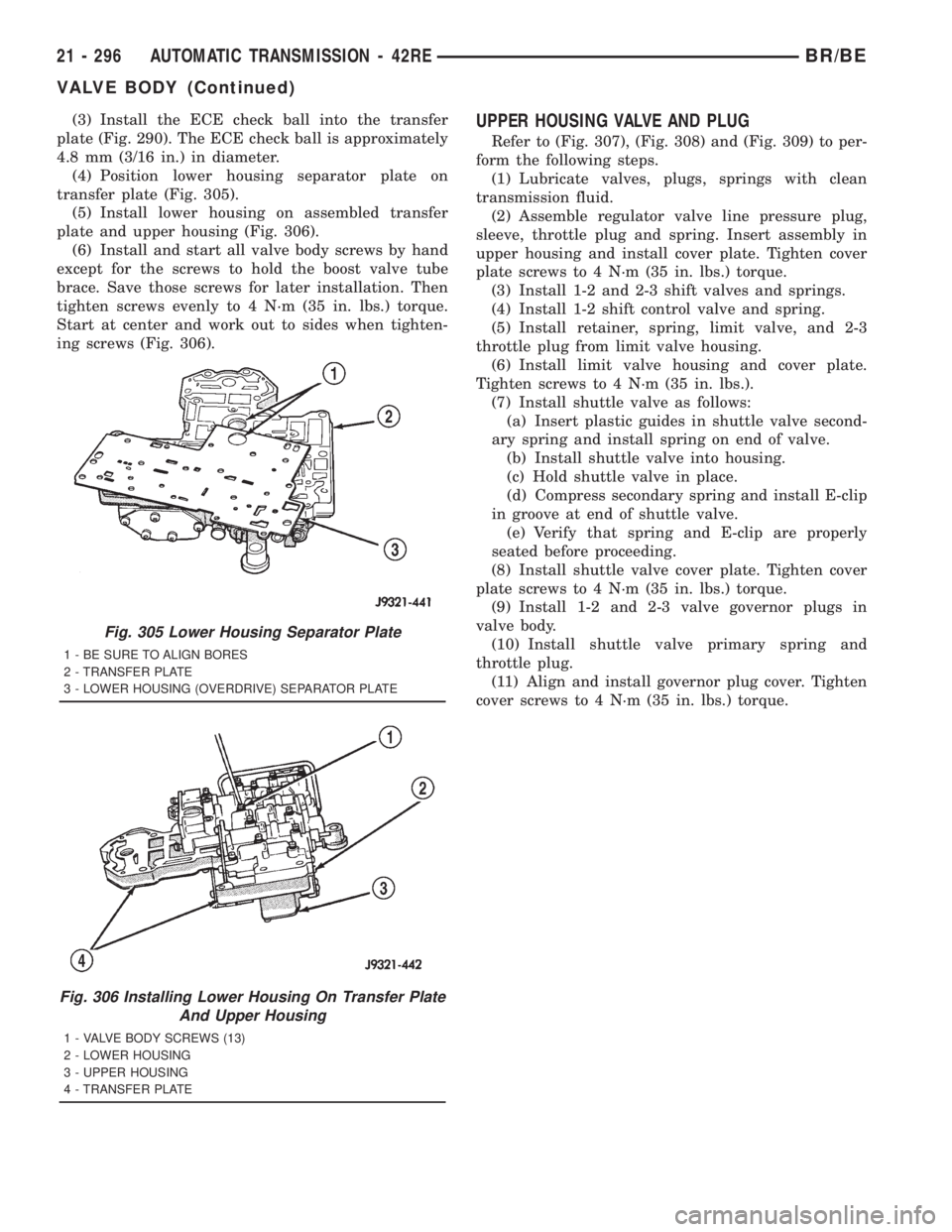
(4) Position lower housing separator plate on
transfer plate (Fig. 305).
(5) Install lower housing on assembled transfer
plate and upper housing (Fig. 306).
(6) Install and start all valve body screws by hand
except for the screws to hold the boost valve tube
brace. Save those screws for later installation. Then
tighten screws evenly to 4 N´m (35 in. lbs.) torque.
Start at center and work out to sides when tighten-
ing screws (Fig. 306).UPPER HOUSING VALVE AND PLUG
Refer to (Fig. 307), (Fig. 308) and (Fig. 309) to per-
form the following steps.
(1) Lubricate valves, plugs, springs with clean
transmission fluid.
(2) Assemble regulator valve line pressure plug,
sleeve, throttle plug and spring. Insert assembly in
upper housing and install cover plate. Tighten cover
plate screws to 4 N´m (35 in. lbs.) torque.
(3) Install 1-2 and 2-3 shift valves and springs.
(4) Install 1-2 shift control valve and spring.
(5) Install retainer, spring, limit valve, and 2-3
throttle plug from limit valve housing.
(6) Install limit valve housing and cover plate.
Tighten screws to 4 N´m (35 in. lbs.).
(7) Install shuttle valve as follows:
(a) Insert plastic guides in shuttle valve second-
ary spring and install spring on end of valve.
(b) Install shuttle valve into housing.
(c) Hold shuttle valve in place.
(d) Compress secondary spring and install E-clip
in groove at end of shuttle valve.
(e) Verify that spring and E-clip are properly
seated before proceeding.
(8) Install shuttle valve cover plate. Tighten cover
plate screws to 4 N´m (35 in. lbs.) torque.
(9) Install 1-2 and 2-3 valve governor plugs in
valve body.
(10) Install shuttle valve primary spring and
throttle plug.
(11) Align and install governor plug cover. Tighten
cover screws to 4 N´m (35 in. lbs.) torque.
Fig. 305 Lower Housing Separator Plate
1 - BE SURE TO ALIGN BORES
2 - TRANSFER PLATE
3 - LOWER HOUSING (OVERDRIVE) SEPARATOR PLATE
Fig. 306 Installing Lower Housing On Transfer Plate
And Upper Housing
1 - VALVE BODY SCREWS (13)
2 - LOWER HOUSING
3 - UPPER HOUSING
4 - TRANSFER PLATE
21 - 296 AUTOMATIC TRANSMISSION - 42REBR/BE
VALVE BODY (Continued)
Page 1932 of 2889
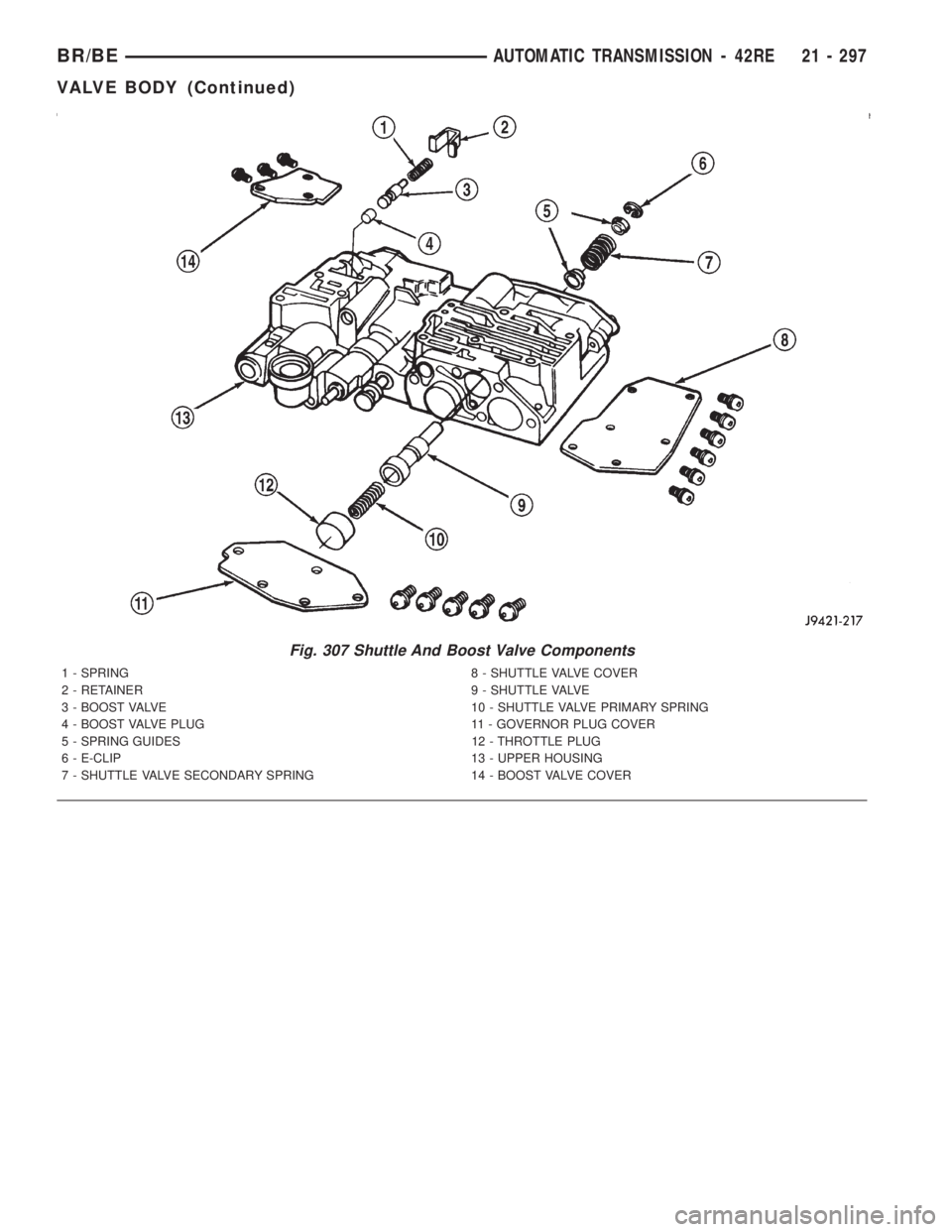
Fig. 307 Shuttle And Boost Valve Components
1 - SPRING 8 - SHUTTLE VALVE COVER
2 - RETAINER 9 - SHUTTLE VALVE
3 - BOOST VALVE 10 - SHUTTLE VALVE PRIMARY SPRING
4 - BOOST VALVE PLUG 11 - GOVERNOR PLUG COVER
5 - SPRING GUIDES 12 - THROTTLE PLUG
6 - E-CLIP 13 - UPPER HOUSING
7 - SHUTTLE VALVE SECONDARY SPRING 14 - BOOST VALVE COVER
BR/BEAUTOMATIC TRANSMISSION - 42RE 21 - 297
VALVE BODY (Continued)
Page 1933 of 2889
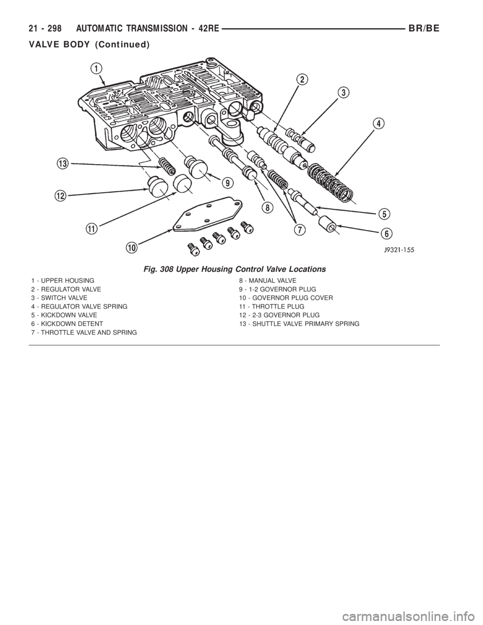
Fig. 308 Upper Housing Control Valve Locations
1 - UPPER HOUSING 8 - MANUAL VALVE
2 - REGULATOR VALVE 9 - 1-2 GOVERNOR PLUG
3 - SWITCH VALVE 10 - GOVERNOR PLUG COVER
4 - REGULATOR VALVE SPRING 11 - THROTTLE PLUG
5 - KICKDOWN VALVE 12 - 2-3 GOVERNOR PLUG
6 - KICKDOWN DETENT 13 - SHUTTLE VALVE PRIMARY SPRING
7 - THROTTLE VALVE AND SPRING
21 - 298 AUTOMATIC TRANSMISSION - 42REBR/BE
VALVE BODY (Continued)
Page 1934 of 2889
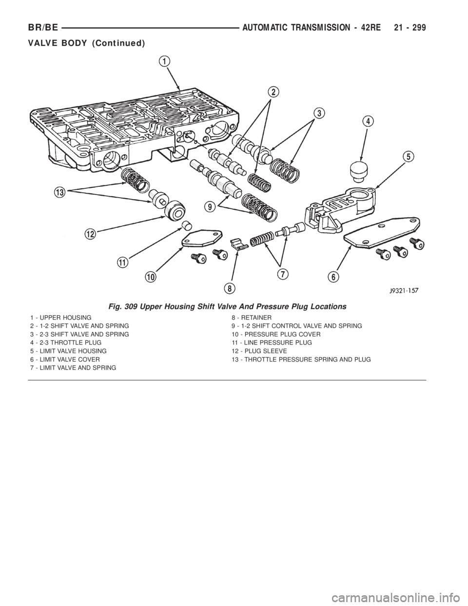
Fig. 309 Upper Housing Shift Valve And Pressure Plug Locations
1 - UPPER HOUSING 8 - RETAINER
2 - 1-2 SHIFT VALVE AND SPRING 9 - 1-2 SHIFT CONTROL VALVE AND SPRING
3 - 2-3 SHIFT VALVE AND SPRING 10 - PRESSURE PLUG COVER
4 - 2-3 THROTTLE PLUG 11 - LINE PRESSURE PLUG
5 - LIMIT VALVE HOUSING 12 - PLUG SLEEVE
6 - LIMIT VALVE COVER 13 - THROTTLE PRESSURE SPRING AND PLUG
7 - LIMIT VALVE AND SPRING
BR/BEAUTOMATIC TRANSMISSION - 42RE 21 - 299
VALVE BODY (Continued)
Page 1935 of 2889
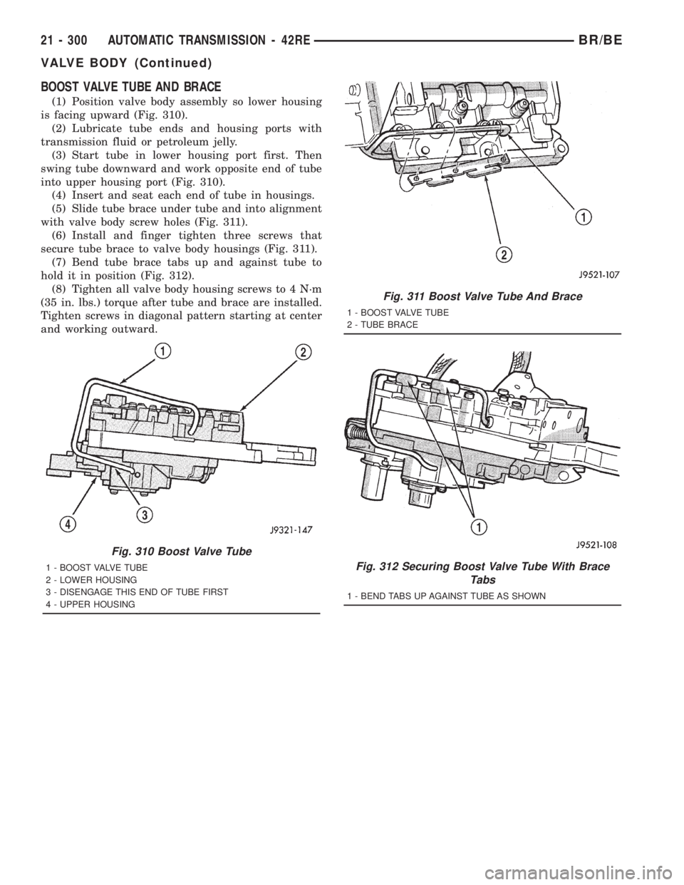
BOOST VALVE TUBE AND BRACE
(1) Position valve body assembly so lower housing
is facing upward (Fig. 310).
(2) Lubricate tube ends and housing ports with
transmission fluid or petroleum jelly.
(3) Start tube in lower housing port first. Then
swing tube downward and work opposite end of tube
into upper housing port (Fig. 310).
(4) Insert and seat each end of tube in housings.
(5) Slide tube brace under tube and into alignment
with valve body screw holes (Fig. 311).
(6) Install and finger tighten three screws that
secure tube brace to valve body housings (Fig. 311).
(7) Bend tube brace tabs up and against tube to
hold it in position (Fig. 312).
(8) Tighten all valve body housing screws to 4 N´m
(35 in. lbs.) torque after tube and brace are installed.
Tighten screws in diagonal pattern starting at center
and working outward.
Fig. 310 Boost Valve Tube
1 - BOOST VALVE TUBE
2 - LOWER HOUSING
3 - DISENGAGE THIS END OF TUBE FIRST
4 - UPPER HOUSING
Fig. 311 Boost Valve Tube And Brace
1 - BOOST VALVE TUBE
2 - TUBE BRACE
Fig. 312 Securing Boost Valve Tube With Brace
Tabs
1 - BEND TABS UP AGAINST TUBE AS SHOWN
21 - 300 AUTOMATIC TRANSMISSION - 42REBR/BE
VALVE BODY (Continued)
Page 1936 of 2889
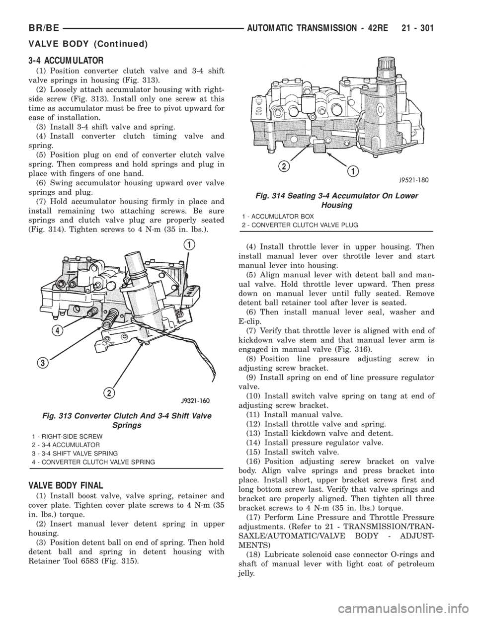
3-4 ACCUMULATOR
(1) Position converter clutch valve and 3-4 shift
valve springs in housing (Fig. 313).
(2) Loosely attach accumulator housing with right-
side screw (Fig. 313). Install only one screw at this
time as accumulator must be free to pivot upward for
ease of installation.
(3) Install 3-4 shift valve and spring.
(4) Install converter clutch timing valve and
spring.
(5) Position plug on end of converter clutch valve
spring. Then compress and hold springs and plug in
place with fingers of one hand.
(6) Swing accumulator housing upward over valve
springs and plug.
(7) Hold accumulator housing firmly in place and
install remaining two attaching screws. Be sure
springs and clutch valve plug are properly seated
(Fig. 314). Tighten screws to 4 N´m (35 in. lbs.).
VALVE BODY FINAL
(1) Install boost valve, valve spring, retainer and
cover plate. Tighten cover plate screws to 4 N´m (35
in. lbs.) torque.
(2) Insert manual lever detent spring in upper
housing.
(3) Position detent ball on end of spring. Then hold
detent ball and spring in detent housing with
Retainer Tool 6583 (Fig. 315).(4) Install throttle lever in upper housing. Then
install manual lever over throttle lever and start
manual lever into housing.
(5) Align manual lever with detent ball and man-
ual valve. Hold throttle lever upward. Then press
down on manual lever until fully seated. Remove
detent ball retainer tool after lever is seated.
(6) Then install manual lever seal, washer and
E-clip.
(7) Verify that throttle lever is aligned with end of
kickdown valve stem and that manual lever arm is
engaged in manual valve (Fig. 316).
(8) Position line pressure adjusting screw in
adjusting screw bracket.
(9) Install spring on end of line pressure regulator
valve.
(10) Install switch valve spring on tang at end of
adjusting screw bracket.
(11) Install manual valve.
(12) Install throttle valve and spring.
(13) Install kickdown valve and detent.
(14) Install pressure regulator valve.
(15) Install switch valve.
(16) Position adjusting screw bracket on valve
body. Align valve springs and press bracket into
place. Install short, upper bracket screws first and
long bottom screw last. Verify that valve springs and
bracket are properly aligned. Then tighten all three
bracket screws to 4 N´m (35 in. lbs.) torque.
(17) Perform Line Pressure and Throttle Pressure
adjustments. (Refer to 21 - TRANSMISSION/TRAN-
SAXLE/AUTOMATIC/VALVE BODY - ADJUST-
MENTS)
(18) Lubricate solenoid case connector O-rings and
shaft of manual lever with light coat of petroleum
jelly.
Fig. 313 Converter Clutch And 3-4 Shift Valve
Springs
1 - RIGHT-SIDE SCREW
2 - 3-4 ACCUMULATOR
3 - 3-4 SHIFT VALVE SPRING
4 - CONVERTER CLUTCH VALVE SPRING
Fig. 314 Seating 3-4 Accumulator On Lower
Housing
1 - ACCUMULATOR BOX
2 - CONVERTER CLUTCH VALVE PLUG
BR/BEAUTOMATIC TRANSMISSION - 42RE 21 - 301
VALVE BODY (Continued)
Page 1937 of 2889
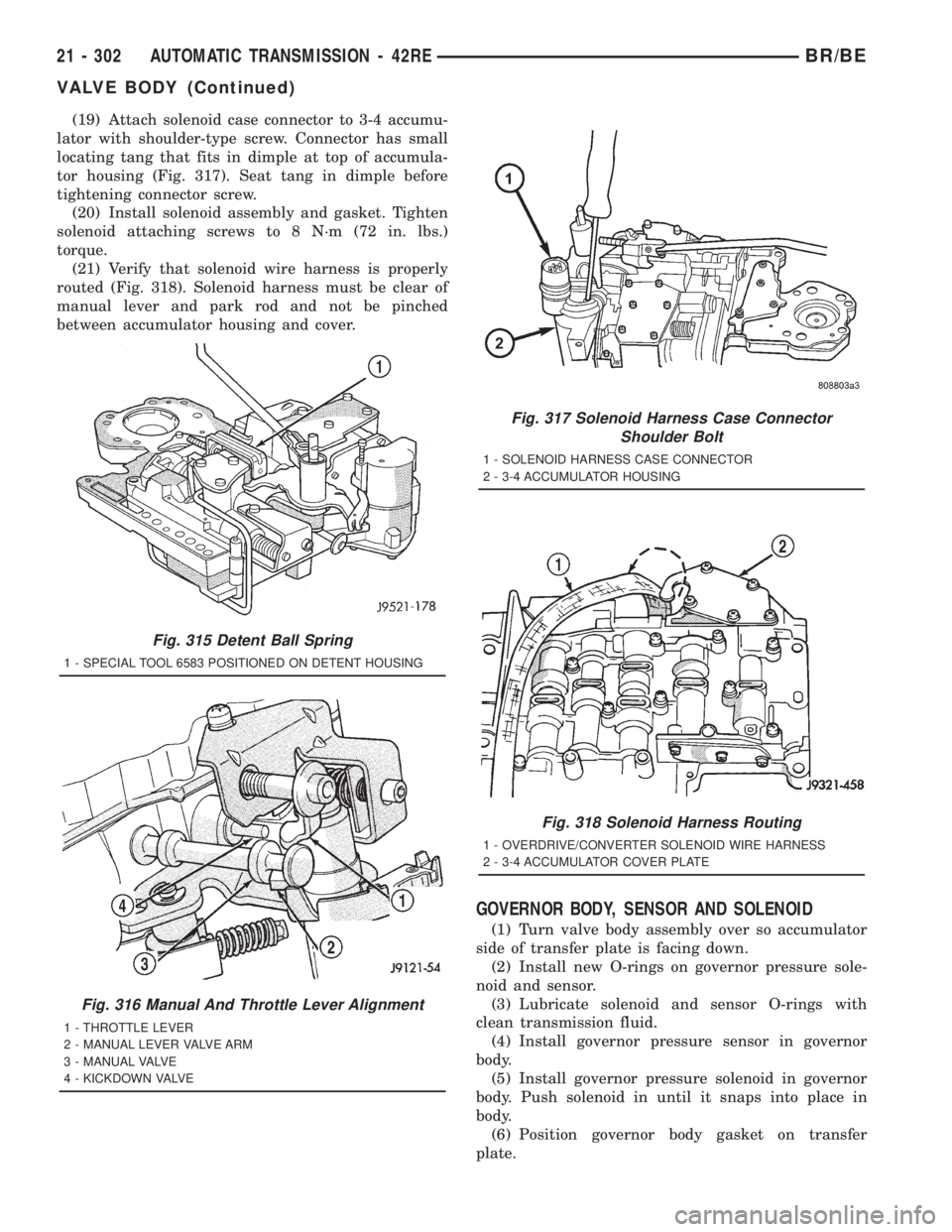
(19) Attach solenoid case connector to 3-4 accumu-
lator with shoulder-type screw. Connector has small
locating tang that fits in dimple at top of accumula-
tor housing (Fig. 317). Seat tang in dimple before
tightening connector screw.
(20) Install solenoid assembly and gasket. Tighten
solenoid attaching screws to 8 N´m (72 in. lbs.)
torque.
(21) Verify that solenoid wire harness is properly
routed (Fig. 318). Solenoid harness must be clear of
manual lever and park rod and not be pinched
between accumulator housing and cover.
GOVERNOR BODY, SENSOR AND SOLENOID
(1) Turn valve body assembly over so accumulator
side of transfer plate is facing down.
(2) Install new O-rings on governor pressure sole-
noid and sensor.
(3) Lubricate solenoid and sensor O-rings with
clean transmission fluid.
(4) Install governor pressure sensor in governor
body.
(5) Install governor pressure solenoid in governor
body. Push solenoid in until it snaps into place in
body.
(6) Position governor body gasket on transfer
plate.
Fig. 315 Detent Ball Spring
1 - SPECIAL TOOL 6583 POSITIONED ON DETENT HOUSING
Fig. 316 Manual And Throttle Lever Alignment
1 - THROTTLE LEVER
2 - MANUAL LEVER VALVE ARM
3 - MANUAL VALVE
4 - KICKDOWN VALVE
Fig. 317 Solenoid Harness Case Connector
Shoulder Bolt
1 - SOLENOID HARNESS CASE CONNECTOR
2 - 3-4 ACCUMULATOR HOUSING
Fig. 318 Solenoid Harness Routing
1 - OVERDRIVE/CONVERTER SOLENOID WIRE HARNESS
2 - 3-4 ACCUMULATOR COVER PLATE
21 - 302 AUTOMATIC TRANSMISSION - 42REBR/BE
VALVE BODY (Continued)
Page 1938 of 2889
(7) Install retainer plate on governor body and
around solenoid. Be sure solenoid connector is posi-
tioned in retainer cutout.
(8) Align screw holes in governor body and trans-
fer plate. Then install and tighten governor body
screws to 4 N´m (35 in. lbs.) torque.
(9) Connect harness wires to governor pressure
solenoid and governor pressure sensor.
(10) Install fluid filter and pan.
(11) Lower vehicle.
(12) Fill transmission with recommended fluid and
road test vehicle to verify repair.
INSTALLATION
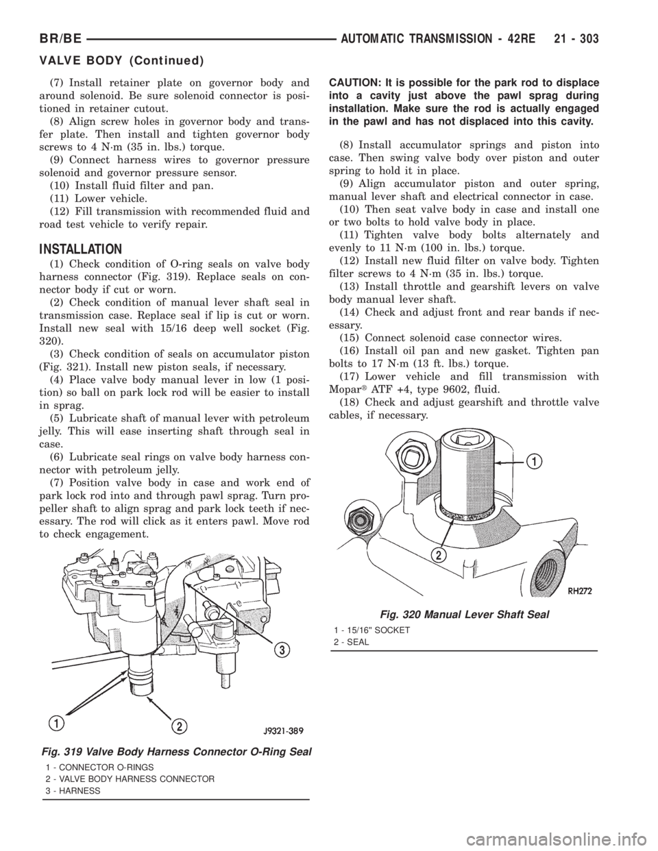
(1) Check condition of O-ring seals on valve body
harness connector (Fig. 319). Replace seals on con-
nector body if cut or worn.
(2) Check condition of manual lever shaft seal in
transmission case. Replace seal if lip is cut or worn.
Install new seal with 15/16 deep well socket (Fig.
320).
(3) Check condition of seals on accumulator piston
(Fig. 321). Install new piston seals, if necessary.
(4) Place valve body manual lever in low (1 posi-
tion) so ball on park lock rod will be easier to install
in sprag.
(5) Lubricate shaft of manual lever with petroleum
jelly. This will ease inserting shaft through seal in
case.
(6) Lubricate seal rings on valve body harness con-
nector with petroleum jelly.
(7) Position valve body in case and work end of
park lock rod into and through pawl sprag. Turn pro-
peller shaft to align sprag and park lock teeth if nec-
essary. The rod will click as it enters pawl. Move rod
to check engagement.CAUTION: It is possible for the park rod to displace
into a cavity just above the pawl sprag during
installation. Make sure the rod is actually engaged
in the pawl and has not displaced into this cavity.
(8) Install accumulator springs and piston into
case. Then swing valve body over piston and outer
spring to hold it in place.
(9) Align accumulator piston and outer spring,
manual lever shaft and electrical connector in case.
(10) Then seat valve body in case and install one
or two bolts to hold valve body in place.
(11) Tighten valve body bolts alternately and
evenly to 11 N´m (100 in. lbs.) torque.
(12) Install new fluid filter on valve body. Tighten
filter screws to 4 N´m (35 in. lbs.) torque.
(13) Install throttle and gearshift levers on valve
body manual lever shaft.
(14) Check and adjust front and rear bands if nec-
essary.
(15) Connect solenoid case connector wires.
(16) Install oil pan and new gasket. Tighten pan
bolts to 17 N´m (13 ft. lbs.) torque.
(17) Lower vehicle and fill transmission with
MopartATF +4, type 9602, fluid.
(18) Check and adjust gearshift and throttle valve
cables, if necessary.
Fig. 319 Valve Body Harness Connector O-Ring Seal
1 - CONNECTOR O-RINGS
2 - VALVE BODY HARNESS CONNECTOR
3 - HARNESS
Fig. 320 Manual Lever Shaft Seal
1 - 15/16©© SOCKET
2 - SEAL
BR/BEAUTOMATIC TRANSMISSION - 42RE 21 - 303
VALVE BODY (Continued)
Page 1939 of 2889
ADJUSTMENTS - VALVE BODY
CONTROL PRESSURE ADJUSTMENTS
There are two control pressure adjustments on the
valve body;
²Line Pressure
²Throttle Pressure
Line and throttle pressures are interdependent
because each affects shift quality and timing. As a
result, both adjustments must be performed properly
and in the correct sequence. Adjust line pressure first
and throttle pressure last.
LINE PRESSURE ADJUSTMENT
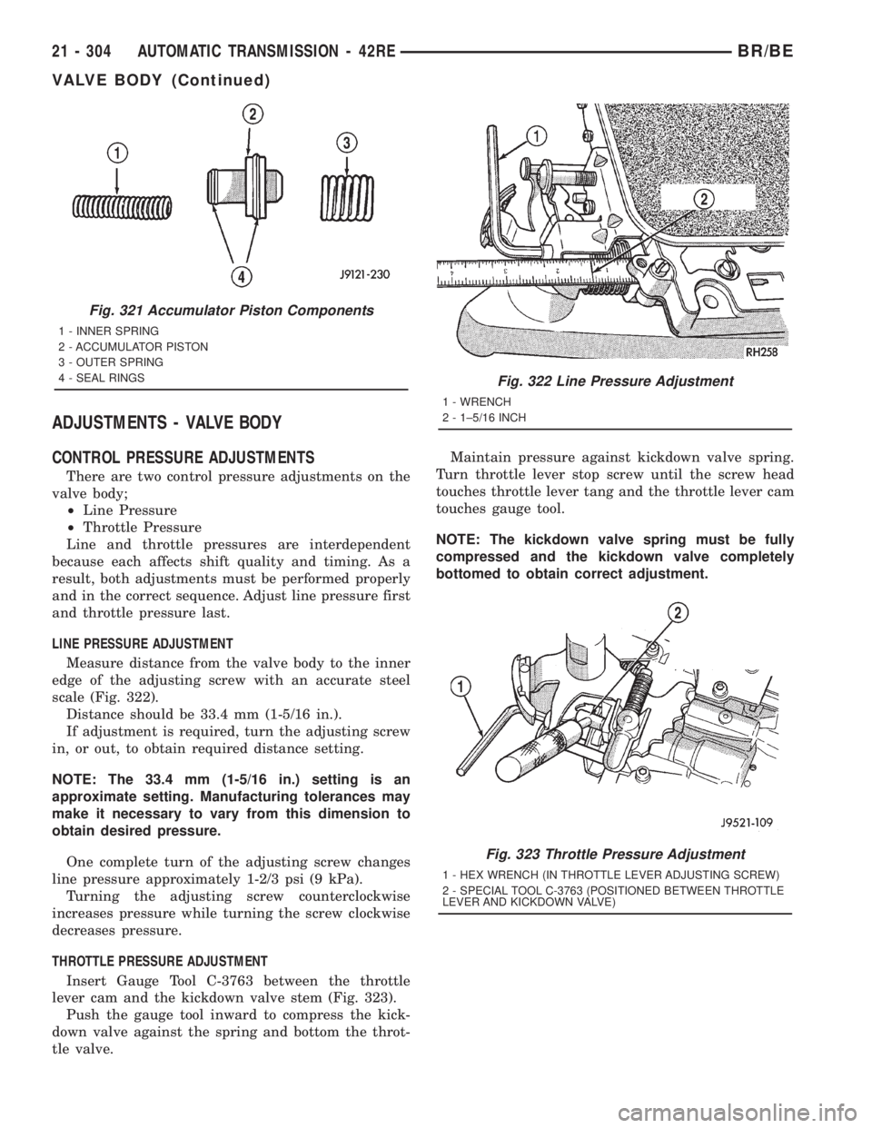
Measure distance from the valve body to the inner
edge of the adjusting screw with an accurate steel
scale (Fig. 322).
Distance should be 33.4 mm (1-5/16 in.).
If adjustment is required, turn the adjusting screw
in, or out, to obtain required distance setting.
NOTE: The 33.4 mm (1-5/16 in.) setting is an
approximate setting. Manufacturing tolerances may
make it necessary to vary from this dimension to
obtain desired pressure.
One complete turn of the adjusting screw changes
line pressure approximately 1-2/3 psi (9 kPa).
Turning the adjusting screw counterclockwise
increases pressure while turning the screw clockwise
decreases pressure.
THROTTLE PRESSURE ADJUSTMENT
Insert Gauge Tool C-3763 between the throttle
lever cam and the kickdown valve stem (Fig. 323).
Push the gauge tool inward to compress the kick-
down valve against the spring and bottom the throt-
tle valve.Maintain pressure against kickdown valve spring.
Turn throttle lever stop screw until the screw head
touches throttle lever tang and the throttle lever cam
touches gauge tool.
NOTE: The kickdown valve spring must be fully
compressed and the kickdown valve completely
bottomed to obtain correct adjustment.
Fig. 321 Accumulator Piston Components
1 - INNER SPRING
2 - ACCUMULATOR PISTON
3 - OUTER SPRING
4 - SEAL RINGS
Fig. 322 Line Pressure Adjustment
1 - WRENCH
2 - 1±5/16 INCH
Fig. 323 Throttle Pressure Adjustment
1 - HEX WRENCH (IN THROTTLE LEVER ADJUSTING SCREW)
2 - SPECIAL TOOL C-3763 (POSITIONED BETWEEN THROTTLE
LEVER AND KICKDOWN VALVE)
21 - 304 AUTOMATIC TRANSMISSION - 42REBR/BE
VALVE BODY (Continued)
Page 1940 of 2889
AUTOMATIC TRANSMISSION - 44RE
TABLE OF CONTENTS
page page
AUTOMATIC TRANSMISSION - 44RE
DESCRIPTION..........................306
OPERATION............................308
DIAGNOSIS AND TESTING................314
AUTOMATIC TRANSMISSION.............314
PRELIMINARY........................314
ROAD TESTING.......................314
HYDRAULIC PRESSURE TEST...........315
AIR CHECKING TRANSMISSION CLUTCH
AND BAND OPERATION.................318
CONVERTER HOUSING FLUID LEAK......319
DIAGNOSIS CHARTS...................320
STANDARD PROCEDURE.................330
ALUMINUM THREAD REPAIR.............330
REMOVAL.............................330
DISASSEMBLY..........................331
CLEANING.............................336
INSPECTION...........................337
ASSEMBLY............................337
INSTALLATION..........................344
SCHEMATICS AND DIAGRAMS.............345
SPECIFICATIONS........................357
SPECIAL TOOLS........................359
ACCUMULATOR
DESCRIPTION..........................362
OPERATION............................362
INSPECTION...........................363
BANDS
DESCRIPTION..........................363
OPERATION............................364
ADJUSTMENTS.........................364
ELECTRONIC GOVERNOR
DESCRIPTION..........................365
OPERATION............................365
REMOVAL.............................367
INSTALLATION..........................367
EXTENSION HOUSING BUSHING
REMOVAL.............................369
INSTALLATION..........................369
EXTENSION HOUSING SEAL
REMOVAL.............................369
INSTALLATION..........................369
FLUID AND FILTER
DIAGNOSIS AND TESTING................370
EFFECTS OF INCORRECT FLUID LEVEL . . . 370
CAUSES OF BURNT FLUID..............370
FLUID CONTAMINATION................370
STANDARD PROCEDURE.................370
FLUID LEVEL CHECK...................370FLUID AND FILTER REPLACEMENT.......372
TRANSMISSION FILL...................372
FRONT CLUTCH
DESCRIPTION..........................373
OPERATION............................373
DISASSEMBLY..........................373
INSPECTION...........................376
ASSEMBLY............................376
FRONT SERVO
DESCRIPTION..........................377
OPERATION............................377
DISASSEMBLY..........................378
CLEANING.............................378
INSPECTION...........................378
ASSEMBLY............................379
OIL PUMP
DESCRIPTION..........................379
OPERATION............................379
STANDARD PROCEDURE.................379
OIL PUMP VOLUME CHECK..............379
DISASSEMBLY..........................380
CLEANING.............................381
INSPECTION...........................382
ASSEMBLY............................382
OUTPUT SHAFT FRONT BEARING
REMOVAL.............................384
INSTALLATION..........................384
OUTPUT SHAFT REAR BEARING
REMOVAL.............................384
INSTALLATION..........................384
OVERDRIVE CLUTCH
DESCRIPTION..........................385
OPERATION............................385
OVERDRIVE SWITCH
DESCRIPTION..........................385
OPERATION............................385
DIAGNOSIS AND TESTING................386
OVERDRIVE ELECTRICAL CONTROLS.....386
REMOVAL.............................386
INSTALLATION..........................386
OVERDRIVE UNIT
REMOVAL.............................387
DISASSEMBLY..........................387
CLEANING.............................394
INSPECTION...........................394
ASSEMBLY............................395
INSTALLATION..........................404
BR/BEAUTOMATIC TRANSMISSION - 44RE 21 - 305