DODGE RAM 2001 Service Repair Manual
Manufacturer: DODGE, Model Year: 2001, Model line: RAM, Model: DODGE RAM 2001Pages: 2889, PDF Size: 68.07 MB
Page 1891 of 2889
TORQUE CONVERTER
DESCRIPTION
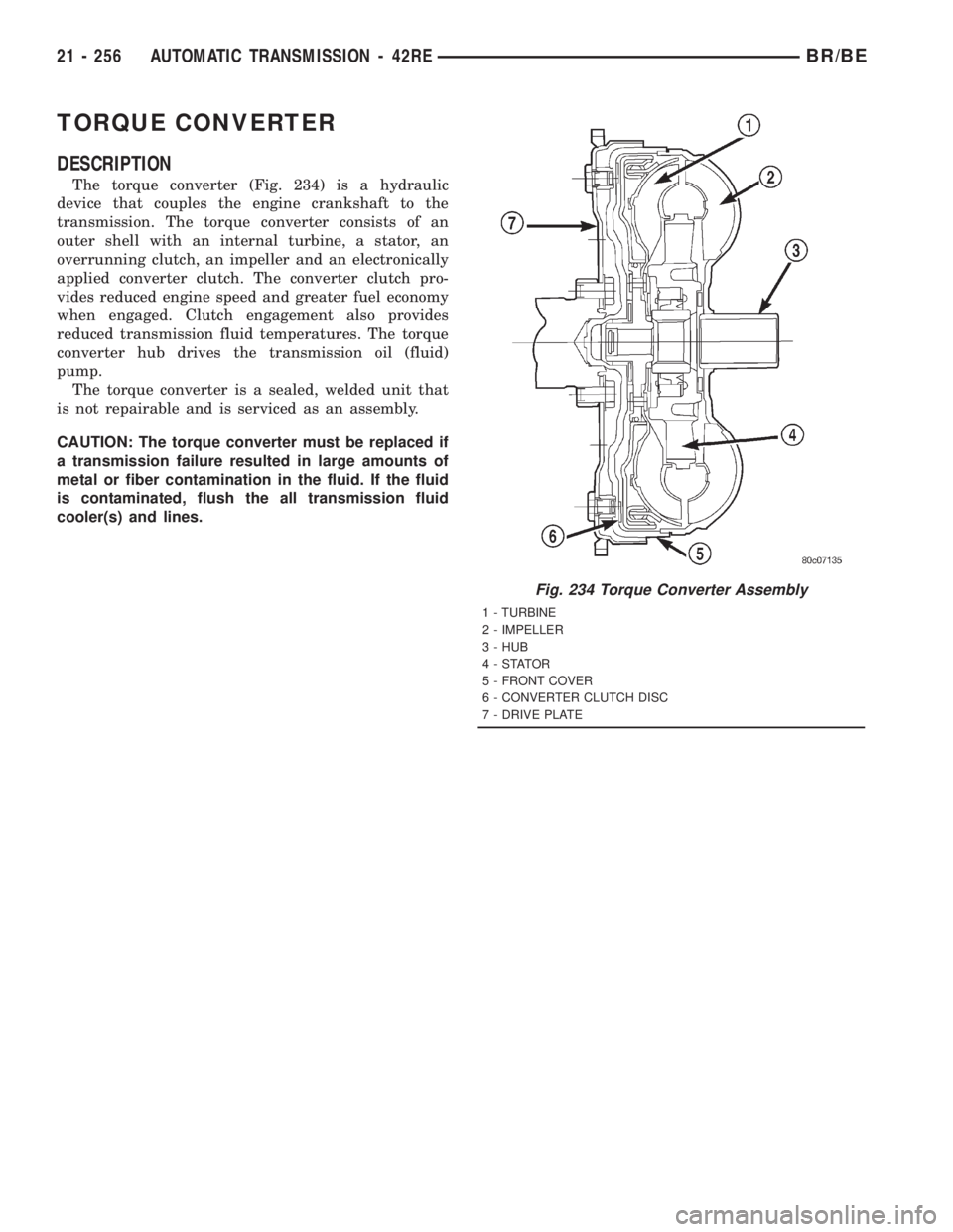
The torque converter (Fig. 234) is a hydraulic
device that couples the engine crankshaft to the
transmission. The torque converter consists of an
outer shell with an internal turbine, a stator, an
overrunning clutch, an impeller and an electronically
applied converter clutch. The converter clutch pro-
vides reduced engine speed and greater fuel economy
when engaged. Clutch engagement also provides
reduced transmission fluid temperatures. The torque
converter hub drives the transmission oil (fluid)
pump.
The torque converter is a sealed, welded unit that
is not repairable and is serviced as an assembly.
CAUTION: The torque converter must be replaced if
a transmission failure resulted in large amounts of
metal or fiber contamination in the fluid. If the fluid
is contaminated, flush the all transmission fluid
cooler(s) and lines.
Fig. 234 Torque Converter Assembly
1 - TURBINE
2 - IMPELLER
3 - HUB
4-STATOR
5 - FRONT COVER
6 - CONVERTER CLUTCH DISC
7 - DRIVE PLATE
21 - 256 AUTOMATIC TRANSMISSION - 42REBR/BE
Page 1892 of 2889
IMPELLER
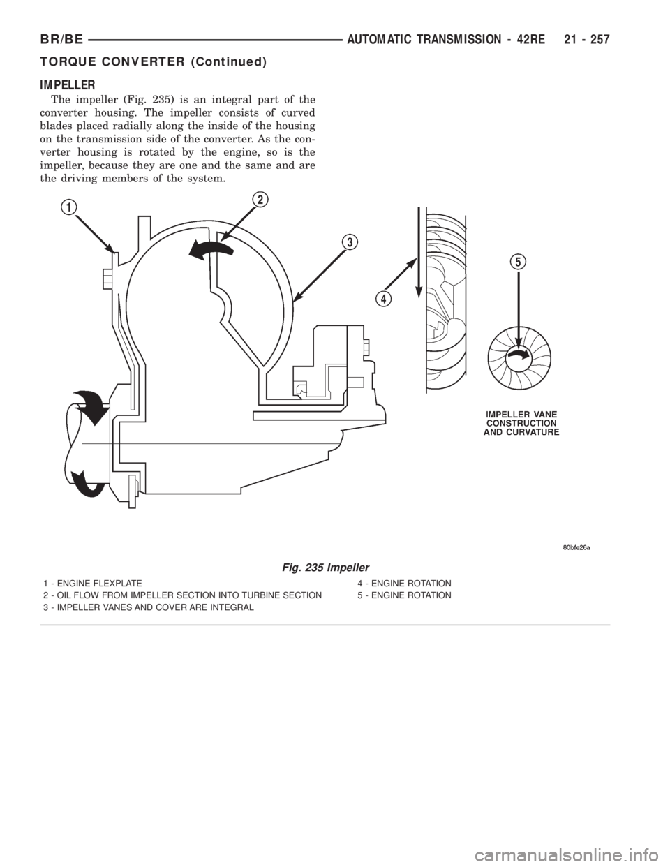
The impeller (Fig. 235) is an integral part of the
converter housing. The impeller consists of curved
blades placed radially along the inside of the housing
on the transmission side of the converter. As the con-
verter housing is rotated by the engine, so is the
impeller, because they are one and the same and are
the driving members of the system.
Fig. 235 Impeller
1 - ENGINE FLEXPLATE 4 - ENGINE ROTATION
2 - OIL FLOW FROM IMPELLER SECTION INTO TURBINE SECTION 5 - ENGINE ROTATION
3 - IMPELLER VANES AND COVER ARE INTEGRAL
BR/BEAUTOMATIC TRANSMISSION - 42RE 21 - 257
TORQUE CONVERTER (Continued)
Page 1893 of 2889
TURBINE
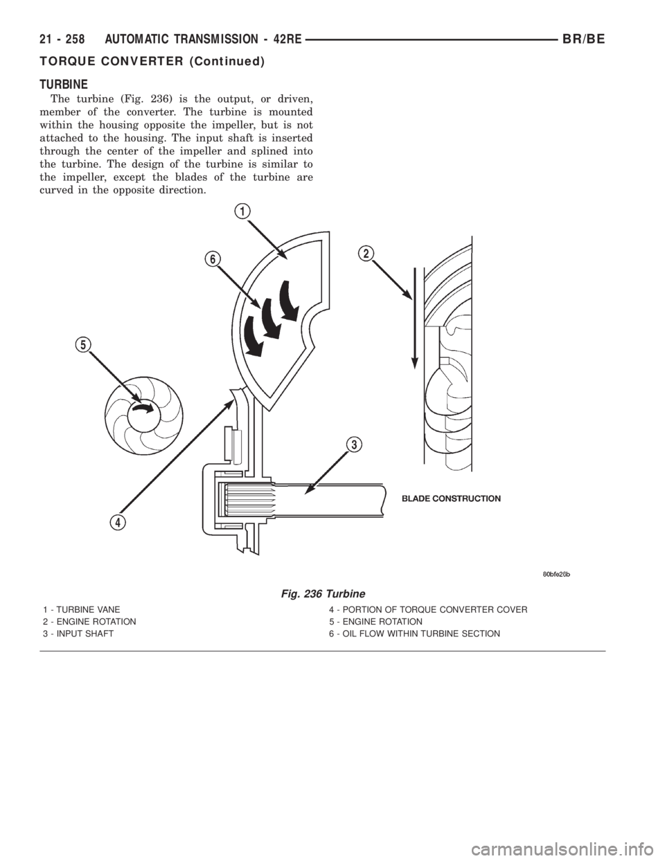
The turbine (Fig. 236) is the output, or driven,
member of the converter. The turbine is mounted
within the housing opposite the impeller, but is not
attached to the housing. The input shaft is inserted
through the center of the impeller and splined into
the turbine. The design of the turbine is similar to
the impeller, except the blades of the turbine are
curved in the opposite direction.
Fig. 236 Turbine
1 - TURBINE VANE 4 - PORTION OF TORQUE CONVERTER COVER
2 - ENGINE ROTATION 5 - ENGINE ROTATION
3 - INPUT SHAFT 6 - OIL FLOW WITHIN TURBINE SECTION
21 - 258 AUTOMATIC TRANSMISSION - 42REBR/BE
TORQUE CONVERTER (Continued)
Page 1894 of 2889
STATOR
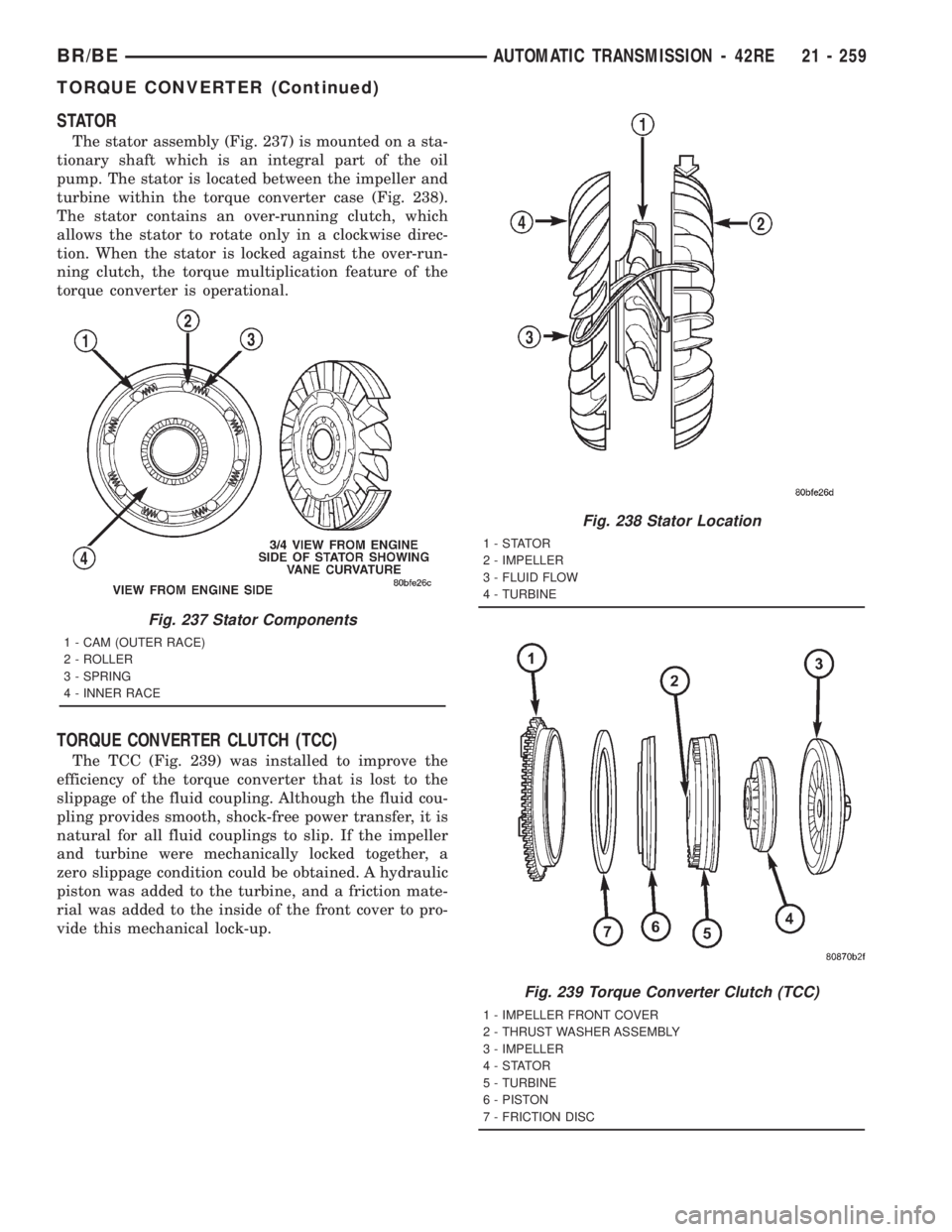
The stator assembly (Fig. 237) is mounted on a sta-
tionary shaft which is an integral part of the oil
pump. The stator is located between the impeller and
turbine within the torque converter case (Fig. 238).
The stator contains an over-running clutch, which
allows the stator to rotate only in a clockwise direc-
tion. When the stator is locked against the over-run-
ning clutch, the torque multiplication feature of the
torque converter is operational.
TORQUE CONVERTER CLUTCH (TCC)
The TCC (Fig. 239) was installed to improve the
efficiency of the torque converter that is lost to the
slippage of the fluid coupling. Although the fluid cou-
pling provides smooth, shock-free power transfer, it is
natural for all fluid couplings to slip. If the impeller
and turbine were mechanically locked together, a
zero slippage condition could be obtained. A hydraulic
piston was added to the turbine, and a friction mate-
rial was added to the inside of the front cover to pro-
vide this mechanical lock-up.
Fig. 237 Stator Components
1 - CAM (OUTER RACE)
2 - ROLLER
3 - SPRING
4 - INNER RACE
Fig. 238 Stator Location
1-STATOR
2 - IMPELLER
3 - FLUID FLOW
4 - TURBINE
Fig. 239 Torque Converter Clutch (TCC)
1 - IMPELLER FRONT COVER
2 - THRUST WASHER ASSEMBLY
3 - IMPELLER
4-STATOR
5 - TURBINE
6 - PISTON
7 - FRICTION DISC
BR/BEAUTOMATIC TRANSMISSION - 42RE 21 - 259
TORQUE CONVERTER (Continued)
Page 1895 of 2889
OPERATION
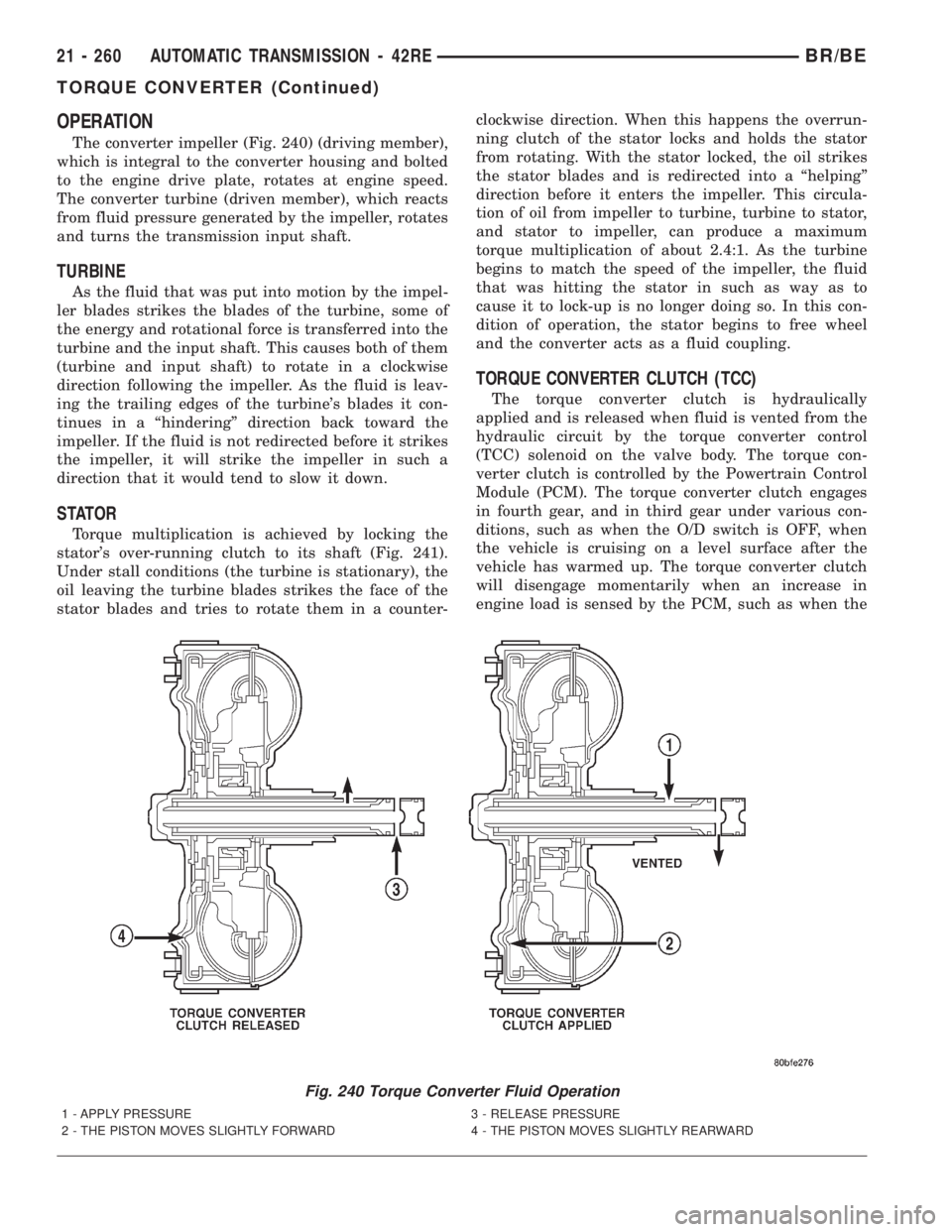
The converter impeller (Fig. 240) (driving member),
which is integral to the converter housing and bolted
to the engine drive plate, rotates at engine speed.
The converter turbine (driven member), which reacts
from fluid pressure generated by the impeller, rotates
and turns the transmission input shaft.
TURBINE
As the fluid that was put into motion by the impel-
ler blades strikes the blades of the turbine, some of
the energy and rotational force is transferred into the
turbine and the input shaft. This causes both of them
(turbine and input shaft) to rotate in a clockwise
direction following the impeller. As the fluid is leav-
ing the trailing edges of the turbine's blades it con-
tinues in a ªhinderingº direction back toward the
impeller. If the fluid is not redirected before it strikes
the impeller, it will strike the impeller in such a
direction that it would tend to slow it down.
STATOR
Torque multiplication is achieved by locking the
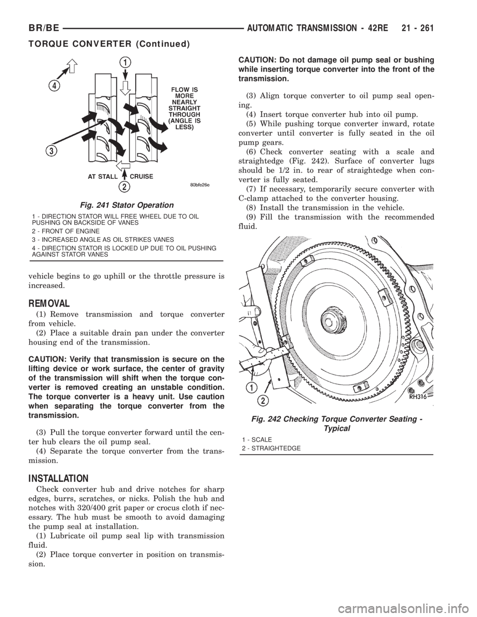
stator's over-running clutch to its shaft (Fig. 241).
Under stall conditions (the turbine is stationary), the
oil leaving the turbine blades strikes the face of the
stator blades and tries to rotate them in a counter-clockwise direction. When this happens the overrun-
ning clutch of the stator locks and holds the stator
from rotating. With the stator locked, the oil strikes
the stator blades and is redirected into a ªhelpingº
direction before it enters the impeller. This circula-
tion of oil from impeller to turbine, turbine to stator,
and stator to impeller, can produce a maximum
torque multiplication of about 2.4:1. As the turbine
begins to match the speed of the impeller, the fluid
that was hitting the stator in such as way as to
cause it to lock-up is no longer doing so. In this con-
dition of operation, the stator begins to free wheel
and the converter acts as a fluid coupling.
TORQUE CONVERTER CLUTCH (TCC)
The torque converter clutch is hydraulically
applied and is released when fluid is vented from the
hydraulic circuit by the torque converter control
(TCC) solenoid on the valve body. The torque con-
verter clutch is controlled by the Powertrain Control
Module (PCM). The torque converter clutch engages
in fourth gear, and in third gear under various con-
ditions, such as when the O/D switch is OFF, when
the vehicle is cruising on a level surface after the
vehicle has warmed up. The torque converter clutch
will disengage momentarily when an increase in
engine load is sensed by the PCM, such as when the
Fig. 240 Torque Converter Fluid Operation
1 - APPLY PRESSURE 3 - RELEASE PRESSURE
2 - THE PISTON MOVES SLIGHTLY FORWARD 4 - THE PISTON MOVES SLIGHTLY REARWARD
21 - 260 AUTOMATIC TRANSMISSION - 42REBR/BE
TORQUE CONVERTER (Continued)
Page 1896 of 2889
vehicle begins to go uphill or the throttle pressure is
increased.
REMOVAL
(1) Remove transmission and torque converter
from vehicle.
(2) Place a suitable drain pan under the converter
housing end of the transmission.
CAUTION: Verify that transmission is secure on the
lifting device or work surface, the center of gravity
of the transmission will shift when the torque con-
verter is removed creating an unstable condition.
The torque converter is a heavy unit. Use caution
when separating the torque converter from the
transmission.
(3) Pull the torque converter forward until the cen-
ter hub clears the oil pump seal.
(4) Separate the torque converter from the trans-
mission.
INSTALLATION
Check converter hub and drive notches for sharp
edges, burrs, scratches, or nicks. Polish the hub and
notches with 320/400 grit paper or crocus cloth if nec-
essary. The hub must be smooth to avoid damaging
the pump seal at installation.
(1) Lubricate oil pump seal lip with transmission
fluid.
(2) Place torque converter in position on transmis-
sion.CAUTION: Do not damage oil pump seal or bushing
while inserting torque converter into the front of the
transmission.
(3) Align torque converter to oil pump seal open-
ing.
(4) Insert torque converter hub into oil pump.
(5) While pushing torque converter inward, rotate
converter until converter is fully seated in the oil
pump gears.
(6) Check converter seating with a scale and
straightedge (Fig. 242). Surface of converter lugs
should be 1/2 in. to rear of straightedge when con-
verter is fully seated.
(7) If necessary, temporarily secure converter with
C-clamp attached to the converter housing.
(8) Install the transmission in the vehicle.
(9) Fill the transmission with the recommended
fluid.
Fig. 241 Stator Operation
1 - DIRECTION STATOR WILL FREE WHEEL DUE TO OIL
PUSHING ON BACKSIDE OF VANES
2 - FRONT OF ENGINE
3 - INCREASED ANGLE AS OIL STRIKES VANES
4 - DIRECTION STATOR IS LOCKED UP DUE TO OIL PUSHING
AGAINST STATOR VANES
Fig. 242 Checking Torque Converter Seating -
Typical
1 - SCALE
2 - STRAIGHTEDGE
BR/BEAUTOMATIC TRANSMISSION - 42RE 21 - 261
TORQUE CONVERTER (Continued)
Page 1897 of 2889
TORQUE CONVERTER
DRAINBACK VALVE
DESCRIPTION
The drainback valve is located in the transmission
cooler outlet (pressure) line.
OPERATION
The valve prevents fluid from draining from the
converter into the cooler and lines when the vehicle
is shut down for lengthy periods. Production valves
have a hose nipple at one end, while the opposite end
is threaded for a flare fitting. All valves have an
arrow (or similar mark) to indicate direction of flow
through the valve.
STANDARD PROCEDURE - TORQUE
CONVERTER DRAINBACK VALVE
The converter drainback check valve is located in
the cooler outlet (pressure) line near the radiator
tank. The valve prevents fluid drainback when the
vehicle is parked for lengthy periods. The valve check
ball is spring loaded and has an opening pressure of
approximately 2 psi.
The valve is serviced as an assembly; it is not
repairable. Do not clean the valve if restricted, or
contaminated by sludge, or debris. If the valve fails,
or if a transmission malfunction occurs that gener-
ates significant amounts of sludge and/or clutch par-
ticles and metal shavings, the valve must be
replaced.
The valve must be removed whenever the cooler
and lines are reverse flushed. The valve can be flow
tested when necessary. The procedure is exactly the
same as for flow testing a cooler.
If the valve is restricted, installed backwards, or in
the wrong line, it will cause an overheating condition
and possible transmission failure.
CAUTION: The drainback valve is a one-way flow
device. It must be properly oriented in terms of flow
direction for the cooler to function properly. The
valve must be installed in the pressure line. Other-
wise flow will be blocked and would cause an over-
heating condition and eventual transmission failure.
TRANSMISSION
TEMPERATURE SENSOR
DESCRIPTION
Transmission fluid temperature readings are sup-
plied to the transmission control module by the ther-
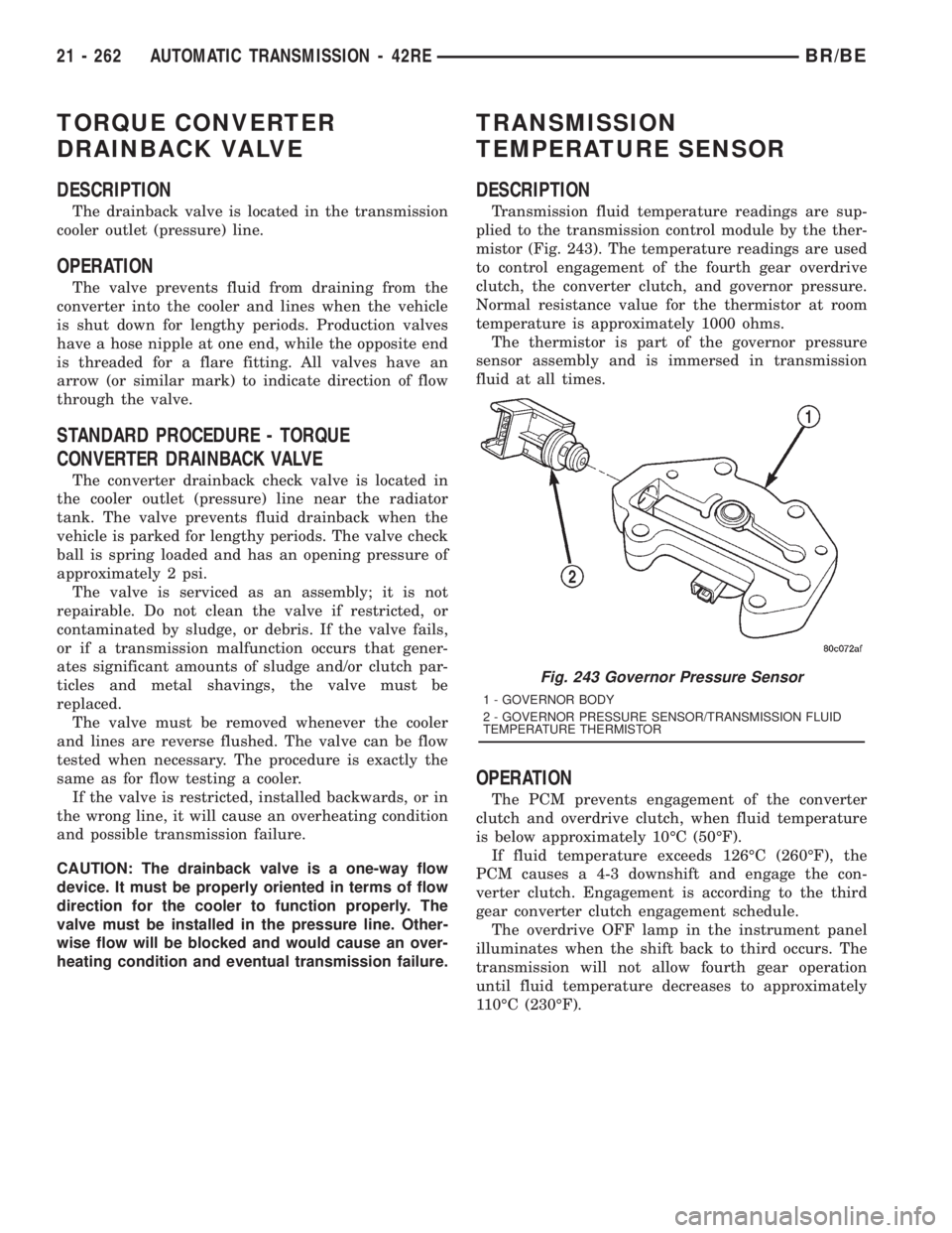
mistor (Fig. 243). The temperature readings are used
to control engagement of the fourth gear overdrive
clutch, the converter clutch, and governor pressure.
Normal resistance value for the thermistor at room
temperature is approximately 1000 ohms.
The thermistor is part of the governor pressure
sensor assembly and is immersed in transmission
fluid at all times.
OPERATION
The PCM prevents engagement of the converter
clutch and overdrive clutch, when fluid temperature
is below approximately 10ÉC (50ÉF).
If fluid temperature exceeds 126ÉC (260ÉF), the
PCM causes a 4-3 downshift and engage the con-
verter clutch. Engagement is according to the third
gear converter clutch engagement schedule.
The overdrive OFF lamp in the instrument panel
illuminates when the shift back to third occurs. The
transmission will not allow fourth gear operation
until fluid temperature decreases to approximately
110ÉC (230ÉF).
Fig. 243 Governor Pressure Sensor
1 - GOVERNOR BODY
2 - GOVERNOR PRESSURE SENSOR/TRANSMISSION FLUID
TEMPERATURE THERMISTOR
21 - 262 AUTOMATIC TRANSMISSION - 42REBR/BE
Page 1898 of 2889
VALVE BODY
DESCRIPTION
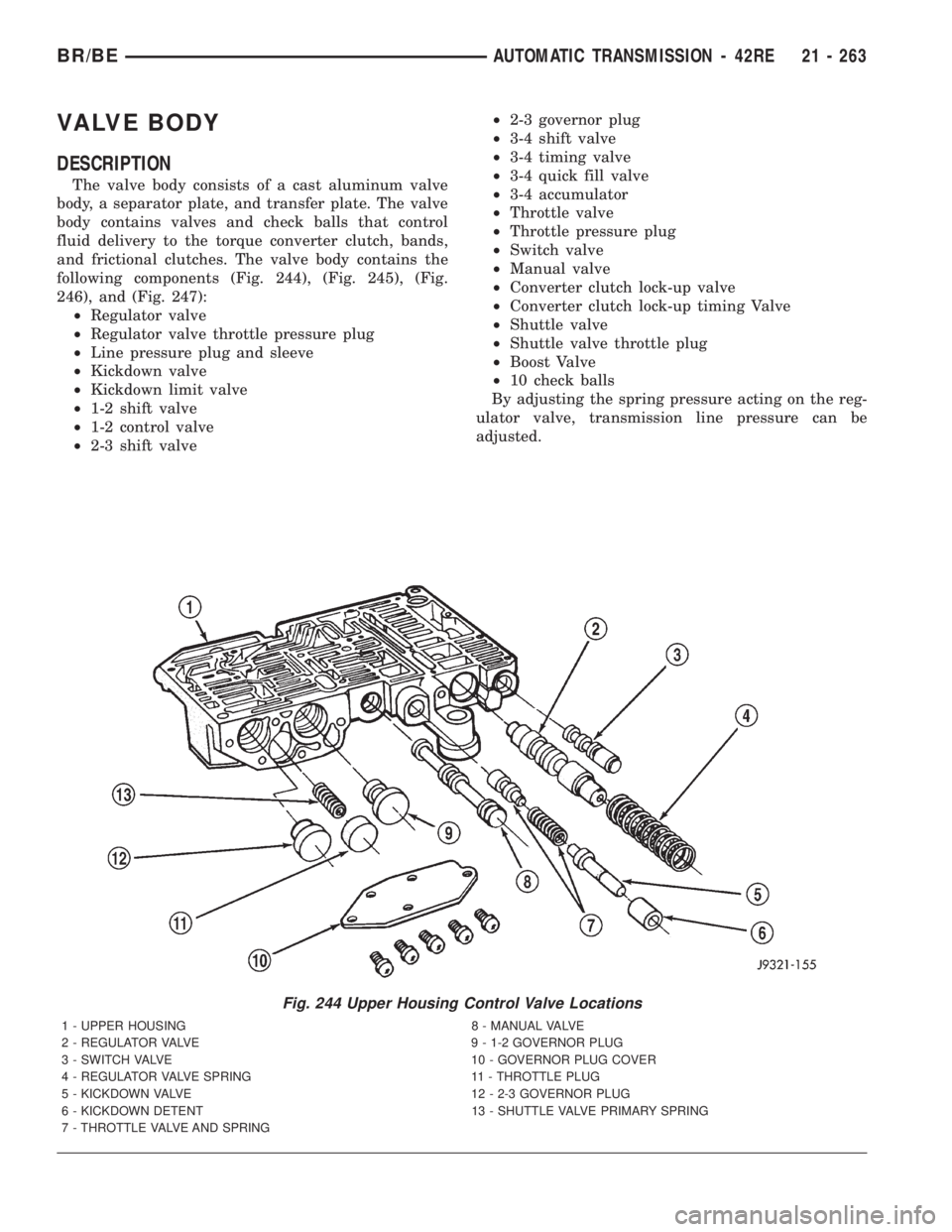
The valve body consists of a cast aluminum valve
body, a separator plate, and transfer plate. The valve
body contains valves and check balls that control
fluid delivery to the torque converter clutch, bands,
and frictional clutches. The valve body contains the
following components (Fig. 244), (Fig. 245), (Fig.
246), and (Fig. 247):
²Regulator valve
²Regulator valve throttle pressure plug
²Line pressure plug and sleeve
²Kickdown valve
²Kickdown limit valve
²1-2 shift valve
²1-2 control valve
²2-3 shift valve²2-3 governor plug
²3-4 shift valve
²3-4 timing valve
²3-4 quick fill valve
²3-4 accumulator
²Throttle valve
²Throttle pressure plug
²Switch valve
²Manual valve
²Converter clutch lock-up valve
²Converter clutch lock-up timing Valve
²Shuttle valve
²Shuttle valve throttle plug
²Boost Valve
²10 check balls
By adjusting the spring pressure acting on the reg-
ulator valve, transmission line pressure can be
adjusted.
Fig. 244 Upper Housing Control Valve Locations
1 - UPPER HOUSING 8 - MANUAL VALVE
2 - REGULATOR VALVE 9 - 1-2 GOVERNOR PLUG
3 - SWITCH VALVE 10 - GOVERNOR PLUG COVER
4 - REGULATOR VALVE SPRING 11 - THROTTLE PLUG
5 - KICKDOWN VALVE 12 - 2-3 GOVERNOR PLUG
6 - KICKDOWN DETENT 13 - SHUTTLE VALVE PRIMARY SPRING
7 - THROTTLE VALVE AND SPRING
BR/BEAUTOMATIC TRANSMISSION - 42RE 21 - 263
Page 1899 of 2889
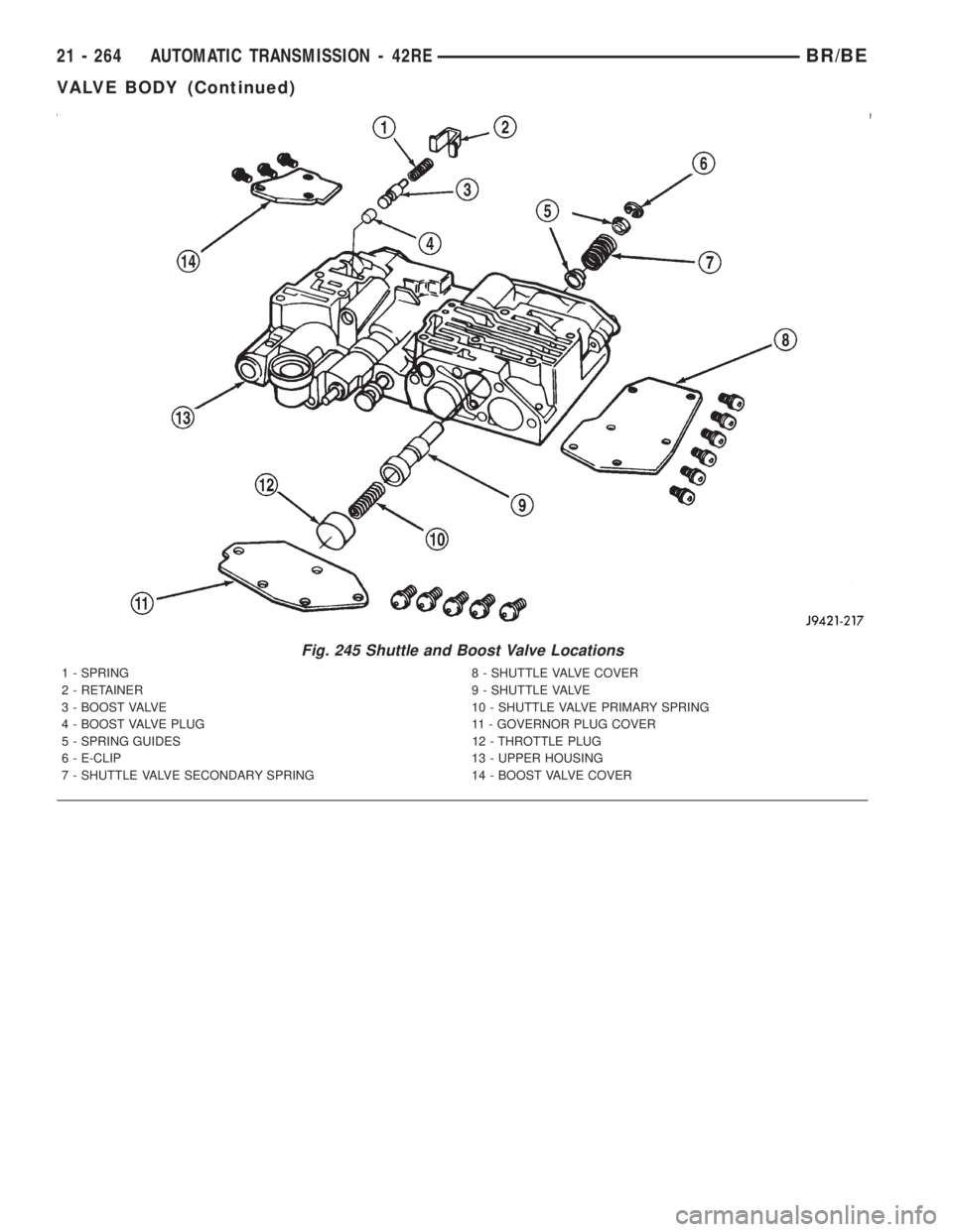
Fig. 245 Shuttle and Boost Valve Locations
1 - SPRING 8 - SHUTTLE VALVE COVER
2 - RETAINER 9 - SHUTTLE VALVE
3 - BOOST VALVE 10 - SHUTTLE VALVE PRIMARY SPRING
4 - BOOST VALVE PLUG 11 - GOVERNOR PLUG COVER
5 - SPRING GUIDES 12 - THROTTLE PLUG
6 - E-CLIP 13 - UPPER HOUSING
7 - SHUTTLE VALVE SECONDARY SPRING 14 - BOOST VALVE COVER
21 - 264 AUTOMATIC TRANSMISSION - 42REBR/BE
VALVE BODY (Continued)
Page 1900 of 2889
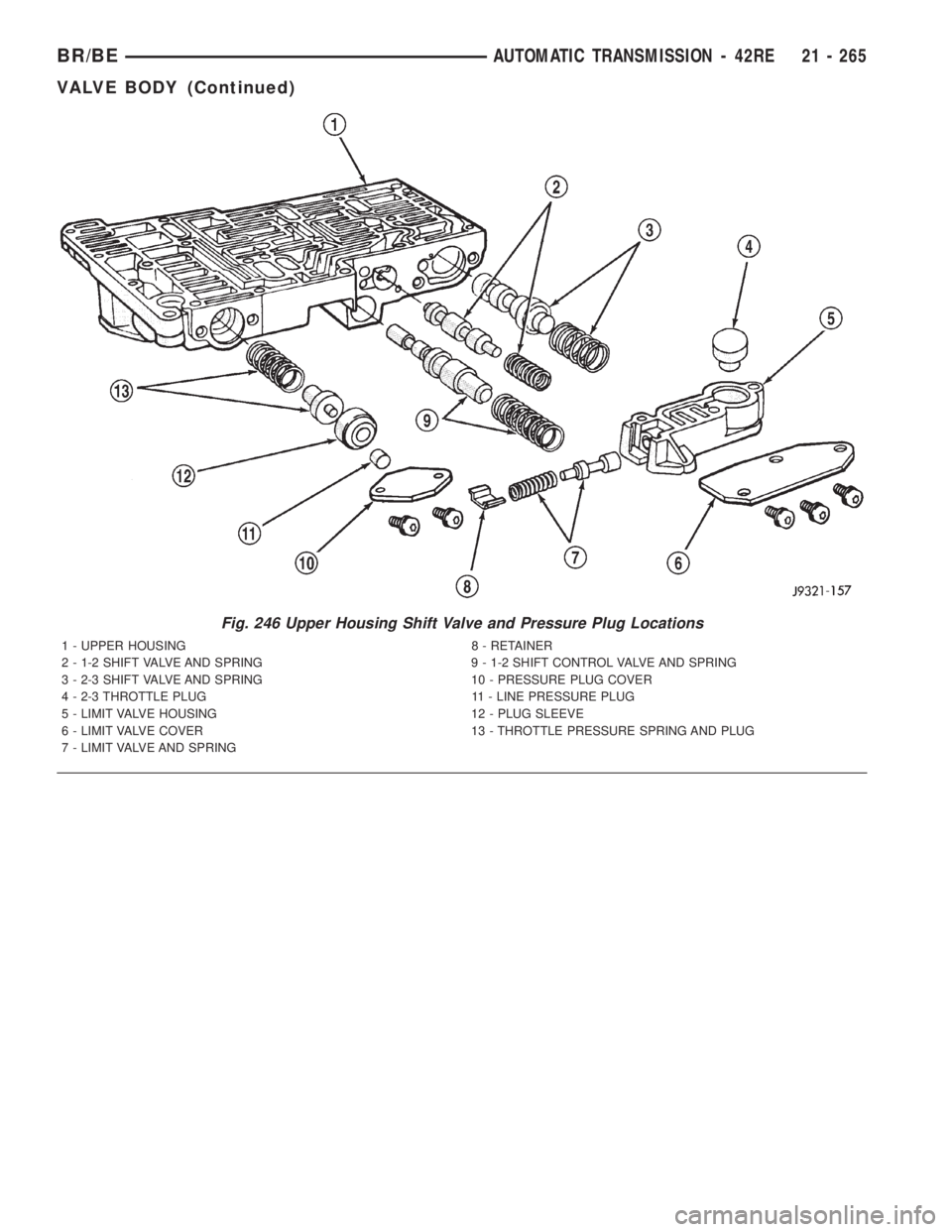
Fig. 246 Upper Housing Shift Valve and Pressure Plug Locations
1 - UPPER HOUSING 8 - RETAINER
2 - 1-2 SHIFT VALVE AND SPRING 9 - 1-2 SHIFT CONTROL VALVE AND SPRING
3 - 2-3 SHIFT VALVE AND SPRING 10 - PRESSURE PLUG COVER
4 - 2-3 THROTTLE PLUG 11 - LINE PRESSURE PLUG
5 - LIMIT VALVE HOUSING 12 - PLUG SLEEVE
6 - LIMIT VALVE COVER 13 - THROTTLE PRESSURE SPRING AND PLUG
7 - LIMIT VALVE AND SPRING
BR/BEAUTOMATIC TRANSMISSION - 42RE 21 - 265
VALVE BODY (Continued)