steering column DODGE RAM 2001 Service User Guide
[x] Cancel search | Manufacturer: DODGE, Model Year: 2001, Model line: RAM, Model: DODGE RAM 2001Pages: 2889, PDF Size: 68.07 MB
Page 446 of 2889
CHIME/BUZZER
TABLE OF CONTENTS
page page
CHIME WARNING SYSTEM
DESCRIPTION............................1
OPERATION.............................1DIAGNOSIS AND TESTING..................2
CHIME WARNING SYSTEM................2
CHIME WARNING SYSTEM
DESCRIPTION
A chime warning system is standard factory-in-
stalled equipment on this model. The chime warning
system uses a single chime tone generator that is
integral to the Central Timer Module (CTM) to pro-
vide an audible indication of various vehicle condi-
tions that may require the attention of the vehicle
operator. The chime warning system includes the fol-
lowing major components, which are described in fur-
ther detail elsewhere in this service manual:
²Central Timer Module- The Central Timer
Module (CTM) is located under the driver side end of
the instrument panel, inboard of the instrument
panel steering column opening. The CTM contains an
integral chime tone generator to provide all of the
proper chime warning system features based upon
the monitored inputs.
²Door Ajar Switch- A door ajar switch is inte-
gral to the driver side front door latch. This switch
provides an input to the chime warning system indi-
cating whether the driver side front door is open or
closed.
²Headlamp Switch- The headlamp switch is
located on the instrument panel outboard of the
steering column. The headlamp switch provides an
input to the chime warning system indicating when
the exterior lamps are turned On or Off.
²Ignition Switch- A key-in ignition switch is
integral to the ignition switch. The key-in ignition
switch provides an input to the chime warning sys-
tem indicating whether a key is present in the igni-
tion lock cylinder.
²Seat Belt Switch- A seat belt switch is inte-
gral to the driver side front seat belt retractor unit.
The seat belt switch provides an input to the chime
warning system indicating whether the driver side
front seat belt is fastened.
Hard wired circuitry connects many of the chime
warning system components to each other through
the electrical system of the vehicle. These hard wired
circuits are integral to several wire harnesses, which
are routed throughout the vehicle and retained bymany different methods. These circuits may be con-
nected to each other, to the vehicle electrical system
and to the chime warning system components
through the use of a combination of soldered splices,
splice block connectors, and many different types of
wire harness terminal connectors and insulators.
Refer to the appropriate wiring information. The wir-
ing information includes wiring diagrams, proper
wire and connector repair procedures, further details
on wire harness routing and retention, as well as
pin-out and location views for the various wire har-
ness connectors, splices and grounds.
The CTM chime warning system circuitry and the
integral chime tone generator cannot be adjusted or
repaired. If the CTM or the chime tone generator are
damaged or faulty, the CTM unit must be replaced.
OPERATION
The chime warning system is designed to provide an
audible output as an indication of various conditions
that may require the attention or awareness of the
vehicle operator. The chime warning system compo-
nents operate on battery current received through a
fused B(+) fuse in the Junction Block (JB) on a non-
switched fused B(+) circuit so that the system may
operate regardless of the ignition switch position.
The chime warning system provides an audible
indication to the vehicle operator under the following
conditions:
²Fasten Seat Belt Warning- The Central
Timer Module (CTM) chime tone generator will gen-
erate repetitive chime tones at a slow rate to
announce that a hard wired input from the seat belt
switch to the Electro-Mechanical Instrument Cluster
(EMIC) indicates that the driver side front seat belt
is not fastened with the ignition switch in the On
position. Unless the driver side front seat belt is fas-
tened, the chimes will continue to sound for a dura-
tion of about seven seconds each time the ignition
switch is turned to the On position or until the driver
side front seat belt is fastened, whichever occurs
first. This chime tone is based upon a hard wired
chime request input to the CTM from the EMIC, but
is not related to the operation of the EMIC ªSeatbeltº
indicator.
BR/BECHIME/BUZZER 8B - 1
Page 448 of 2889
WARNING: ON VEHICLES EQUIPPED WITH AIR-
BAGS, DISABLE THE AIRBAG SYSTEM BEFORE
ATTEMPTING ANY STEERING WHEEL, STEERING
COLUMN, OR INSTRUMENT PANEL COMPONENT
DIAGNOSIS OR SERVICE. DISCONNECT AND ISO-
LATE THE BATTERY NEGATIVE (GROUND) CABLE,
THEN WAIT TWO MINUTES FOR THE AIRBAG SYS-TEM CAPACITOR TO DISCHARGE BEFORE PER-
FORMING FURTHER DIAGNOSIS OR SERVICE. THIS
IS THE ONLY SURE WAY TO DISABLE THE AIRBAG
SYSTEM. FAILURE TO TAKE THE PROPER PRE-
CAUTIONS COULD RESULT IN ACCIDENTAL AIR-
BAG DEPLOYMENT AND POSSIBLE PERSONAL
INJURY.
CHIME WARNING SYSTEM DIAGNOSIS
CONDITION POSSIBLE CAUSES CORRECTION
SEAT BELT WARNING
CHIME WITH SEAT BELT
BUCKLED1. Seat belt switch sense
circuit shorted.1. Disconnect the body wire harness connector
for the seat belt switch and the instrument panel
wire harness connector (Connector C2) for the
EMIC. Check for continuity between the seat belt
switch sense circuit cavity and a good ground.
There should be no continuity. Repair the seat
belt switch sense circuit, if required.
2. Faulty seat belt switch. 2. Check for continuity between the ground circuit
cavity and the seat belt switch sense circuit cavity
of the seat belt switch connector receptacle.
There should be no continuity with the seat belt
buckled. Replace the faulty seat belt, if required.
NO SEAT BELT WARNING
CHIME WITH SEAT BELT
UNBUCKLED, BUT OTHER
CHIME FEATURES OK1. Seat belt switch ground
circuit open.1. Disconnect the body wire harness connector
for the seat belt switch. Check for continuity
between the ground circuit cavity of the connector
for the seat belt switch and a good ground. There
should be continuity. If not OK, repair the open
ground circuit to ground as required.
2. Seat belt switch sense
circuit open.2. With the body wire harness connector for the
seat belt switch and the instrument panel wire
harness connector (Connector C2) for the EMIC
disconnected, there should be continuity between
the seat belt switch sense circuit cavities of the
two connectors. Repair the seat belt switch sense
circuit, if required.
3. Faulty seat belt switch. 3. Check for continuity between the ground circuit
cavity and the seat belt switch sense circuit cavity
of the seat belt switch connector receptacle.
There should be continuity with the seat belt
unbuckled. Replace the faulty seat belt, if
required.
BR/BECHIME/BUZZER 8B - 3
CHIME WARNING SYSTEM (Continued)
Page 452 of 2889
ELECTRONIC CONTROL MODULES
TABLE OF CONTENTS
page page
BODY CONTROL/CENTRAL TIMER MODULE
DESCRIPTION............................1
OPERATION.............................3
DIAGNOSIS AND TESTING..................4
CENTRAL TIMER MODULE................4
REMOVAL...............................5
INSTALLATION............................6
COMMUNICATION
DESCRIPTION............................6
OPERATION.............................7
DIAGNOSIS AND TESTING.................11
CCDDATABUS ........................11
CONTROLLER ANTILOCK BRAKE
DESCRIPTION...........................11
OPERATION.............................11REMOVAL..............................12
INSTALLATION...........................12
DATA LINK CONNECTOR
DESCRIPTION...........................12
OPERATION.............................12
ENGINE CONTROL MODULE
DESCRIPTION...........................13
OPERATION.............................13
REMOVAL..............................14
INSTALLATION...........................14
POWERTRAIN CONTROL MODULE
DESCRIPTION...........................14
OPERATION.............................17
REMOVAL..............................19
INSTALLATION...........................20
BODY CONTROL/CENTRAL
TIMER MODULE
DESCRIPTION
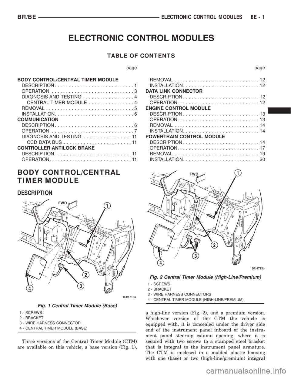
Three versions of the Central Timer Module (CTM)
are available on this vehicle, a base version (Fig. 1),a high-line version (Fig. 2), and a premium version.
Whichever version of the CTM the vehicle is
equipped with, it is concealed under the driver side
end of the instrument panel inboard of the instru-
ment panel steering column opening, where it is
secured with two screws to a stamped steel bracket
that is integral to the instrument panel armature.
The CTM is enclosed in a molded plastic housing
with one (base) or two (high-line/premium) integral
Fig. 1 Central Timer Module (Base)
1 - SCREWS
2 - BRACKET
3 - WIRE HARNESS CONNECTOR
4 - CENTRAL TIMER MODULE (BASE)
Fig. 2 Central Timer Module (High-Line/Premium)
1 - SCREWS
2 - BRACKET
3 - WIRE HARNESS CONNECTORS
4 - CENTRAL TIMER MODULE (HIGH-LINE/PREMIUM)
BR/BEELECTRONIC CONTROL MODULES 8E - 1
Page 454 of 2889
base version of the CTM and the hard wired inputs
or outputs of all CTM versions can be diagnosed
using conventional diagnostic tools and methods;
however, for diagnosis of the high-line or premium
versions of the CTM or the CCD data bus, the use of
a DRBIIItscan tool is required. Refer to the appro-
priate diagnostic information.
OPERATION
The Central Timer Module (CTM) is designed to
control and integrate many of the electronic features
and functions of the vehicle. The base version of the
CTM monitors only hard wired inputs and responds
with the proper hard wired outputs. The microproces-
sor-based high-line/premium version of the CTM
monitors many hard wired switch and sensor inputs
as well as those resources it shares with other elec-
tronic modules in the vehicle through its communica-
tion over the Chrysler Collision Detection (CCD) data
bus network. The internal programming and all of
these inputs allow the high-line/premium CTM
microprocessor to determine the tasks it needs to
perform and their priorities, as well as both the stan-
dard and optional features that it should provide.
The high-line/premium CTM programming then per-
forms those tasks and provides those features
through both CCD data bus communication with
other electronic modules and through hard wired out-
puts to a number of circuits, relays, and actuators.
These outputs allow the high-line/premium CTM the
ability to control numerous accessory systems in the
vehicle.
All versions of the CTM operate on battery current
received through fuses in the Junction Block (JB) on
a non-switched fused B(+) circuit, a fused ignition
switch output (st-run) circuit (base version only), and
a fused ignition switch output (run-acc) circuit (high-
line/premium version only). This arrangement allows
the CTM to provide some features regardless of the
ignition switch position, while other features will
operate only with the ignition switch in the Acces-
sory, On, and/or Start positions. All versions of the
CTM are grounded through their connector and take
out of the instrument panel wire harness. The high-
line/premium CTM has another ground received
through a second connector and take out of the
instrument panel wire harness. The first ground cir-
cuit receives ground through a take out with an eye-
let terminal connector of the instrument panel wire
harness that is secured by a nut to a ground stud
located on the left instrument panel end bracket,
while the second ground circuit (high-line/premium
version only) receives ground through a take out with
an eyelet terminal connector of the instrument panel
wire harness that is secured by a nut to a ground
stud located on the back of the instrument panelarmature above the inboard side of the instrument
panel steering column opening.
The high-line/premium CTM monitors its own
internal circuitry as well as many of its input and
output circuits, and will store a Diagnostic Trouble
Code (DTC) in electronic memory for any failure it
detects. These DTCs can be retrieved and diagnosed
using a DRBIIItscan tool. Refer to the appropriate
diagnostic information.
HARD WIRED INPUTS
The hard wired inputs to the CTM include the fol-
lowing:
²CCD bus± - high-line/premium version only
²CCD bus+ - high-line/premium version only
²Cylinder lock switch mux - high-line premium
version only
²Driver door ajar switch sense
²Fused B(+)
²Fused ignition switch output (run-acc) - high-
line/premium version only
²Fused ignition switch output (st-run) - base ver-
sion only
²Ground (one circuit - base version, two circuits -
high-line/premium version)
²Key-in ignition switch sense
²Passenger door ajar switch sense - high-line/pre-
mium version only
²Power door lock motor B(+) lock - high-line/pre-
mium version only
²Power door lock motor B(+) unlock - high-line/
premium version only
²Radio control mux - high-line/premium version
only
²Tone request signal
²Washer switch sense
²Wiper park switch sense
²Wiper switch mode sense
²Wiper switch mode signal
HARD WIRED OUTPUTS
The hard wired outputs of the CTM include the fol-
lowing:
²CCD bus± - high-line/premium version only
²CCD bus+ - high-line/premium version only
²Courtesy lamp switch output - high-line/pre-
mium version only
²Door lock driver - high-line/premium version
only
²Door unlock driver - high-line/premium version
only
²Headlamp relay control - high-line/premium ver-
sion only
²Heated seat relay control - premium version
only
BR/BEELECTRONIC CONTROL MODULES 8E - 3
BODY CONTROL/CENTRAL TIMER MODULE (Continued)
Page 455 of 2889
²Horn relay control - high-line/premium version
only
²VTSS indicator driver - high-line/premium ver-
sion only
²Wiper motor relay control
MESSAGING
The high-line/premium CTM uses the following
messages received from other electronic modules over
the CCD data bus:
²Airbag Deploy (ACM)
²Charging System Failure (PCM)
²Engine RPM (PCM)
²System Voltage (PCM)
²Vehicle Speed (PCM)
²Voltage Fault (PCM)
The high-line/premium CTM provides the following
messages to other electronic modules over the CCD
data bus:
²Engine Enable (PCM)
²Radio Seek Up (Radio)
²Radio Seek Down (Radio)
²Radio Volume Up (Radio)
²Radio Volume Down (Radio)
²Preset Scan (Radio)
DIAGNOSIS AND TESTING - CENTRAL TIMER
MODULE
The hard wired inputs to and outputs from the
Central Timer Module (CTM) may be diagnosed and
tested using conventional diagnostic tools and meth-
ods. Refer to the appropriate wiring information. The
wiring information includes wiring diagrams, proper
wire and connector repair procedures, further details
on wire harness routing and retention, as well as
pin-out and location views for the various wire har-
ness connectors, splices and grounds.
However, conventional diagnostic methods may not
prove conclusive in the diagnosis of the high-line/pre-
mium CTM. In order to obtain conclusive testing of
the high-line/premium CTM, the Chrysler Collision
Detection (CCD) data bus network and all of the elec-
tronic modules that provide inputs to or receive out-
puts from the CTM must also be checked. The most
reliable, efficient, and accurate means to diagnose
the high-line/premium CTM, the CCD data bus net-
work, and the electronic modules that provide inputs
to or receive outputs from the high-line/premium
CTM requires the use of a DRBIIItscan tool and the
appropriate diagnostic information. The DRBIIIt
scan tool can provide confirmation that the CCD data
bus network is functional, that all of the electronic
modules are sending and receiving the proper mes-
sages over the CCD data bus, and that the CTM is
receiving the proper hard wired inputs and respond-ing with the proper hard wired outputs needed to
perform its many functions.
WARNING: ON VEHICLES EQUIPPED WITH AIR-
BAGS, DISABLE THE AIRBAG SYSTEM BEFORE
ATTEMPTING ANY STEERING WHEEL, STEERING
COLUMN, OR INSTRUMENT PANEL COMPONENT
DIAGNOSIS OR SERVICE. DISCONNECT AND ISO-
LATE THE BATTERY NEGATIVE (GROUND) CABLE,
THEN WAIT TWO MINUTES FOR THE AIRBAG SYS-
TEM CAPACITOR TO DISCHARGE BEFORE PER-
FORMING FURTHER DIAGNOSIS OR SERVICE. THIS
IS THE ONLY SURE WAY TO DISABLE THE AIRBAG
SYSTEM. FAILURE TO TAKE THE PROPER PRE-
CAUTIONS COULD RESULT IN ACCIDENTAL AIR-
BAG DEPLOYMENT AND POSSIBLE PERSONAL
INJURY.
NOTE: The following tests may not prove conclu-
sive in the diagnosis of the high-line or premium
versions of the Central Timer Module (CTM). The
most reliable, efficient, and accurate means to diag-
nose the high-line or premium CTM requires the
use of a DRBIIITscan tool and the appropriate diag-
nostic information.
(1) Check the fused B(+) fuse (Fuse 13 - 10
ampere) in the Junction Block (JB). If OK, go to Step
2. If not OK, repair the shorted circuit or component
as required and replace the faulty fuse.
(2) Check for battery voltage at the fused B(+) fuse
(Fuse 13 - 10 ampere) in the JB. If OK, go to Step 3.
If not OK, repair the open fused B(+) circuit between
the JB and the Power Distribution Center (PDC) as
required.
(3) For a base version CTM, check the fused igni-
tion switch output (st-run) fuse (Fuse 11 - 10 ampere)
in the JB. For a high-line/premium version CTM,
check the fused ignition switch output (run-acc) fuse
(Fuse6-25ampere) in the JB. If OK, go to Step 4. If
not OK, repair the shorted circuit or component as
required and replace the faulty fuse.
(4) Turn the ignition switch to the On position. For
a base version CTM, check for battery voltage at the
fused ignition switch output (st-run) fuse (Fuse 11 -
10 ampere) in the JB. For a high-line/premium ver-
sion CTM, check for battery voltage at the fused igni-
tion switch output (run-acc) fuse (Fuse6-25
ampere) in the JB. If OK, go to Step 5. If not OK,
repair the shorted circuit or component as required
and replace the faulty fuse.
(5) Turn the ignition switch to the Off position.
Disconnect and isolate the battery negative cable.
Remove the CTM from its mounting bracket to access
the CTM wire harness connector(s). Disconnect the
instrument panel wire harness connector(s) for the
8E - 4 ELECTRONIC CONTROL MODULESBR/BE
BODY CONTROL/CENTRAL TIMER MODULE (Continued)
Page 456 of 2889
CTM from the CTM connector receptacle(s). Check
the wire harness connectors and the CTM receptacles
for loose, corroded, or damaged terminals and pins. If
OK, go to Step 6. If not OK, repair as required.
(6) Check for continuity between the ground cir-
cuit cavity of the instrument panel wire harness con-
nector (Connector C1) for the CTM and a good
ground. For the high-line/premium version of the
CTM only, repeat the check between the ground cir-
cuit cavity of the instrument panel wire harness con-
nector (Connector C2) for the CTM and a good
ground. In each case, there should be continuity. If
OK, go to Step 7. If not OK, repair the open ground
circuit(s) to ground as required.
(7) Reconnect the battery negative cable. Check for
battery voltage at the fused B(+) circuit cavity of the
instrument panel wire harness connector (Connector
C1) for the CTM. If OK, go to Step 8. If not OK,
repair the open fused B(+) circuit between the CTM
and the JB as required.
(8) Turn the ignition switch to the On position.
Check for battery voltage at the fused ignition switch
output (st-run) circuit cavity (base version) or fused
ignition switch output (run-acc) circuit cavity (high-
line/premium version) of the instrument panel wire
harness connector (Connector C1) for the CTM. If OK
with a base version CTM, replace the faulty CTM. If
OK with a high-line/premium version CTM, use a
DRBIIItscan tool and the appropriate diagnostic
information to perform further diagnosis of the CTM.
If not OK, repair the open fused ignition switch out-
put circuit between the CTM and the JB.
REMOVAL
WARNING: ON VEHICLES EQUIPPED WITH AIR-
BAGS, DISABLE THE AIRBAG SYSTEM BEFORE
ATTEMPTING ANY STEERING WHEEL, STEERING
COLUMN, OR INSTRUMENT PANEL COMPONENT
DIAGNOSIS OR SERVICE. DISCONNECT AND ISO-
LATE THE BATTERY NEGATIVE (GROUND) CABLE,
THEN WAIT TWO MINUTES FOR THE AIRBAG SYS-
TEM CAPACITOR TO DISCHARGE BEFORE PER-
FORMING FURTHER DIAGNOSIS OR SERVICE. THIS
IS THE ONLY SURE WAY TO DISABLE THE AIRBAG
SYSTEM. FAILURE TO TAKE THE PROPER PRE-
CAUTIONS COULD RESULT IN ACCIDENTAL AIR-
BAG DEPLOYMENT AND POSSIBLE PERSONAL
INJURY.
NOTE: Before replacing a high-line/premium version
Central Timer Module (CTM), use a DRBIIITscan
tool to retrieve the current settings for the CTM pro-
grammable features. Refer to the appropriate diag-
nostic information. These settings should be
duplicated in the replacement high-line/premiumCTM using the DRBIIITscan tool before returning
the vehicle to service.
(1) Disconnect and isolate the battery negative
cable.
(2) Remove the steering column opening cover
from the instrument panel. (Refer to 23 - BODY/IN-
STRUMENT PANEL/STEERING COLUMN OPEN-
ING COVER - REMOVAL).
(3) Remove the two screws that secure the Central
Timer Module (CTM) to the bracket on the inboard
side of the instrument panel steering column opening
(Fig. 3) or (Fig. 4).
(4) Pull the CTM into the instrument panel steer-
ing column opening far enough to access the instru-
ment panel wire harness connector(s).
(5) Disconnect the instrument panel wire harness
connector(s) (one connector for the base version CTM,
two connectors for the high-line/premium version)
from the CTM connector receptacle(s).
(6) Remove the CTM from the instrument panel.
Fig. 3 Central Timer Module (Base) Remove/Install
1 - SCREWS
2 - BRACKET
3 - WIRE HARNESS CONNECTOR
4 - CENTRAL TIMER MODULE (BASE)
BR/BEELECTRONIC CONTROL MODULES 8E - 5
BODY CONTROL/CENTRAL TIMER MODULE (Continued)
Page 457 of 2889
INSTALLATION
WARNING: ON VEHICLES EQUIPPED WITH AIR-
BAGS, DISABLE THE AIRBAG SYSTEM BEFORE
ATTEMPTING ANY STEERING WHEEL, STEERING
COLUMN, OR INSTRUMENT PANEL COMPONENT
DIAGNOSIS OR SERVICE. DISCONNECT AND ISO-
LATE THE BATTERY NEGATIVE (GROUND) CABLE,
THEN WAIT TWO MINUTES FOR THE AIRBAG SYS-
TEM CAPACITOR TO DISCHARGE BEFORE PER-
FORMING FURTHER DIAGNOSIS OR SERVICE. THIS
IS THE ONLY SURE WAY TO DISABLE THE AIRBAG
SYSTEM. FAILURE TO TAKE THE PROPER PRE-
CAUTIONS COULD RESULT IN ACCIDENTAL AIR-
BAG DEPLOYMENT AND POSSIBLE PERSONAL
INJURY.
NOTE: Before replacing a high-line/premium version
Central Timer Module (CTM), use a DRBIIITscan
tool to retrieve the current settings for the CTM pro-
grammable features. Refer to the appropriate diag-
nostic information. These settings should be
duplicated in the replacement high-line/premium
CTM using the DRBIIITscan tool before returning
the vehicle to service.(1) Position the CTM to the inboard side of the
instrument panel steering column opening.
(2) Reconnect the instrument panel wire harness
connector(s) for the CTM (one connector for the base
version CTM, two connectors for the high-line/pre-
mium version) to the CTM connector receptacle(s)
(Fig. 3) or (Fig. 4).
(3) Position the CTM to the bracket on the inboard
side of the instrument panel steering column open-
ing.
(4) Install and tighten the two screws that secure
the CTM to the bracket on the inboard side of instru-
ment panel steering column opening. Tighten the
screws to 1.6 N´m (15 in. lbs.).
(5) Reinstall the steering column opening cover
onto the instrument panel. (Refer to 23 - BODY/IN-
STRUMENT PANEL/STEERING COLUMN OPEN-
ING COVER - INSTALLATION).
(6) Reconnect the battery negative cable.
COMMUNICATION
DESCRIPTION - CCD DATA BUS
The Chrysler Collision Detection (also referred to
as CCD or C2D ) data bus system is a multiplex sys-
tem used for vehicle communications on many
Chrysler Corporation vehicles. Within the context of
the CCD system, the term ªcollisionª refers to the
system's ability to avoid collisions of the electronic
data that enters the data bus from various electronic
control modules at approximately the same time.
Multiplexing is a system that enables the trans-
mission of several messages over a single channel or
circuit. Many Chrysler vehicles use this principle for
communication between the various microprocessor-
based electronic control modules.
Many of the electronic control modules in a vehicle
require information from the same sensing device. In
the past, if information from one sensing device was
required by several controllers, a wire from each con-
troller needed to be connected in parallel to that sen-
sor. In addition, each controller utilizing analog
sensors required an Analog/Digital (A/D) converter in
order to ªreadª these sensor inputs. Multiplexing
reduces wire harness complexity, sensor current
loads and controller hardware because each sensing
device is connected to only one controller, which
reads and distributes the sensor information to the
other controllers over the data bus. Also, because
each controller on the data bus can access the con-
troller sensor inputs to every other controller on the
data bus, more function and feature capabilities are
possible.
Fig. 4 Central Timer Module (High-Line/Premium)
Remove/Install
1 - SCREWS
2 - BRACKET
3 - WIRE HARNESS CONNECTORS
4 - CENTRAL TIMER MODULE (HIGH-LINE/PREMIUM)
8E - 6 ELECTRONIC CONTROL MODULESBR/BE
BODY CONTROL/CENTRAL TIMER MODULE (Continued)
Page 505 of 2889
Starting System Diagnosis
CONDITION POSSIBLE CAUSE CORRECTION
STARTER ENGAGES,
SPINS OUT BEFORE
ENGINE STARTS.1. Starter ring gear faulty. 1. Refer to Starter Motor in Removal and Installation.
Remove starter motor to inspect starter ring gear.
Replace starter ring gear, if required.
2. Starter motor faulty. 2. If all other starting system components and circuits test
OK, replace the starter motor assembly.
STARTER DOES NOT
DISENGAGE.1. Starter motor
improperly installed.1. Refer to Starter Motor in the Removal and Installation
section of this group. Tighten the starter mounting
hardware to the correct tightness specifications.
2. Starter relay faulty. 2. Refer to Starter Relay in the Diagnosis and Testing
section of this group. Replace starter relay, if required.
3. Ignition switch faulty. 3. Refer to Ignition Switch and Key Lock Cylinder.
Replace ignition switch, if required.
4. Starter motor faulty. 4. If all other starting system components and circuits test
OK, replace starter motor.
INSPECTION
For complete starter wiring circuit diagrams, refer
to 8, Wiring Diagrams. Before removing any unit
from starting system for repair or diagnosis, perform
the following inspections:
WARNING: ON VEHICLES EQUIPPED WITH AIR-
BAGS, REFER TO 8, PASSIVE RESTRAINT SYS-
TEMS, BEFORE ATTEMPTING ANY STEERING
WHEEL, STEERING COLUMN, OR INSTRUMENT
PANEL COMPONENT DIAGNOSIS OR SERVICE.
FAILURE TO TAKE THE PROPER PRECAUTIONS
COULD RESULT IN ACCIDENTAL AIRBAG DEPLOY-
MENT AND POSSIBLE PERSONAL INJURY.
²Battery- Visually inspect battery for indica-
tions of physical damage and loose or corroded cable
connections. Determine the state-of-charge and
cranking capacity of battery. Charge or replace bat-
tery, if required. Refer toBatteryin 8, Battery.
Note: If equipped with diesel engine, a dual bat-
tery system is used, and both batteries must be
inspected.
²Ignition Switch- Visually inspect ignition
switch for indications of physical damage and loose
or corroded wire harness connections. Refer toIgni-
tion Switch and Key Lock Cylinder.
²Clutch Pedal Position Switch- If equipped
with manual transmission, visually inspect clutch
pedal position switch for indications of physical dam-
age and loose or corroded wire harness connections.
Refer toClutch Pedal Position Switchin 6,
Clutch.
²Park/Neutral Position Switch- If equipped
with automatic transmission, visually inspect park/
neutral position switch for indications of physical
damage and loose or corroded wire harness connec-tions. Refer toPark/Neutral Position Switchin
21, Transmission.
²Starter Relay- Visually inspect starter relay
for indications of physical damage and loose or cor-
roded wire harness connections.
²Starter Motor- Visually inspect starter motor
for indications of physical damage and loose or cor-
roded wire harness connections.
²Starter Solenoid- Visually inspect starter sole-
noid for indications of physical damage and loose or
corroded wire harness connections.
²Wiring- Visually inspect wire harnesses for
damage. Repair or replace any faulty wiring, as
required. Refer to 8, Wiring Diagrams.
TESTING
COLD CRANKING TEST
For complete starter wiring circuit diagrams, refer
to 8, Wiring Diagrams. The battery must be fully-
charged and load-tested before proceeding. Refer to
Batteryin 8, Battery.
(1) Connect volt-ampere tester to battery terminals
(Fig. 1). See instructions provided by manufacturer of
volt-ampere tester being used.Note: If equipped
with dual battery system (diesel), tester should
be connected to driver side battery only. Also,
tester current reading must be taken from bat-
tery positive cable lead that connects to starter
motor.
(2) Fully engage parking brake.
(3) If equipped with manual transmission, place
gearshift selector lever in Neutral position and block
clutch pedal in fully depressed position. If equipped
with automatic transmission, place gearshift selector
lever in Park position.
8F - 34 STARTINGBR/BE
STARTING (Continued)
Page 517 of 2889
OPERATION - HEATED MIRROR SYSTEM
The solid state electronic control logic and timer
circuitry for the heated mirror system receives bat-
tery current from a fuse in the Junction Block (JB)
only when the ignition switch is in the On or Start
positions. After the heated mirror system is turned
On, the electronic control logic and timer circuitry
will automatically turn the system off after a pro-
grammed time interval of about fifteen minutes.
After the initial time interval has expired, if the
heated mirror switch is depressed and released a sec-
ond time during the same ignition cycle, the elec-
tronic control logic and timer circuitry will
automatically turn the heated mirror system off after
a programmed time interval of about five minutes.
The heated mirror system will be shut off automati-
cally if the ignition switch is turned to the Off or
Accessory positions. After the heated mirror system
is turned On, it can also be turned off manually by
depressing and releasing the heated mirror switch a
second time.
When the heated mirror system is turned On, the
heated mirror system control logic and timer cir-
cuitry energizes the heated mirror system indicator
lamp and the heated mirror relay. When energized,
the heated mirror relay supplies fused ignition
switch output (run/start) current from a fuse in the
JB to the outside mirror heating grids located behind
the mirror glass of each of the outside rear view mir-
rors. When energized, each of the outside mirror
heating grids produces enough heat to warm the
glass of the outside rear view mirrors.
DIAGNOSIS AND TESTING - HEATED MIRROR
SYSTEM
If only one of the outside mirror heating grids is
inoperative, perform continuity checks on the circuits
and heater grid for that mirror only. If both outside
mirror heating grids are inoperative, proceed with
the heated mirror system diagnosis as follows. (Refer
to Appropriate Wiring Information).
WARNING: ON VEHICLES EQUIPPED WITH AIR-
BAGS, DISABLE THE AIRBAG SYSTEM BEFORE
ATTEMPTING ANY STEERING WHEEL, STEERING
COLUMN, OR INSTRUMENT PANEL COMPONENT
DIAGNOSIS OR SERVICE. DISCONNECT AND ISO-
LATE THE BATTERY NEGATIVE (GROUND) CABLE,
THEN WAIT TWO MINUTES FOR THE AIRBAG SYS-
TEM CAPACITOR TO DISCHARGE BEFORE PER-
FORMING FURTHER DIAGNOSIS OR SERVICE. THIS
IS THE ONLY SURE WAY TO DISABLE THE AIRBAG
SYSTEM. FAILURE TO TAKE THE PROPER PRE-
CAUTIONS COULD RESULT IN ACCIDENTAL AIR-
BAG DEPLOYMENT AND POSSIBLE PERSONAL
INJURY.The operation of the heated mirror system can be
confirmed in one of the following manners:
²Turn the ignition switch to the On position.
While monitoring the instrument panel voltmeter,
momentarily depress and release the heated mirror
switch. When the heated mirror system is turned On,
a distinct voltmeter needle deflection should be
noted.
²Turn the ignition switch to the On position.
Momentarily depress and release the heated mirror
switch to turn the heated mirror system On. The
heated mirror operation can be checked by feeling
the outside rear view mirror glass. A distinct differ-
ence in temperature between the unheated and
heated mirror glass can be detected within three to
four minutes of system operation.
The above checks will confirm system operation.
Illumination of the heated mirror system indicator
lamp means that there is electrical current available
at the heated mirror relay, but does not confirm that
the electrical current is reaching the outside mirror
heating grids.
If the heated mirror system does not operate, the
problem should be isolated in the following manner:
(1) Confirm that the ignition switch is in the On
position.
(2) Check the fuses in the Power Distribution Cen-
ter (PDC) and in the Junction Block (JB). The fuses
must be tight in their receptacles and all electrical
connections must be secure.
When the above steps have been completed and
both outside mirror heating grids are still inopera-
tive, one or more of the following is faulty:
²Heated mirror switch, electronic control logic
and timer circuitry, and heated mirror relay.
²Heated mirror wire harness circuits or connec-
tors.
²Outside mirror heating grid (both mirror grids
would have to be faulty).
If turning On the heated mirror system produces a
severe voltmeter deflection or fuse failures, check for
a shorted circuit between the output of the heated
mirror relay and the outside mirror heating grids.
8G - 2 HEATED MIRRORSBR/BE
HEATED MIRRORS (Continued)
Page 518 of 2889
MIRROR SWITCH
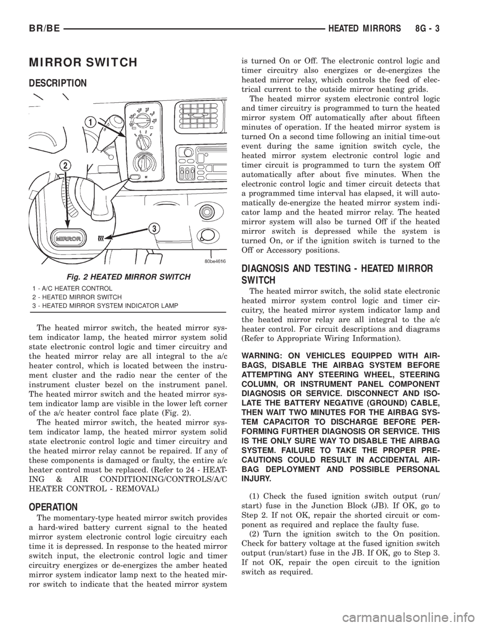
DESCRIPTION
The heated mirror switch, the heated mirror sys-
tem indicator lamp, the heated mirror system solid
state electronic control logic and timer circuitry and
the heated mirror relay are all integral to the a/c
heater control, which is located between the instru-
ment cluster and the radio near the center of the
instrument cluster bezel on the instrument panel.
The heated mirror switch and the heated mirror sys-
tem indicator lamp are visible in the lower left corner
of the a/c heater control face plate (Fig. 2).
The heated mirror switch, the heated mirror sys-
tem indicator lamp, the heated mirror system solid
state electronic control logic and timer circuitry and
the heated mirror relay cannot be repaired. If any of
these components is damaged or faulty, the entire a/c
heater control must be replaced. (Refer to 24 - HEAT-
ING & AIR CONDITIONING/CONTROLS/A/C
HEATER CONTROL - REMOVAL)
OPERATION
The momentary-type heated mirror switch provides
a hard-wired battery current signal to the heated
mirror system electronic control logic circuitry each
time it is depressed. In response to the heated mirror
switch input, the electronic control logic and timer
circuitry energizes or de-energizes the amber heated
mirror system indicator lamp next to the heated mir-
ror switch to indicate that the heated mirror systemis turned On or Off. The electronic control logic and
timer circuitry also energizes or de-energizes the
heated mirror relay, which controls the feed of elec-
trical current to the outside mirror heating grids.
The heated mirror system electronic control logic
and timer circuitry is programmed to turn the heated
mirror system Off automatically after about fifteen
minutes of operation. If the heated mirror system is
turned On a second time following an initial time-out
event during the same ignition switch cycle, the
heated mirror system electronic control logic and
timer circuit is programmed to turn the system Off
automatically after about five minutes. When the
electronic control logic and timer circuit detects that
a programmed time interval has elapsed, it will auto-
matically de-energize the heated mirror system indi-
cator lamp and the heated mirror relay. The heated
mirror system will also be turned Off if the heated
mirror switch is depressed while the system is
turned On, or if the ignition switch is turned to the
Off or Accessory positions.
DIAGNOSIS AND TESTING - HEATED MIRROR
SWITCH
The heated mirror switch, the solid state electronic
heated mirror system control logic and timer cir-
cuitry, the heated mirror system indicator lamp and
the heated mirror relay are all integral to the a/c
heater control. For circuit descriptions and diagrams
(Refer to Appropriate Wiring Information).
WARNING: ON VEHICLES EQUIPPED WITH AIR-
BAGS, DISABLE THE AIRBAG SYSTEM BEFORE
ATTEMPTING ANY STEERING WHEEL, STEERING
COLUMN, OR INSTRUMENT PANEL COMPONENT
DIAGNOSIS OR SERVICE. DISCONNECT AND ISO-
LATE THE BATTERY NEGATIVE (GROUND) CABLE,
THEN WAIT TWO MINUTES FOR THE AIRBAG SYS-
TEM CAPACITOR TO DISCHARGE BEFORE PER-
FORMING FURTHER DIAGNOSIS OR SERVICE. THIS
IS THE ONLY SURE WAY TO DISABLE THE AIRBAG
SYSTEM. FAILURE TO TAKE THE PROPER PRE-
CAUTIONS COULD RESULT IN ACCIDENTAL AIR-
BAG DEPLOYMENT AND POSSIBLE PERSONAL
INJURY.
(1) Check the fused ignition switch output (run/
start) fuse in the Junction Block (JB). If OK, go to
Step 2. If not OK, repair the shorted circuit or com-
ponent as required and replace the faulty fuse.
(2) Turn the ignition switch to the On position.
Check for battery voltage at the fused ignition switch
output (run/start) fuse in the JB. If OK, go to Step 3.
If not OK, repair the open circuit to the ignition
switch as required.
Fig. 2 HEATED MIRROR SWITCH
1 - A/C HEATER CONTROL
2 - HEATED MIRROR SWITCH
3 - HEATED MIRROR SYSTEM INDICATOR LAMP
BR/BEHEATED MIRRORS 8G - 3