remote start DODGE RAM 2001 Service Repair Manual
[x] Cancel search | Manufacturer: DODGE, Model Year: 2001, Model line: RAM, Model: DODGE RAM 2001Pages: 2889, PDF Size: 68.07 MB
Page 686 of 2889
STANDARD PROCEDURE - CLOCKSPRING
CENTERING
The clockspring is designed to wind and unwind
when the steering wheel is rotated, but is only
designed to rotate the same number of turns (about
five complete rotations) as the steering wheel can be
turned from stop to stop. Centering the clockspring
indexes the clockspring tape to other steering compo-
nents so that it can operate within its designed
travel limits. The rotor of a centered clockspring can
be rotated two and one-half turns in either direction
from the centered position, without damaging the
clockspring tape.
However, if the clockspring is removed for service
or if the steering column is disconnected from the
steering gear, the clockspring tape can change posi-
tion relative to the other steering components. The
clockspring must then be re-centered following com-
pletion of such service or the clockspring tape may be
damaged. Service replacement clocksprings are
shipped pre-centered and with the auto-locking tabs
engaged (raised). These auto-locking tabs should not
be disengaged until the clockspring has been
installed on the steering column. If the auto-locking
tabs are disengaged before the clockspring is
installed on a steering column, the clockspring cen-
tering procedure must be performed.
WARNING: DISABLE THE AIRBAG SYSTEM
BEFORE ATTEMPTING ANY STEERING WHEEL,
STEERING COLUMN, OR INSTRUMENT PANEL
COMPONENT DIAGNOSIS OR SERVICE. DISCON-
NECT AND ISOLATE THE BATTERY NEGATIVE
(GROUND) CABLE, THEN WAIT TWO MINUTES FOR
THE AIRBAG SYSTEM CAPACITOR TO DISCHARGE
BEFORE PERFORMING FURTHER DIAGNOSIS OR
SERVICE. THIS IS THE ONLY SURE WAY TO DIS-
ABLE THE AIRBAG SYSTEM. FAILURE TO TAKE
THE PROPER PRECAUTIONS COULD RESULT IN
ACCIDENTAL AIRBAG DEPLOYMENT AND POSSI-
BLE PERSONAL INJURY.
NOTE: Before starting this procedure, be certain to
turn the steering wheel until the front wheels are in
the straight-ahead position.
(1) Place the front wheels in the straight-ahead
position.
(2) Remove the clockspring from the steering col-
umn. (Refer to 8 - ELECTRICAL/RESTRAINTS/
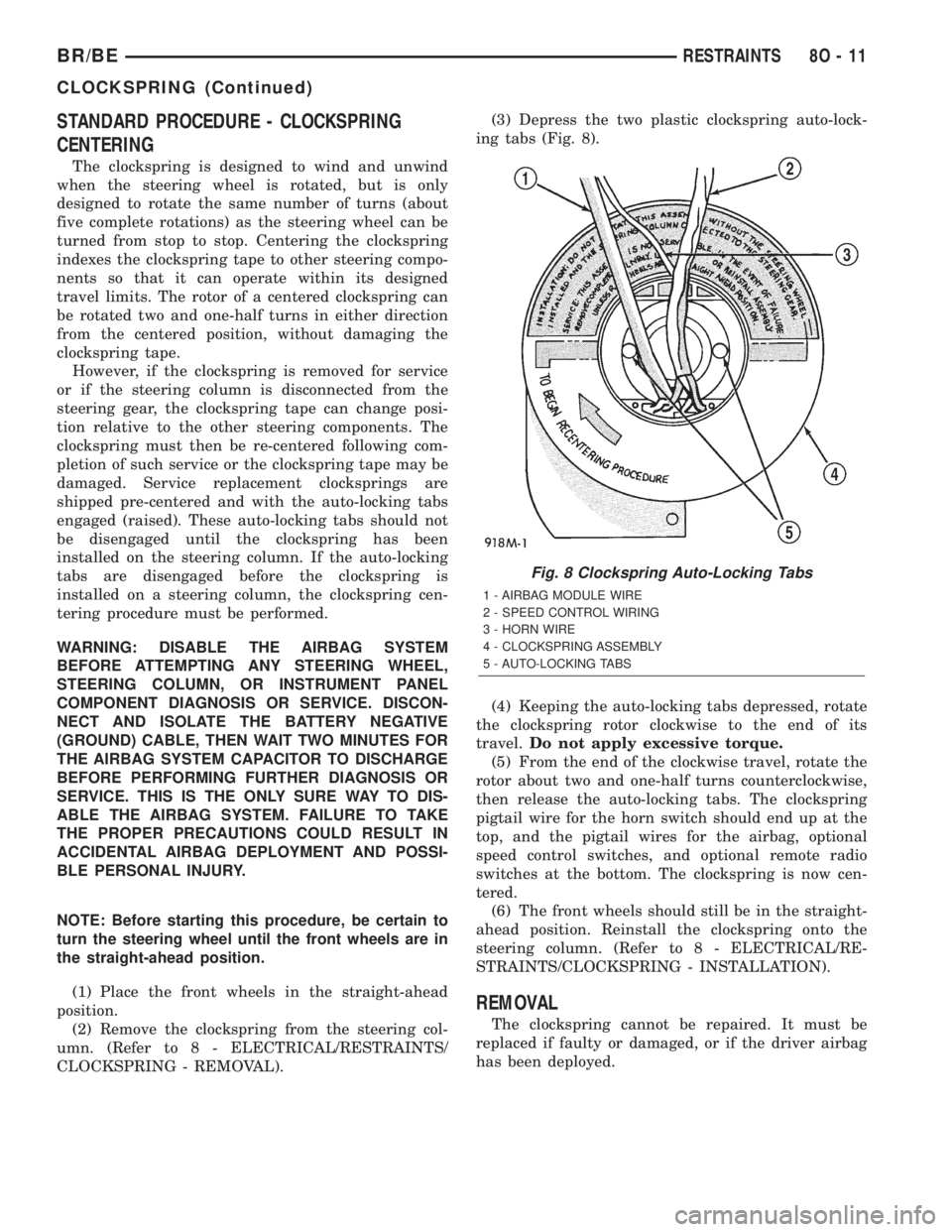
CLOCKSPRING - REMOVAL).(3) Depress the two plastic clockspring auto-lock-
ing tabs (Fig. 8).
(4) Keeping the auto-locking tabs depressed, rotate
the clockspring rotor clockwise to the end of its
travel.Do not apply excessive torque.
(5) From the end of the clockwise travel, rotate the
rotor about two and one-half turns counterclockwise,
then release the auto-locking tabs. The clockspring
pigtail wire for the horn switch should end up at the
top, and the pigtail wires for the airbag, optional
speed control switches, and optional remote radio
switches at the bottom. The clockspring is now cen-
tered.
(6) The front wheels should still be in the straight-
ahead position. Reinstall the clockspring onto the
steering column. (Refer to 8 - ELECTRICAL/RE-
STRAINTS/CLOCKSPRING - INSTALLATION).
REMOVAL
The clockspring cannot be repaired. It must be
replaced if faulty or damaged, or if the driver airbag
has been deployed.
Fig. 8 Clockspring Auto-Locking Tabs
1 - AIRBAG MODULE WIRE
2 - SPEED CONTROL WIRING
3 - HORN WIRE
4 - CLOCKSPRING ASSEMBLY
5 - AUTO-LOCKING TABS
BR/BERESTRAINTS 8O - 11
CLOCKSPRING (Continued)
Page 687 of 2889
WARNING: DISABLE THE AIRBAG SYSTEM
BEFORE ATTEMPTING ANY STEERING WHEEL,
STEERING COLUMN, OR INSTRUMENT PANEL
COMPONENT DIAGNOSIS OR SERVICE. DISCON-
NECT AND ISOLATE THE BATTERY NEGATIVE
(GROUND) CABLE, THEN WAIT TWO MINUTES FOR
THE AIRBAG SYSTEM CAPACITOR TO DISCHARGE
BEFORE PERFORMING FURTHER DIAGNOSIS OR
SERVICE. THIS IS THE ONLY SURE WAY TO DIS-
ABLE THE AIRBAG SYSTEM. FAILURE TO TAKE
THE PROPER PRECAUTIONS COULD RESULT IN
ACCIDENTAL AIRBAG DEPLOYMENT AND POSSI-
BLE PERSONAL INJURY.
NOTE: Before starting this procedure, be certain to
turn the steering wheel until the front wheels are in
the straight-ahead position.
(1) Place the front wheels in the straight-ahead
position.
(2) Remove the driver airbag from the steering
wheel. (Refer to 8 - ELECTRICAL/RESTRAINTS/
DRIVER AIRBAG - REMOVAL).
(3) If the vehicle is so equipped, disconnect the
clockspring pigtail wire connectors from the speed
control switches and the remote radio switches
located within the hub cavity of the steering wheel.
(4) Remove the nut that secures the steering wheel
armature to the steering column upper shaft, which
is located within the hub cavity of the steering wheel.
(5) Pull the steering wheel off of the steering col-
umn upper shaft spline using a steering wheel puller
(Special Tool C-3428-B).
(6) Remove the steering column opening cover
from the instrument panel. (Refer to 23 - BODY/IN-
STRUMENT PANEL/STEERING COLUMN OPEN-
ING COVER - REMOVAL).
(7) If the vehicle is so equipped, unscrew the lever
from the tilt steering column adjuster mechanism
located on the left side of the column just below the
multi-function switch control stalk. Turn the lever
counterclockwise to unscrew it from the adjuster.
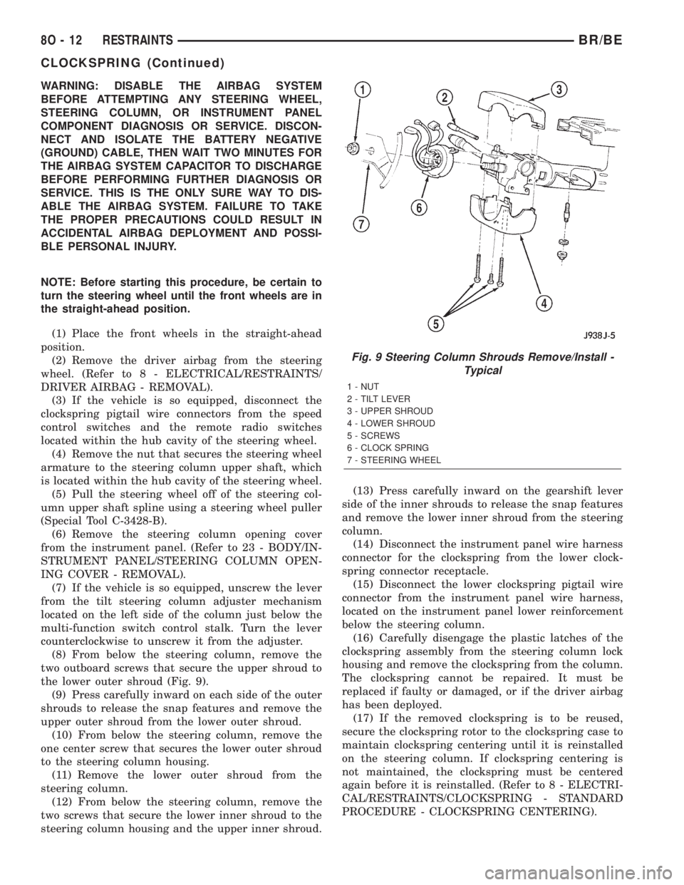
(8) From below the steering column, remove the
two outboard screws that secure the upper shroud to
the lower outer shroud (Fig. 9).
(9) Press carefully inward on each side of the outer
shrouds to release the snap features and remove the
upper outer shroud from the lower outer shroud.
(10) From below the steering column, remove the
one center screw that secures the lower outer shroud
to the steering column housing.
(11) Remove the lower outer shroud from the
steering column.
(12) From below the steering column, remove the
two screws that secure the lower inner shroud to the
steering column housing and the upper inner shroud.(13) Press carefully inward on the gearshift lever
side of the inner shrouds to release the snap features
and remove the lower inner shroud from the steering
column.
(14) Disconnect the instrument panel wire harness
connector for the clockspring from the lower clock-
spring connector receptacle.
(15) Disconnect the lower clockspring pigtail wire
connector from the instrument panel wire harness,
located on the instrument panel lower reinforcement
below the steering column.
(16) Carefully disengage the plastic latches of the
clockspring assembly from the steering column lock
housing and remove the clockspring from the column.
The clockspring cannot be repaired. It must be
replaced if faulty or damaged, or if the driver airbag
has been deployed.
(17) If the removed clockspring is to be reused,
secure the clockspring rotor to the clockspring case to
maintain clockspring centering until it is reinstalled
on the steering column. If clockspring centering is
not maintained, the clockspring must be centered
again before it is reinstalled. (Refer to 8 - ELECTRI-
CAL/RESTRAINTS/CLOCKSPRING - STANDARD
PROCEDURE - CLOCKSPRING CENTERING).
Fig. 9 Steering Column Shrouds Remove/Install -
Typical
1 - NUT
2 - TILT LEVER
3 - UPPER SHROUD
4 - LOWER SHROUD
5 - SCREWS
6 - CLOCK SPRING
7 - STEERING WHEEL
8O - 12 RESTRAINTSBR/BE
CLOCKSPRING (Continued)
Page 688 of 2889
INSTALLATION
The clockspring cannot be repaired. It must be
replaced if faulty or damaged, or if the driver airbag
has been deployed.
If the clockspring is not properly centered in rela-
tion to the steering wheel, steering shaft and steer-
ing gear, it may be damaged. (Refer to 8 -
ELECTRICAL/RESTRAINTS/CLOCKSPRING -
STANDARD PROCEDURE - CLOCKSPRING CEN-
TERING). Service replacement clocksprings are
shipped pre-centered and with a piece of tape cover-
ing the engaged clockspring auto-locking tabs. This
tape should not be removed until the clockspring has
been installed on the steering column. If the tape is
removed before the clockspring is installed on a
steering column, the clockspring centering procedure
must be performed.
WARNING: DISABLE THE AIRBAG SYSTEM
BEFORE ATTEMPTING ANY STEERING WHEEL,
STEERING COLUMN, OR INSTRUMENT PANEL
COMPONENT DIAGNOSIS OR SERVICE. DISCON-
NECT AND ISOLATE THE BATTERY NEGATIVE
(GROUND) CABLE, THEN WAIT TWO MINUTES FOR
THE AIRBAG SYSTEM CAPACITOR TO DISCHARGE
BEFORE PERFORMING FURTHER DIAGNOSIS OR
SERVICE. THIS IS THE ONLY SURE WAY TO DIS-
ABLE THE AIRBAG SYSTEM. FAILURE TO TAKE
THE PROPER PRECAUTIONS COULD RESULT IN
ACCIDENTAL AIRBAG DEPLOYMENT AND POSSI-
BLE PERSONAL INJURY.
NOTE: Before starting this procedure, be certain
that the front wheels are still in the straight-ahead
position.
(1) Carefully slide the centered clockspring down
over the steering column upper shaft until the clock-
spring latches engage the steering column lock hous-
ing (Fig. 9).
(2) Reconnect the lower clockspring pigtail wire
connector to the instrument panel wire harness con-
nector located near the instrument panel lower rein-
forcement, below the steering column. Be certain that
the pigtail wire locator clips are properly seated on
the outside of the wiring trough and that the connec-
tor latches are fully engaged.
(3) Reconnect the instrument panel wire harness
connector for the clockspring to the lower clockspring
connector receptacle.
(4) Position the lower inner shroud onto the steer-
ing column. Be certain to insert the gearshift lever
hider strip into the channel located on the inside sur-
face of the shroud.
(5) Align the locking tabs on the gearshift lever
side of the upper inner shroud with the receptacleson the lower inner shroud and apply hand pressure
to snap them together.
(6) From below the steering column, install and
tighten the two screws that secure the lower inner
shroud to the steering column housing and the upper
inner shroud. Tighten the screws to 2 N´m (18 in.
lbs.).
(7) Position the lower outer shroud onto the steer-
ing column. Be certain that the lower clockspring
pigtail wire is routed inside the shrouds.
(8) From below the steering column, install and
tighten the one center screw that secures the lower
outer shroud to the steering column housing. Tighten
the screw to 2 N´m (18 in. lbs.).
(9) Align the locking tabs on the upper outer
shroud with the receptacles on the lower outer
shroud and apply hand pressure to snap them
together.
(10) From below the steering column, install and
tighten the two outboard screws that secure the
lower outer shroud to the upper outer shroud.
Tighten the screws to 2 N´m (18 in. lbs.).
(11) If the vehicle is so equipped, reinstall the
lever into the tilt steering column adjuster on the left
side of the column. Turn the lever clockwise to screw
it into the adjuster.
(12) Reinstall the steering column opening cover
onto the instrument panel. (Refer to 23 - BODY/IN-
STRUMENT PANEL/STEERING COLUMN OPEN-
ING COVER - INSTALLATION).
(13) Reinstall the steering wheel onto the steering
column upper shaft. Be certain to index the flats on
the hub of the steering wheel with the formations on
the inside of the clockspring hub. Pull the upper
clockspring pigtail wires through the upper and
lower holes between the steering wheel back trim
cover and the steering wheel armature.
(14) Install and tighten the steering wheel mount-
ing nut. Tighten the nut to 61 N´m (45 ft. lbs.). Be
certain not to pinch the pigtail wires between the
steering wheel and the nut.
(15) If the vehicle is so equipped, reconnect the
upper clockspring pigtail wire connectors to the
speed control switches and/or the remote radio
switches. Be certain that the upper clockspring pig-
tail wires are routed between the steering wheel back
trim cover and the steering wheel armature.
(16) Reinstall the driver airbag onto the steering
wheel. (Refer to 8 - ELECTRICAL/RESTRAINTS/
DRIVER AIRBAG - INSTALLATION).
BR/BERESTRAINTS 8O - 13
CLOCKSPRING (Continued)
Page 721 of 2889
tem of the vehicle. These hard wired circuits are
integral to several wire harnesses, which are routed
throughout the vehicle and retained by many differ-
ent methods. These circuits may be connected to each
other, to the vehicle electrical system and to the
VTSS components through the use of a combination
of soldered splices, splice block connectors, and many
different types of wire harness terminal connectors
and insulators. Refer to the appropriate wiring infor-
mation. The wiring information includes wiring dia-
grams, proper wire and connector repair procedures,
further details on wire harness routing and reten-
tion, as well as pin-out and location views for the
various wire harness connectors, splices and grounds.
OPERATION
A Central Timer Module (CTM) is used on this
model to control and integrate many of the electronic
functions and features included in the Vehicle Theft
Security System (VTSS). In the VTSS, the CTM
receives inputs indicating the status of the door ajar
switches, the door cylinder lock switch, and the igni-
tion switch. The programming in the CTM allows it
to process the information from all of these inputs
and send control outputs to energize or de-energize
the horn relay, the headlamp relay, and the VTSS
indicator. The control of these inputs and outputs are
what constitute all of the features of the VTSS. Fol-
lowing is information on the operation of each of the
VTSS features. Refer to the owner's manual in the
vehicle glove box for more information on the fea-
tures, use and operation of the VTSS.
ENABLING
The high-line or premium version of the CTM must
have the VTSS function electronically enabled in
order for the VTSS to perform as designed. The logic
in the CTM keeps its VTSS function dormant until it
is enabled using a DRBIIIž scan tool. The VTSS
function of the high-line or premium CTM is enabled
on vehicles equipped with the VTSS option at the
factory, but a service replacement CTM must be
VTSS-enabled by the dealer using a DRBIIIž scan
tool. Refer to the appropriate diagnostic information.
The VTSS engine no-run feature is disabled when
it is shipped from the factory. This is done by pro-
gramming within the Powertrain Control Module
(PCM). The logic in the PCM prevents the VTSS
engine no-run feature from arming until the engine
start counter within the PCM sees twenty engine
starts. The VTSS no-run feature must be enabled by
the dealer when the vehicle is received from the
assembly plant. Once the VTSS engine no-run fea-
ture has been enabled, it cannot be disabled unless
the PCM is replaced with a new unit. The sameVTSS engine no-run feature enable logic will apply
anytime the PCM is replaced with a new unit.
ARMING
Passive arming of the VTSS occurs when the vehi-
cle is exited with the key removed from the ignition
switch, the headlamps are turned off, and the doors
are locked while they are open using the power lock
switch, or locked after they are closed by turning
either front door lock cylinder to the lock position
using the key. The power lock switch will not func-
tion if the key is in the ignition switch or the head-
lamps are turned on with the driver side front door
open. The VTSS will not arm if the doors are locked
using the mechanical lock button. Active arming of
the VTSS occurs when the ªLockº button on the
Remote Keyless Entry (RKE) transmitter is
depressed to lock the vehicle. For active arming to
occur, the doors must be closed and the ignition
switch must be in the Off position when the RKE
transmitter ªLockº button is depressed. However,
once the VTSS arming process has been completed,
the ignition switch can be turned to the Accessory
position without triggering the alarm.
Once the VTSS begins passive or active arming,
the security indicator lamp in the overhead console
will flash rapidly for about fifteen seconds. This indi-
cates that the VTSS arming is in progress. Turning a
key in the ignition switch, opening a door, or unlock-
ing a door by any means during the fifteen second
arming process will cause the VTSS indicator to stop
flashing and the arming process to abort. Once the
fifteen second arming function is successfully com-
pleted, the indicator will flash at a slower rate, indi-
cating that the VTSS is armed.
DISARMING
Passive disarming of the VTSS occurs when the
vehicle is unlocked using the key to unlock either
front door. Active disarming of the VTSS occurs when
the vehicle is unlocked by depressing the ªUnlockº
button of the RKE transmitter. Once the alarm has
been activated (horn pulsing, headlamps flashing,
and the engine no-run feature), either disarming
method will also deactivate the alarm. Depressing
the ªPanicº button on the RKE transmitter willnot
disarm the VTSS.
POWER-UP MODE
When the armed VTSS senses that the battery has
been disconnected and reconnected, it enters its pow-
er-up mode. In the power-up mode the alarm system
remains armed following a battery failure or discon-
nect. If the VTSS was armed prior to a battery dis-
connect or failure, the technician or vehicle operator
will have to actively or passively disarm the alarm
system after the battery is reconnected. The pow-
8Q - 2 VEHICLE THEFT SECURITYBR/BE
VEHICLE THEFT SECURITY (Continued)
Page 808 of 2889
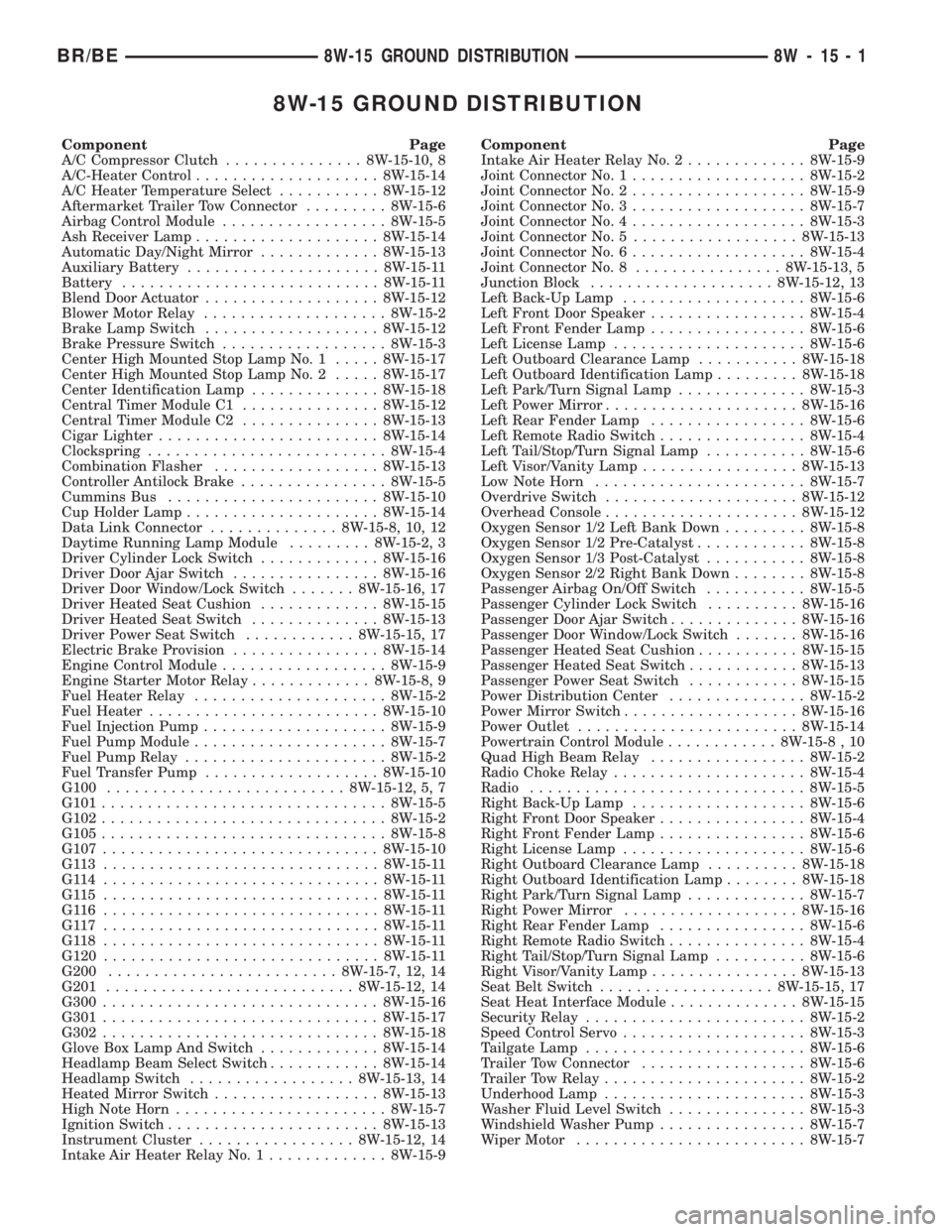
8W-15 GROUND DISTRIBUTION
Component Page
A/C Compressor Clutch............... 8W-15-10, 8
A/C-Heater Control.................... 8W-15-14
A/C Heater Temperature Select........... 8W-15-12
Aftermarket Trailer Tow Connector......... 8W-15-6
Airbag Control Module.................. 8W-15-5
Ash Receiver Lamp.................... 8W-15-14
Automatic Day/Night Mirror............. 8W-15-13
Auxiliary Battery..................... 8W-15-11
Battery............................ 8W-15-11
Blend Door Actuator................... 8W-15-12
Blower Motor Relay.................... 8W-15-2
Brake Lamp Switch................... 8W-15-12
Brake Pressure Switch.................. 8W-15-3
Center High Mounted Stop Lamp No. 1..... 8W-15-17
Center High Mounted Stop Lamp No. 2..... 8W-15-17
Center Identification Lamp.............. 8W-15-18
Central Timer Module C1............... 8W-15-12
Central Timer Module C2............... 8W-15-13
Cigar Lighter........................ 8W-15-14
Clockspring.......................... 8W-15-4
Combination Flasher.................. 8W-15-13
Controller Antilock Brake................ 8W-15-5
Cummins Bus....................... 8W-15-10
Cup Holder Lamp..................... 8W-15-14
Data Link Connector.............. 8W-15-8, 10, 12
Daytime Running Lamp Module......... 8W-15-2, 3
Driver Cylinder Lock Switch............. 8W-15-16
Driver Door Ajar Switch................ 8W-15-16
Driver Door Window/Lock Switch....... 8W-15-16, 17
Driver Heated Seat Cushion............. 8W-15-15
Driver Heated Seat Switch.............. 8W-15-13
Driver Power Seat Switch............ 8W-15-15, 17
Electric Brake Provision................ 8W-15-14
Engine Control Module.................. 8W-15-9
Engine Starter Motor Relay............. 8W-15-8, 9
Fuel Heater Relay..................... 8W-15-2
Fuel Heater......................... 8W-15-10
Fuel Injection Pump.................... 8W-15-9
Fuel Pump Module..................... 8W-15-7
Fuel Pump Relay...................... 8W-15-2
Fuel Transfer Pump................... 8W-15-10
G100.......................... 8W-15-12, 5, 7
G101............................... 8W-15-5
G102............................... 8W-15-2
G105............................... 8W-15-8
G107.............................. 8W-15-10
G113 .............................. 8W-15-11
G114 .............................. 8W-15-11
G115 .............................. 8W-15-11
G116 .............................. 8W-15-11
G117 .............................. 8W-15-11
G118 .............................. 8W-15-11
G120.............................. 8W-15-11
G200......................... 8W-15-7, 12, 14
G201........................... 8W-15-12, 14
G300.............................. 8W-15-16
G301.............................. 8W-15-17
G302.............................. 8W-15-18
Glove Box Lamp And Switch............. 8W-15-14
Headlamp Beam Select Switch............ 8W-15-14
Headlamp Switch.................. 8W-15-13, 14
Heated Mirror Switch.................. 8W-15-13
High Note Horn....................... 8W-15-7
Ignition Switch....................... 8W-15-13
Instrument Cluster................. 8W-15-12, 14
Intake Air Heater Relay No. 1............. 8W-15-9Component Page
Intake Air Heater Relay No. 2............. 8W-15-9
Joint Connector No. 1................... 8W-15-2
Joint Connector No. 2................... 8W-15-9
Joint Connector No. 3................... 8W-15-7
Joint Connector No. 4................... 8W-15-3
Joint Connector No. 5.................. 8W-15-13
Joint Connector No. 6................... 8W-15-4
Joint Connector No. 8................ 8W-15-13, 5
Junction Block.................... 8W-15-12, 13
Left Back-Up Lamp.................... 8W-15-6
Left Front Door Speaker................. 8W-15-4
Left Front Fender Lamp................. 8W-15-6
Left License Lamp..................... 8W-15-6
Left Outboard Clearance Lamp........... 8W-15-18
Left Outboard Identification Lamp......... 8W-15-18
Left Park/Turn Signal Lamp.............. 8W-15-3
Left Power Mirror..................... 8W-15-16
Left Rear Fender Lamp................. 8W-15-6
Left Remote Radio Switch................ 8W-15-4
Left Tail/Stop/Turn Signal Lamp........... 8W-15-6
Left Visor/Vanity Lamp................. 8W-15-13
Low Note Horn....................... 8W-15-7
Overdrive Switch..................... 8W-15-12
Overhead Console..................... 8W-15-12
Oxygen Sensor 1/2 Left Bank Down......... 8W-15-8
Oxygen Sensor 1/2 Pre-Catalyst............ 8W-15-8
Oxygen Sensor 1/3 Post-Catalyst........... 8W-15-8
Oxygen Sensor 2/2 Right Bank Down........ 8W-15-8
Passenger Airbag On/Off Switch........... 8W-15-5
Passenger Cylinder Lock Switch.......... 8W-15-16
Passenger Door Ajar Switch.............. 8W-15-16
Passenger Door Window/Lock Switch....... 8W-15-16
Passenger Heated Seat Cushion........... 8W-15-15
Passenger Heated Seat Switch............ 8W-15-13
Passenger Power Seat Switch............ 8W-15-15
Power Distribution Center............... 8W-15-2
Power Mirror Switch................... 8W-15-16
Power Outlet........................ 8W-15-14
Powertrain Control Module............ 8W-15-8 , 10
Quad High Beam Relay................. 8W-15-2
Radio Choke Relay..................... 8W-15-4
Radio.............................. 8W-15-5
Right Back-Up Lamp................... 8W-15-6
Right Front Door Speaker................ 8W-15-4
Right Front Fender Lamp................ 8W-15-6
Right License Lamp.................... 8W-15-6
Right Outboard Clearance Lamp.......... 8W-15-18
Right Outboard Identification Lamp........ 8W-15-18
Right Park/Turn Signal Lamp............. 8W-15-7
Right Power Mirror................... 8W-15-16
Right Rear Fender Lamp................ 8W-15-6
Right Remote Radio Switch............... 8W-15-4
Right Tail/Stop/Turn Signal Lamp.......... 8W-15-6
Right Visor/Vanity Lamp................ 8W-15-13
Seat Belt Switch................... 8W-15-15, 17
Seat Heat Interface Module.............. 8W-15-15
Security Relay........................ 8W-15-2
Speed Control Servo.................... 8W-15-3
Tailgate Lamp........................ 8W-15-6
Trailer Tow Connector.................. 8W-15-6
Trailer Tow Relay...................... 8W-15-2
Underhood Lamp...................... 8W-15-3
Washer Fluid Level Switch............... 8W-15-3
Windshield Washer Pump................ 8W-15-7
Wiper Motor......................... 8W-15-7
BR/BE8W-15 GROUND DISTRIBUTION 8W - 15 - 1
Page 1046 of 2889
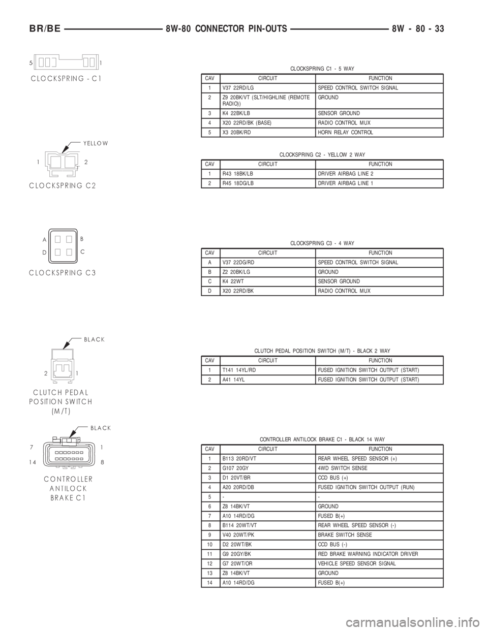
CLOCKSPRING C1-5WAY
CAV CIRCUIT FUNCTION
1 V37 22RD/LG SPEED CONTROL SWITCH SIGNAL
2 Z9 20BK/VT (SLT/HIGHLINE (REMOTE
RADIO))GROUND
3 K4 22BK/LB SENSOR GROUND
4 X20 22RD/BK (BASE) RADIO CONTROL MUX
5 X3 20BK/RD HORN RELAY CONTROL
CLOCKSPRING C2 - YELLOW 2 WAY
CAV CIRCUIT FUNCTION
1 R43 18BK/LB DRIVER AIRBAG LINE 2
2 R45 18DG/LB DRIVER AIRBAG LINE 1
CLOCKSPRING C3-4WAY
CAV CIRCUIT FUNCTION
A V37 22DG/RD SPEED CONTROL SWITCH SIGNAL
B Z2 20BK/LG GROUND
C K4 22WT SENSOR GROUND
D X20 22RD/BK RADIO CONTROL MUX
CLUTCH PEDAL POSITION SWITCH (M/T) - BLACK 2 WAY
CAV CIRCUIT FUNCTION
1 T141 14YL/RD FUSED IGNITION SWITCH OUTPUT (START)
2 A41 14YL FUSED IGNITION SWITCH OUTPUT (START)
CONTROLLER ANTILOCK BRAKE C1 - BLACK 14 WAY
CAV CIRCUIT FUNCTION
1 B113 20RD/VT REAR WHEEL SPEED SENSOR (+)
2 G107 20GY 4WD SWITCH SENSE
3 D1 20VT/BR CCD BUS (+)
4 A20 20RD/DB FUSED IGNITION SWITCH OUTPUT (RUN)
5- -
6 Z8 14BK/VT GROUND
7 A10 14RD/DG FUSED B(+)
8 B114 20WT/VT REAR WHEEL SPEED SENSOR (-)
9 V40 20WT/PK BRAKE SWITCH SENSE
10 D2 20WT/BK CCD BUS (-)
11 G9 20GY/BK RED BRAKE WARNING INDICATOR DRIVER
12 G7 20WT/OR VEHICLE SPEED SENSOR SIGNAL
13 Z8 14BK/VT GROUND
14 A10 14RD/DG FUSED B(+)
BR/BE8W-80 CONNECTOR PIN-OUTS 8W - 80 - 33
Page 1064 of 2889
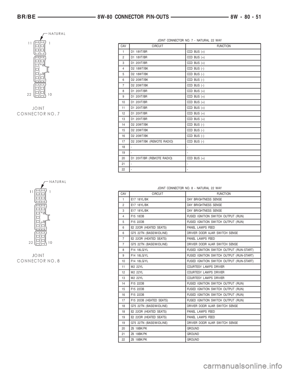
JOINT CONNECTOR NO.7-NATURAL 22 WAY
CAV CIRCUIT FUNCTION
1 D1 18VT/BR CCD BUS (+)
2 D1 18VT/BR CCD BUS (+)
3 D1 20VT/BR CCD BUS (+)
4 D2 18WT/BK CCD BUS (-)
5 D2 18WT/BK CCD BUS (-)
6 D2 20WT/BK CCD BUS (-)
7 D2 20WT/BK CCD BUS (-)
8 D1 20VT/BR CCD BUS (+)
9 D1 20VT/BR CCD BUS (+)
10 D1 20VT/BR CCD BUS (+)
11 D1 20VT/BR CCD BUS (+)
12 D1 20VT/BR CCD BUS (+)
13 D1 20VT/BR CCD BUS (+)
14 D2 20WT/BK CCD BUS (-)
15 D2 20WT/BK CCD BUS (-)
16 D2 20WT/BK CCD BUS (-)
17 D2 20WT/BK (REMOTE RADIO) CCD BUS (-)
18 - -
19 - -
20 D1 20VT/BR (REMOTE RADIO) CCD BUS (+)
21 - -
22 - -
JOINT CONNECTOR NO.8-NATURAL 22 WAY
CAV CIRCUIT FUNCTION
1 E17 18YL/BK DAY BRIGHTNESS SENSE
2 E17 18YL/BK DAY BRIGHTNESS SENSE
3 E17 18YL/BK DAY BRIGHTNESS SENSE
4 F15 18DB FUSED IGNITION SWITCH OUTPUT (RUN)
5 F15 22DB FUSED IGNITION SWITCH OUTPUT (RUN)
6 E2 22OR (HEATED SEATS) PANEL LAMPS FEED
6 G75 22TN (BASE/MIDLINE) DRIVER DOOR AJAR SWITCH SENSE
7 E2 22OR (HEATED SEATS) PANEL LAMPS FEED
7 G75 22TN (BASE/MIDLINE) DRIVER DOOR AJAR SWITCH SENSE
8 F14 18LG/YL FUSED IGNITION SWITCH OUTPUT (RUN-START)
9 F14 18LG/YL FUSED IGNITION SWITCH OUTPUT (RUN-START)
10 F14 18LG/YL FUSED IGNITION SWITCH OUTPUT (RUN-START)
11 M2 22YL COURTESY LAMPS DRIVER
12 M2 22YL COURTESY LAMPS DRIVER
13 M2 22YL COURTESY LAMPS DRIVER
14 F15 22DB FUSED IGNITION SWITCH OUTPUT (RUN)
15 F15 22DB FUSED IGNITION SWITCH OUTPUT (RUN)
16 F15 22DB FUSED IGNITION SWITCH OUTPUT (RUN)
17 F15 20DB (HEATED SEATS) FUSED IGNITION SWITCH OUTPUT (RUN)
18 G75 22TN (BASE/MIDLINE) DRIVER DOOR AJAR SWITCH SENSE
18 E2 22OR (HEATED SEATS) PANEL LAMPS FEED
19 E2 22OR (HEATED SEATS) PANEL LAMPS FEED
19 G75 22TN (BASE/MIDLINE) DRIVER DOOR AJAR SWITCH SENSE
20 Z6 18BK/PK GROUND
21 Z6 18BK/PK GROUND
22 Z6 18BK/PK GROUND
BR/BE8W-80 CONNECTOR PIN-OUTS 8W - 80 - 51
Page 2860 of 2889

ENGINE (1500 AND 2500 MODELS
EXCEPT 8.0L) MAINTENANCE
SCHEDULES, MAINTENANCE
SCHEDULES - LIGHT DUTY...............0-7
ENGINE, 3.9L.........................9-19
ENGINE 3.9L - DESCRIPTION.............9-3
ENGINE 3.9L - INSTALLATION............9-13
ENGINE 3.9L - REMOVAL...............9-12
ENGINE 5.2L - DESCRIPTION............9-60
ENGINE 5.2L - INSTALLATION............9-70
ENGINE 5.2L - REMOVAL...............9-69
ENGINE 5.9L - DESCRIPTION...........9-117
ENGINE 5.9L - INSTALLATION...........9-127
ENGINE 5.9L - REMOVAL..............9-126
ENGINE 5.9L DIESEL - DESCRIPTION.....9-231
ENGINE 8.0L - DESCRIPTION...........9-172
ENGINE 8.0L - INSTALLATION...........9-182
ENGINE 8.0L - REMOVAL..............9-181
ENGINE BLOCK - CLEANING . . 9-142,9-200,9-28,
9-86
ENGINE BLOCK - INSPECTION.....9-142,9-200,
9-267,9-28,9-86
ENGINE BLOCK - STANDARD
PROCEDURE-CYLINDER BLOCK
REFACING..........................9-263
ENGINE BLOCK HEATER - 3.9L/5.2L/
5.9L - DESCRIPTION...................7-45
ENGINE BLOCK HEATER - 3.9L/5.2L/
5.9L - INSTALLATION..................7-45
ENGINE BLOCK HEATER - 3.9L/5.2L/
5.9L - OPERATION.....................7-45
ENGINE BLOCK HEATER - 3.9L/5.2L/
5.9L - REMOVAL......................7-45
ENGINE BLOCK HEATER - 5.9L DIESEL -
DESCRIPTION........................7-47
ENGINE BLOCK HEATER - 5.9L DIESEL -
INSTALLATION........................7-47
ENGINE BLOCK HEATER - 5.9L DIESEL -
OPERATION..........................7-47
ENGINE BLOCK HEATER - 5.9L DIESEL -
REMOVAL...........................7-47
ENGINE BLOCK HEATER - 8.0L -
DESCRIPTION........................7-46
ENGINE BLOCK HEATER - 8.0L -
INSTALLATION........................7-46
ENGINE BLOCK HEATER - 8.0L -
OPERATION..........................7-46
ENGINE BLOCK HEATER - 8.0L -
REMOVAL...........................7-46
ENGINE CONTROL MODULE -
INSTALLATION.......................8E-14
ENGINE CONTROL MODULE - REMOVAL . . 8E-14
ENGINE COOLANT TEMP SENSOR -
3.9L/5.2L/5.9L - DESCRIPTION...........7-48
ENGINE COOLANT TEMP SENSOR -
3.9L/5.2L/5.9L - INSTALLATION..........7-48
ENGINE COOLANT TEMP SENSOR -
3.9L/5.2L/5.9L - OPERATION.............7-48
ENGINE COOLANT TEMP SENSOR -
3.9L/5.2L/5.9L - REMOVAL..............7-48
ENGINE COOLANT THERMOSTAT -
3.9L/5.2L/5.9L - DESCRIPTION...........7-49
ENGINE COOLANT THERMOSTAT -
3.9L/5.2L/5.9L - INSTALLATION
..........7-50
ENGINE COOLANT THERMOSTAT -
3.9L/5.2L/5.9L - OPERATION
.............7-49
ENGINE COOLANT THERMOSTAT -
3.9L/5.2L/5.9L - REMOVAL
..............7-49
ENGINE COOLANT THERMOSTAT - 5.9L
DIESEL - DESCRIPTION
................7-54
ENGINE COOLANT THERMOSTAT - 5.9L
DIESEL - INSTALLATION
................7-55
ENGINE COOLANT THERMOSTAT - 5.9L
DIESEL - OPERATION
..................7-54
ENGINE COOLANT THERMOSTAT - 5.9L
DIESEL - REMOVAL
....................7-55
ENGINE COOLANT THERMOSTAT - 8.0L -
DESCRIPTION
........................7-52
ENGINE COOLANT THERMOSTAT - 8.0L -
INSTALLATION
........................7-53
ENGINE COOLANT THERMOSTAT - 8.0L -
OPERATION
..........................7-52
ENGINE COOLANT THERMOSTAT - 8.0L -
REMOVAL
...........................7-52
ENGINE DATA PLATE - DESCRIPTION
.....9-244
ENGINE DIAGNOSIS - INTRODUCTION -
DIAGNOSIS AND TESTING
.....9-118,9-173,9-3ENGINE DIAGNOSIS - MECHANICAL -
DIAGNOSIS AND TESTING.............9-232
ENGINE (FEDERAL ONLY - 2500 8.0L HD
AND 3500 5.9L& 8.0L MODELS)
MAINTENANCE SCHEDULES -
DESCRIPTION, HEAVY DUTY.............0-17
ENGINE FIRING ORDER, 3.9L V-6
ENGINE..............................8I-2
ENGINE FIRING ORDER, 5.2L/5.9L V-8
ENGINES............................8I-2
ENGINE OIL - DESCRIPTION...........0-3,0-4
ENGINE OIL - STANDARD PROCEDURE . . . 9-104,
9-160,9-217,9-47
ENGINE OIL LEAKS - DIAGNOSIS AND
TESTING.............9-104,9-160,9-215,9-47
ENGINE OIL PRESSURE - DIAGNOSIS
AND TESTING....9-104,9-160,9-215,9-295,9-47
ENGINE PERFORMANCE - INSPECTION . . . 30-16
ENGINE, SPECIAL TOOLS - 5.2L..........9-77
ENGINE, SPECIAL TOOLS - 5.9L.........9-134
ENGINE, SPECIAL TOOLS - 5.9L DIESEL . . 9-244
ENGINE, SPECIAL TOOLS - 8.0L.........9-188
ENGINE, SPECIFICATIONS - 3.9L.........9-14
ENGINE, SPECIFICATIONS - 5.2L.........9-72
ENGINE, SPECIFICATIONS - 5.9L........9-129
ENGINE, SPECIFICATIONS - 8.OL........9-184
ENGINE STARTER MOTOR -
DESCRIPTION.......................8F-39
ENGINE STARTER MOTOR -
INSTALLATION.......................8F-41
ENGINE STARTER MOTOR - OPERATION....8F-39
ENGINE STARTER MOTOR - REMOVAL....8F-40
ENGINE STARTER MOTOR RELAY -
DESCRIPTION.......................8F-42
ENGINE STARTER MOTOR RELAY -
INSTALLATION.......................8F-43
ENGINE STARTER MOTOR RELAY -
OPERATION.........................8F-42
ENGINE STARTER MOTOR RELAY -
REMOVAL..........................8F-43
ENGINE TEMPERATURE GAUGE -
DESCRIPTION.......................8J-19
ENGINE TEMPERATURE GAUGE -
OPERATION.........................8J-19
ENGINES - DESCRIPTION, COMPONENT
MONITORS - DIESEL..................25-18
ENGINES - DESCRIPTION, COMPONENT
MONITORS - GAS....................25-18
ENGINES - DESCRIPTION, FUEL
REQUIREMENTS - GAS..................0-1
ENGINES - DESCRIPTION, V-6/V-8
.......25-35
ENGINES - DIAGNOSIS AND TESTING,
PCV VALVE - V-6/V-8
..................25-36
ENGINES - ENGINE FIRING ORDER,
5.2L/5.9L V-8
.........................8I-2
ENGINES - FUEL SYSTEM PRESSURES,
DIESEL
............................14-58
ENGINES - IGNITION COIL RESISTANCE,
3.9L/5.2L/5.9L
........................8I-3
ENGINES - INSTALLATION, GAS
..........8P-4
ENGINES - OPERATION, GAS
...........25-18
ENGINES - OPERATION, NON-
MONITORED CIRCUITS - GAS
...........25-22
ENGINES - OPERATION, PCM - GAS
......8E-17
ENGINES - OPERATION, V-6/V-8
.........25-35
ENGINES - REMOVAL, GAS
..............8P-4
ENGINES - SPECIFICATIONS, FUEL
SYSTEM PRESSURE - GAS
..............14-4
ENGINES - STANDARD PROCEDURE,
DRAINING COOLING SYSTEM
3.9L/5.2L/5.9L/8.0L
....................7-15
ENGINES - STANDARD PROCEDURE,
REFILLING COOLING SYSTEM
3.9L/5.2L/5.9L/8.0L
....................7-15
ENGINES - VISUAL INSPECTION,
3.9L/5.2L/5.9L
.......................14-28
ENGINE-TO-BODY GROUND STRAP -
INSTALLATION
.......................8A-13
ENGINE-TO-BODY GROUND STRAP -
REMOVAL
..........................8A-13
ENTRY - INSPECTION, KEYLESS
.........30-11
ENTRY SEAT TRACK - INSTALLATION,
EASY
.............................23-142
ENTRY SEAT TRACK - REMOVAL, EASY
. . 23-142
ENTRY SYSTEM - DESCRIPTION,
REMOTE KEYLESS
....................8N-2ENTRY SYSTEM - DIAGNOSIS AND
TESTING, POWER LOCK & REMOTE
KEYLESS............................8N-4
ENTRY SYSTEM - OPERATION, REMOTE
KEYLESS............................8N-3
ENTRY TRANSMITTER - DESCRIPTION,
REMOTE KEYLESS....................8N-7
ENTRY TRANSMITTER - DIAGNOSIS AND
TESTING, REMOTE KEYLESS............8N-7
ENTRY TRANSMITTER - OPERATION,
REMOTE KEYLESS....................8N-7
EQUIPMENT - STANDARD PROCEDURE,
REFRIGERANT SYSTEM SERVICE........24-44
EQUIPMENT IDENTIFICATION PLATE -
DESCRIPTION.....................Intro.-12
ESCUTCHEON - INSTALLATION, HANDLE . . 23-63
ESCUTCHEON - REMOVAL, HANDLE......23-63
EVACUATE - STANDARD PROCEDURE,
REFRIGERANT SYSTEM...............24-45
EVAP SYSTEM - DESCRIPTION..........25-31
EVAP SYSTEM - TORQUE..............25-31
EVAPORATOR - DESCRIPTION, A/C.......24-52
EVAPORATOR - INSTALLATION, A/C......24-53
EVAPORATOR - OPERATION, A/C........24-53
EVAPORATOR - REMOVAL, A/C..........24-53
EVAP/PURGE SOLENOID - DESCRIPTION . . 25-32
EVAP/PURGE SOLENOID - INSTALLATION . 25-32
EVAP/PURGE SOLENOID - REMOVAL.....25-32
EXHAUST MANIFOLD - CLEANING . . 9-112,9-168,
9-225,9-304,9-55
EXHAUST MANIFOLD - DESCRIPTION....9-112,
9-168,9-224,9-55
EXHAUST MANIFOLD - INSPECTION.....9-112,
9-168,9-225,9-304,9-55
EXHAUST MANIFOLD - INSTALLATION . . . 9-113,
9-168,9-225,9-304,9-55
EXHAUST MANIFOLD - OPERATION . 9-112,9-168,
9-224,9-55
EXHAUST MANIFOLD - REMOVAL . . 9-112,9-168,
9-225,9-303,9-55
EXHAUST PIPE - 3.9L/5.2L/5.9L -
INSPECTION.........................11-7
EXHAUST PIPE - 3.9L/5.2L/5.9L -
INSTALLATION........................11-7
EXHAUST PIPE - 3.9L/5.2L/5.9L -
REMOVAL...........................11-7
EXHAUST PIPE - 5.9L DIESEL -
INSPECTION.........................11-9
EXHAUST PIPE - 5.9L DIESEL -
INSTALLATION.......................11-10
EXHAUST PIPE - 5.9L DIESEL -
REMOVAL...........................11-9
EXHAUST PIPE - 5.9L HEAVY DUTY/8.0L
- INSPECTION........................11-9
EXHAUST PIPE - 5.9L HEAVY DUTY/8.0L
- INSTALLATION......................11-9
EXHAUST PIPE - 5.9L HEAVY DUTY/8.0L
- REMOVAL..........................11-8
EXHAUST VENT - INSTALLATION........23-79
EXHAUST VENT - REMOVAL............23-79
EXHAUSTER - INSTALLATION, AIR.......23-77
EXHAUSTER - REMOVAL, AIR...........23-77
EXTENSION HOUSING BUSHING -
INSTALLATION....21-198,21-369,21-544,21-714
EXTENSION HOUSING BUSHING -
REMOVAL.......21-198,21-369,21-544,21-714
EXTENSION HOUSING BUSHING AND
SEAL - INSTALLATION....21-850,21-885,21-921
EXTENSION HOUSING BUSHING AND
SEAL - REMOVAL.......21-850,21-885,21-921
EXTENSION HOUSING SEAL -
INSTALLATION . . . 21-132,21-198,21-369,21-544,
21-715,21-87
EXTENSION HOUSING SEAL - REMOVAL . 21-132,
21-198,21-369,21-544,21-714,21-87
EXTERIOR - DESCRIPTION.............23-86
EXTERIOR - OPERATION...............23-86
EXTERIOR HANDLE - INSTALLATION.....23-70
EXTERIOR HANDLE - REMOVAL.........23-70
EXTERIOR NAME PLATES -
INSTALLATION
.......................23-89
EXTERIOR NAME PLATES - REMOVAL
....23-89
FAILURE - DIAGNOSIS AND TESTING,
CYLINDER HEAD GASKET
. 9-136,9-191,9-22,9-79
FAN - 3.9L/5.2L/5.9L/8.0L - CLEANING,
RADIATOR
...........................7-43
FAN - 3.9L/5.2L/5.9L/8.0L - INSPECTION,
RADIATOR
...........................7-43
BR/BEINDEX 13
Description Group-Page Description Group-Page Description Group-Page
Page 2867 of 2889
INTAKE/EXHAUST VALVES & SEATS -
VALVE SERVICE......................9-195
IN-TANK TRANSMISSION OIL COOLER -
STANDARD PROCEDURE, FLUSHING
COOLER AND TUBES - WITHOUT
RADIATOR...................7-80,7-83,7-86
IN-TANK TRANSMISSION OIL COOLER -
STANDARD PROCEDURE, FLUSHING
COOLERS AND TUBES - WITH
RADIATOR...................7-79,7-83,7-85
INTERIOR - CAUTION................23-118
INTERLOCK SYSTEM - INSPECTION,
SHIFT/CLUTCH.......................30-19
INTERMEDIATE - INSTALLATION, AXLE
SHAFTS.............................3-28
INTERMEDIATE - REMOVAL, AXLE
SHAFTS.............................3-28
INTERMEDIATE AXLE - INSTALLATION.....3-61
INTERMEDIATE AXLE - REMOVAL.........3-60
INTERNATIONAL SYMBOLS -
DESCRIPTION......................Intro.-6
INTERNATIONAL SYMBOLS -
DESCRIPTION.........................0-3
INTRODUCTION - DIAGNOSIS AND
TESTING, ENGINE DIAGNOSIS . . 9-118,9-173,9-3
INTRODUCTION - DIAGNOSIS AND
TESTING-ENGINE DIAGNOSIS............9-61
INVERTED FLARING - STANDARD
PROCEDURE, DOUBLE..................5-8
IOD FUSE - DESCRIPTION...........8W-97-4
IOD FUSE - INSTALLATION...........8W-97-5
IOD FUSE - OPERATION.............8W-97-5
IOD FUSE - REMOVAL................8W-97-5
ISO FLARING - STANDARD PROCEDURE....5-8
ITEMS - INSTALLATION, SHIPPED LOOSE . 30-14
JOINT - DIAGNOSIS AND TESTING,
LOWER BALL........................2-10
JOINT - DIAGNOSIS AND TESTING,
UPPER BALL.........................2-12
JOINT - INSTALLATION, LOWER BALL.....2-25
JOINT - INSTALLATION, UPPER BALL.....2-25
JOINT MOLDING - INSTALLATION, ROOF . . 23-91
JOINT MOLDING - REMOVAL, ROOF......23-91
JOINTS - DISASSEMBLY, SINGLE
CARDAN UNIVERSAL..................3-11
JOINTS - INSTALLATION, SINGLE
CARDAN UNIVERSAL..............3-34,3-66
JOINTS - REMOVAL, SINGLE CARDAN
UNIVERSAL......................3-33,3-65
JOUNCE BUMPER - DESCRIPTION.....2-28,2-9
JOUNCE BUMPER - OPERATION.......2-28,2-9
JOURNAL CLEARANCE - STANDARD
PROCEDURE, CONNECTING ROD
BEARING AND CRANKSHAFT...........9-274
JUMP STARTING - STANDARD
PROCEDURE.........................0-27
JUNCTION BLOCK - DESCRIPTION.....8W-97-6
JUNCTION BLOCK - INSTALLATION....8W-97-7
JUNCTION BLOCK - OPERATION......8W-97-6
JUNCTION BLOCK - REMOVAL........8W-97-6
KEEPER - INSTALLATION, BACKLITE
LATCH ............................23-146
KEEPER - REMOVAL, BACKLITE LATCH . . 23-146
KEY LOCK CYLINDER - DIAGNOSIS AND
TESTING, IGNITION SWITCH............19-10
KEY-IN IGNITION SWITCH -
DESCRIPTION........................19-9
KEYLESS ENTRY - INSPECTION.........30-11
KEYLESS ENTRY SYSTEM -
DESCRIPTION, REMOTE................8N-2
KEYLESS ENTRY SYSTEM - DIAGNOSIS
AND TESTING, POWER LOCK &
REMOTE............................8N-4
KEYLESS ENTRY SYSTEM - OPERATION,
REMOTE............................8N-3
KEYLESS ENTRY TRANSMITTER -
DESCRIPTION, REMOTE................8N-7
KEYLESS ENTRY TRANSMITTER -
DIAGNOSIS AND TESTING, REMOTE......8N-7
KEYLESS ENTRY TRANSMITTER -
OPERATION, REMOTE..................8N-7
KNOB - INSTALLATION, TURNING LOOP
HEIGHT ADJUSTER
...................8O-30
KNOB - REMOVAL, TURNING LOOP
HEIGHT ADJUSTER
...................8O-30
KNUCKLE - DESCRIPTION
............2-20,2-9
KNUCKLE - INSTALLATION
..........2-10,2-20
KNUCKLE - OPERATION
............2-10,2-20KNUCKLE - REMOVAL..............2-10,2-20
LABEL - DESCRIPTION, VECI.........Intro.-10
LABEL - DESCRIPTION, VEHICLE SAFETY
CERTIFICATION....................Intro.-12
LABEL - OPERATION, VECI...........Intro.-10
LABELS - STANDARD PROCEDURE,
INSPECTION - INFORMATION...........30-22
LAMP - DESCRIPTION, READING........8L-36
LAMP - DESCRIPTION, TAIL............8L-29
LAMP - DIAGNOSIS AND TESTING, FOG . . . 8L-9
LAMP - INSTALLATION, CENTER HIGH
MOUNTED STOP......................8L-6
LAMP - INSTALLATION, CLEARANCE......8L-6
LAMP - INSTALLATION, DOME..........8L-33
LAMP - INSTALLATION, FOG............8L-11
LAMP - INSTALLATION, LICENSE PLATE . . 8L-22
LAMP - INSTALLATION, MARKER........8L-23
LAMP - INSTALLATION, OUTBOARD
IDENTIFICATION.....................8L-29
LAMP - INSTALLATION, PARK/TURN
SIGNAL............................8L-29
LAMP - INSTALLATION, READING........8L-36
LAMP - INSTALLATION, TAIL...........8L-30
LAMP - INSTALLATION, UNDERHOOD....8L-32
LAMP - INSTALLATION, VANITY.........8L-37
LAMP - OPERATION, READING..........8L-36
LAMP - OPERATION, TAIL..............8L-29
LAMP - REMOVAL, CENTER HIGH
MOUNTED STOP......................8L-6
LAMP - REMOVAL, CLEARANCE..........8L-6
LAMP - REMOVAL, DOME..............8L-33
LAMP - REMOVAL, FOG...............8L-11
LAMP - REMOVAL, LICENSE PLATE......8L-22
LAMP - REMOVAL, MARKER...........8L-22
LAMP - REMOVAL, OUTBOARD
IDENTIFICATION.....................8L-28
LAMP - REMOVAL, PARK/TURN SIGNAL . . 8L-29
LAMP - REMOVAL, READING...........8L-36
LAMP - REMOVAL, TAIL...............8L-29
LAMP - REMOVAL, UNDERHOOD........8L-31
LAMP - REMOVAL, VANITY.............8L-37
LAMP AND SWITCH - INSTALLATION,
GLOVE BOX.........................8L-35
LAMP AND SWITCH - REMOVAL, GLOVE
BOX ...............................8L-35
LAMP (MIL) - DESCRIPTION,
MALFUNCTION INDICATOR.............8J-24
LAMP (MIL) - OPERATION,
MALFUNCTION INDICATOR.............8J-24
LAMP MODULE - DESCRIPTION,
DAYTIME RUNNING....................8L-9
LAMP MODULE - INSTALLATION,
DAYTIME RUNNING....................8L-9
LAMP MODULE - OPERATION, DAYTIME
RUNNING............................8L-9
LAMP MODULE - REMOVAL, DAYTIME
RUNNING............................8L-9
LAMP SWITCH - DESCRIPTION, BRAKE....8L-4
LAMP SWITCH - DIAGNOSIS AND
TESTING, BRAKE......................8L-5
LAMP SWITCH - INSTALLATION, BRAKE . . . 8L-5
LAMP SWITCH - OPERATION, BRAKE......8L-4
LAMP SWITCH - REMOVAL, BRAKE.......8L-5
LAMP UNIT - ADJUSTMENTS, FOG.......8L-12
LAMP UNIT - INSTALLATION, CENTER
HIGH MOUNTED STOP.................8L-6
LAMP UNIT - INSTALLATION, FOG.......8L-12
LAMP UNIT - INSTALLATION, LICENSE
PLATE .............................8L-22
LAMP UNIT - INSTALLATION, PARK/
TURN SIGNAL.......................8L-29
LAMP UNIT - INSTALLATION, TAIL.......8L-30
LAMP UNIT - INSTALLATION,
UNDERHOOD........................8L-32
LAMP UNIT - REMOVAL, CENTER HIGH
MOUNTED STOP......................8L-6
LAMP UNIT - REMOVAL, FOG...........8L-11
LAMP UNIT - REMOVAL, LICENSE PLATE . . 8L-22
LAMP UNIT - REMOVAL, PARK/TURN
SIGNAL............................8L-29
LAMP UNIT - REMOVAL, TAIL...........8L-30
LAMP UNIT - REMOVAL, UNDERHOOD . . . 8L-32
LASH ADJUSTMENT AND VERIFICATION
- STANDARD PROCEDURE, VALVE
.......9-256
LATCH - ADJUSTMENT
...............23-100
LATCH - ADJUSTMENT, FRONT DOOR
....23-72
LATCH - INSTALLATION
....23-100,23-64,23-72
LATCH - INSTALLATION, SAFETY
.......23-102LATCH - LOWER - INSTALLATION........23-80
LATCH - LOWER - REMOVAL...........23-80
LATCH - REMOVAL........23-100,23-64,23-72
LATCH - REMOVAL, SAFETY...........23-102
LATCH - UPPER - INSTALLATION........23-81
LATCH - UPPER - REMOVAL............23-81
LATCH AND KEEPER - INSTALLATION,
BACKLITE.........................23-146
LATCH AND KEEPER - REMOVAL,
BACKLITE.........................23-146
LATCH HANDLE - INSTALLATION........23-65
LATCH HANDLE - REMOVAL............23-65
LATCH RELEASE CABLE - INSTALLATION . 23-101
LATCH RELEASE CABLE - REMOVAL....23-101
LATCH STRIKER - ADJUSTMENT.......23-102
LATCH STRIKER - INSTALLATION . 23-102,23-65,
23-73
LATCH STRIKER - INSTALLATION, GLOVE
BOX ..............................23-113
LATCH STRIKER - LOWER -
INSTALLATION.......................23-82
LATCH STRIKER - LOWER - REMOVAL....23-82
LATCH STRIKER - REMOVAL.....23-102,23-65,
23-73
LATCH STRIKER - REMOVAL, GLOVE
BOX ..............................23-113
LATCH STRIKER - UPPER -
INSTALLATION.......................23-82
LATCH STRIKER - UPPER - REMOVAL....23-82
LATCH/SAFETY CATCH - INSPECTION,
HOOD..............................30-4
LEAK - DIAGNOSIS AND TESTING,
CONVERTER HOUSING FLUID . . . 21-148,21-319,
21-491,21-662
LEAK DETECTION PUMP - DESCRIPTION . . 25-33
LEAK DETECTION PUMP - INSTALLATION . 25-34
LEAK DETECTION PUMP - REMOVAL.....25-34
LEAK DOWN TEST - DIAGNOSIS AND
TESTING, FUEL PRESSURE..............14-2
LEAKAGE - DIAGNOSIS AND TESTING,
CYLINDER COMBUSTION PRESSURE....9-124,
9-179,9-67,9-9
LEAKAGE - DIAGNOSIS AND TESTING,
INTAKE MANIFOLD.....9-110,9-165,9-222,9-53
LEAKAGE - DIAGNOSIS AND TESTING,
POWER STEERING GEAR..............19-14
LEAKAGE - DIAGNOSIS AND TESTING,
PUMP.............................19-31
LEAKS - DIAGNOSIS AND TESTING,
COOLING SYSTEM.....................7-5
LEAKS - DIAGNOSIS AND TESTING,
ENGINE OIL...........9-104,9-160,9-215,9-47
LEAKS - DIAGNOSIS AND TESTING,
HIGH-PRESSURE FUEL LINE............14-74
LEAKS - DIAGNOSIS AND TESTING,
REAR SEAL AREA.....................9-10
LEAKS - DIAGNOSIS AND TESTING,
REFRIGERANT SYSTEM...............24-43
LEAKS - DIAGNOSIS AND TESTING,
WATER .............................23-2
LEAKS - STANDARD PROCEDURES,
REPAIRING..........................22-8
LEFT FRONT FENDER - INSTALLATION....23-93
LEFT FRONT FENDER - REMOVAL.......23-92
LEVEL - DIAGNOSIS AND TESTING,
EFFECTS OF INCORRECT FLUID . . 21-199,21-370,
21-545,21-715
LEVEL - STANDARD PROCEDURE,
BRAKE FLUID........................5-14
LEVEL - STANDARD PROCEDURE,
CHECKING BATTERY ELECTROLYTE.......8F-8
LEVEL - STANDARD PROCEDURE,
REFRIGERANT OIL...................24-57
LEVEL CHECK - STANDARD
PROCEDURE, COOLANT................7-16
LEVEL CHECK - STANDARD
PROCEDURE, FLUID.....21-199,21-370,21-545,
21-715
LEVEL, OIL - STANDARD PROCEDURE-
ENGINE OIL
.........................9-295
LEVEL SENDING UNIT / SENSOR -
DESCRIPTION, FUEL
..............14-7,14-73
LEVEL SENDING UNIT / SENSOR -
INSTALLATION, FUEL
..................14-9
LEVEL SENDING UNIT / SENSOR -
OPERATION, FUEL
................14-7,14-73
LEVEL SENDING UNIT / SENSOR -
REMOVAL, FUEL
......................14-8
20 INDEXBR/BE
Description Group-Page Description Group-Page Description Group-Page
Page 2876 of 2889
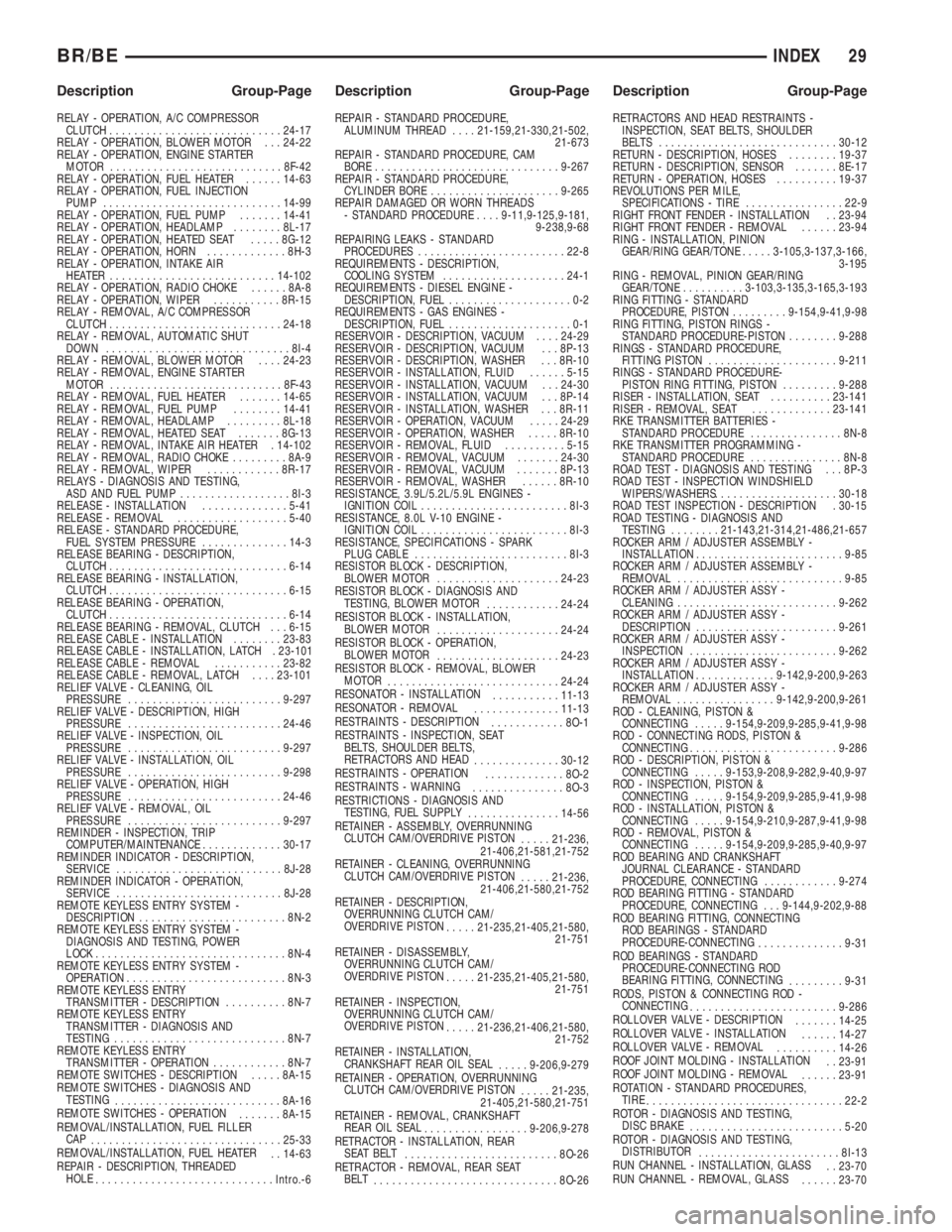
RELAY - OPERATION, A/C COMPRESSOR
CLUTCH............................24-17
RELAY - OPERATION, BLOWER MOTOR . . . 24-22
RELAY - OPERATION, ENGINE STARTER
MOTOR............................8F-42
RELAY - OPERATION, FUEL HEATER......14-63
RELAY - OPERATION, FUEL INJECTION
PUMP.............................14-99
RELAY - OPERATION, FUEL PUMP.......14-41
RELAY - OPERATION, HEADLAMP........8L-17
RELAY - OPERATION, HEATED SEAT.....8G-12
RELAY - OPERATION, HORN.............8H-3
RELAY - OPERATION, INTAKE AIR
HEATER ...........................14-102
RELAY - OPERATION, RADIO CHOKE......8A-8
RELAY - OPERATION, WIPER...........8R-15
RELAY - REMOVAL, A/C COMPRESSOR
CLUTCH............................24-18
RELAY - REMOVAL, AUTOMATIC SHUT
DOWN..............................8I-4
RELAY - REMOVAL, BLOWER MOTOR....24-23
RELAY - REMOVAL, ENGINE STARTER
MOTOR............................8F-43
RELAY - REMOVAL, FUEL HEATER.......14-65
RELAY - REMOVAL, FUEL PUMP........14-41
RELAY - REMOVAL, HEADLAMP.........8L-18
RELAY - REMOVAL, HEATED SEAT.......8G-13
RELAY - REMOVAL, INTAKE AIR HEATER . 14-102
RELAY - REMOVAL, RADIO CHOKE.........8A-9
RELAY - REMOVAL, WIPER............8R-17
RELAYS - DIAGNOSIS AND TESTING,
ASD AND FUEL PUMP..................8I-3
RELEASE - INSTALLATION..............5-41
RELEASE - REMOVAL..................5-40
RELEASE - STANDARD PROCEDURE,
FUEL SYSTEM PRESSURE..............14-3
RELEASE BEARING - DESCRIPTION,
CLUTCH.............................6-14
RELEASE BEARING - INSTALLATION,
CLUTCH.............................6-15
RELEASE BEARING - OPERATION,
CLUTCH.............................6-14
RELEASE BEARING - REMOVAL, CLUTCH . . . 6-15
RELEASE CABLE - INSTALLATION........23-83
RELEASE CABLE - INSTALLATION, LATCH . 23-101
RELEASE CABLE - REMOVAL...........23-82
RELEASE CABLE - REMOVAL, LATCH....23-101
RELIEF VALVE - CLEANING, OIL
PRESSURE.........................9-297
RELIEF VALVE - DESCRIPTION, HIGH
PRESSURE.........................24-46
RELIEF VALVE - INSPECTION, OIL
PRESSURE.........................9-297
RELIEF VALVE - INSTALLATION, OIL
PRESSURE.........................9-298
RELIEF VALVE - OPERATION, HIGH
PRESSURE.........................24-46
RELIEF VALVE - REMOVAL, OIL
PRESSURE.........................9-297
REMINDER - INSPECTION, TRIP
COMPUTER/MAINTENANCE.............30-17
REMINDER INDICATOR - DESCRIPTION,
SERVICE...........................8J-28
REMINDER INDICATOR - OPERATION,
SERVICE...........................8J-28
REMOTE KEYLESS ENTRY SYSTEM -
DESCRIPTION........................8N-2
REMOTE KEYLESS ENTRY SYSTEM -
DIAGNOSIS AND TESTING, POWER
LOCK...............................8N-4
REMOTE KEYLESS ENTRY SYSTEM -
OPERATION..........................8N-3
REMOTE KEYLESS ENTRY
TRANSMITTER - DESCRIPTION..........8N-7
REMOTE KEYLESS ENTRY
TRANSMITTER - DIAGNOSIS AND
TESTING............................8N-7
REMOTE KEYLESS ENTRY
TRANSMITTER - OPERATION............8N-7
REMOTE SWITCHES - DESCRIPTION.....8A-15
REMOTE SWITCHES - DIAGNOSIS AND
TESTING
...........................8A-16
REMOTE SWITCHES - OPERATION
.......8A-15
REMOVAL/INSTALLATION, FUEL FILLER
CAP
...............................25-33
REMOVAL/INSTALLATION, FUEL HEATER
. . 14-63
REPAIR - DESCRIPTION, THREADED
HOLE
.............................Intro.-6REPAIR - STANDARD PROCEDURE,
ALUMINUM THREAD....21-159,21-330,21-502,
21-673
REPAIR - STANDARD PROCEDURE, CAM
BORE..............................9-267
REPAIR - STANDARD PROCEDURE,
CYLINDER BORE.....................9-265
REPAIR DAMAGED OR WORN THREADS
- STANDARD PROCEDURE....9-11,9-125,9-181,
9-238,9-68
REPAIRING LEAKS - STANDARD
PROCEDURES........................22-8
REQUIREMENTS - DESCRIPTION,
COOLING SYSTEM....................24-1
REQUIREMENTS - DIESEL ENGINE -
DESCRIPTION, FUEL....................0-2
REQUIREMENTS - GAS ENGINES -
DESCRIPTION, FUEL....................0-1
RESERVOIR - DESCRIPTION, VACUUM....24-29
RESERVOIR - DESCRIPTION, VACUUM . . . 8P-13
RESERVOIR - DESCRIPTION, WASHER . . . 8R-10
RESERVOIR - INSTALLATION, FLUID......5-15
RESERVOIR - INSTALLATION, VACUUM . . . 24-30
RESERVOIR - INSTALLATION, VACUUM . . . 8P-14
RESERVOIR - INSTALLATION, WASHER . . . 8R-11
RESERVOIR - OPERATION, VACUUM.....24-29
RESERVOIR - OPERATION, WASHER.....8R-10
RESERVOIR - REMOVAL, FLUID..........5-15
RESERVOIR - REMOVAL, VACUUM.......24-30
RESERVOIR - REMOVAL, VACUUM.......8P-13
RESERVOIR - REMOVAL, WASHER......8R-10
RESISTANCE, 3.9L/5.2L/5.9L ENGINES -
IGNITION COIL........................8I-3
RESISTANCE, 8.0L V-10 ENGINE -
IGNITION COIL........................8I-3
RESISTANCE, SPECIFICATIONS - SPARK
PLUG CABLE.........................8I-3
RESISTOR BLOCK - DESCRIPTION,
BLOWER MOTOR....................24-23
RESISTOR BLOCK - DIAGNOSIS AND
TESTING, BLOWER MOTOR
............24-24
RESISTOR BLOCK - INSTALLATION,
BLOWER MOTOR
....................24-24
RESISTOR BLOCK - OPERATION,
BLOWER MOTOR
....................24-23
RESISTOR BLOCK - REMOVAL, BLOWER
MOTOR
............................24-24
RESONATOR - INSTALLATION
...........11-13
RESONATOR - REMOVAL
..............11-13
RESTRAINTS - DESCRIPTION
............8O-1
RESTRAINTS - INSPECTION, SEAT
BELTS, SHOULDER BELTS,
RETRACTORS AND HEAD
..............30-12
RESTRAINTS - OPERATION
.............8O-2
RESTRAINTS - WARNING
...............8O-3
RESTRICTIONS - DIAGNOSIS AND
TESTING, FUEL SUPPLY
...............14-56
RETAINER - ASSEMBLY, OVERRUNNING
CLUTCH CAM/OVERDRIVE PISTON
.....21-236,
21-406,21-581,21-752
RETAINER - CLEANING, OVERRUNNING
CLUTCH CAM/OVERDRIVE PISTON
.....21-236,
21-406,21-580,21-752
RETAINER - DESCRIPTION,
OVERRUNNING CLUTCH CAM/
OVERDRIVE PISTON
.....21-235,21-405,21-580,
21-751
RETAINER - DISASSEMBLY,
OVERRUNNING CLUTCH CAM/
OVERDRIVE PISTON
.....21-235,21-405,21-580,
21-751
RETAINER - INSPECTION,
OVERRUNNING CLUTCH CAM/
OVERDRIVE PISTON
.....21-236,21-406,21-580,
21-752
RETAINER - INSTALLATION,
CRANKSHAFT REAR OIL SEAL
.....9-206,9-279
RETAINER - OPERATION, OVERRUNNING
CLUTCH CAM/OVERDRIVE PISTON
.....21-235,
21-405,21-580,21-751
RETAINER - REMOVAL, CRANKSHAFT
REAR OIL SEAL
.................9-206,9-278
RETRACTOR - INSTALLATION, REAR
SEAT BELT
.........................8O-26
RETRACTOR - REMOVAL, REAR SEAT
BELT
..............................8O-26RETRACTORS AND HEAD RESTRAINTS -
INSPECTION, SEAT BELTS, SHOULDER
BELTS .............................30-12
RETURN - DESCRIPTION, HOSES........19-37
RETURN - DESCRIPTION, SENSOR.......8E-17
RETURN - OPERATION, HOSES..........19-37
REVOLUTIONS PER MILE,
SPECIFICATIONS - TIRE................22-9
RIGHT FRONT FENDER - INSTALLATION . . 23-94
RIGHT FRONT FENDER - REMOVAL......23-94
RING - INSTALLATION, PINION
GEAR/RING GEAR/TONE.....3-105,3-137,3-166,
3-195
RING - REMOVAL, PINION GEAR/RING
GEAR/TONE..........3-103,3-135,3-165,3-193
RING FITTING - STANDARD
PROCEDURE, PISTON.........9-154,9-41,9-98
RING FITTING, PISTON RINGS -
STANDARD PROCEDURE-PISTON........9-288
RINGS - STANDARD PROCEDURE,
FITTING PISTON.....................9-211
RINGS - STANDARD PROCEDURE-
PISTON RING FITTING, PISTON.........9-288
RISER - INSTALLATION, SEAT..........23-141
RISER - REMOVAL, SEAT.............23-141
RKE TRANSMITTER BATTERIES -
STANDARD PROCEDURE...............8N-8
RKE TRANSMITTER PROGRAMMING -
STANDARD PROCEDURE...............8N-8
ROAD TEST - DIAGNOSIS AND TESTING . . . 8P-3
ROAD TEST - INSPECTION WINDSHIELD
WIPERS/WASHERS....................30-18
ROAD TEST INSPECTION - DESCRIPTION . 30-15
ROAD TESTING - DIAGNOSIS AND
TESTING........21-143,21-314,21-486,21-657
ROCKER ARM / ADJUSTER ASSEMBLY -
INSTALLATION........................9-85
ROCKER ARM / ADJUSTER ASSEMBLY -
REMOVAL...........................9-85
ROCKER ARM / ADJUSTER ASSY -
CLEANING..........................9-262
ROCKER ARM / ADJUSTER ASSY -
DESCRIPTION.......................9-261
ROCKER ARM / ADJUSTER ASSY -
INSPECTION........................9-262
ROCKER ARM / ADJUSTER ASSY -
INSTALLATION.............9-142,9-200,9-263
ROCKER ARM / ADJUSTER ASSY -
REMOVAL................9-142,9-200,9-261
ROD - CLEANING, PISTON &
CONNECTING.....9-154,9-209,9-285,9-41,9-98
ROD - CONNECTING RODS, PISTON &
CONNECTING........................9-286
ROD - DESCRIPTION, PISTON &
CONNECTING.....9-153,9-208,9-282,9-40,9-97
ROD - INSPECTION, PISTON &
CONNECTING.....9-154,9-209,9-285,9-41,9-98
ROD - INSTALLATION, PISTON &
CONNECTING.....9-154,9-210,9-287,9-41,9-98
ROD - REMOVAL, PISTON &
CONNECTING.....9-154,9-209,9-285,9-40,9-97
ROD BEARING AND CRANKSHAFT
JOURNAL CLEARANCE - STANDARD
PROCEDURE, CONNECTING............9-274
ROD BEARING FITTING - STANDARD
PROCEDURE, CONNECTING . . . 9-144,9-202,9-88
ROD BEARING FITTING, CONNECTING
ROD BEARINGS - STANDARD
PROCEDURE-CONNECTING
..............9-31
ROD BEARINGS - STANDARD
PROCEDURE-CONNECTING ROD
BEARING FITTING, CONNECTING
.........9-31
RODS, PISTON & CONNECTING ROD -
CONNECTING
........................9-286
ROLLOVER VALVE - DESCRIPTION
.......14-25
ROLLOVER VALVE - INSTALLATION
......14-27
ROLLOVER VALVE - REMOVAL
..........14-26
ROOF JOINT MOLDING - INSTALLATION
. . 23-91
ROOF JOINT MOLDING - REMOVAL
......23-91
ROTATION - STANDARD PROCEDURES,
TIRE
................................22-2
ROTOR - DIAGNOSIS AND TESTING,
DISC BRAKE
.........................5-20
ROTOR - DIAGNOSIS AND TESTING,
DISTRIBUTOR
.......................8I-13
RUN CHANNEL - INSTALLATION, GLASS
. . 23-70
RUN CHANNEL - REMOVAL, GLASS
......23-70
BR/BEINDEX 29
Description Group-Page Description Group-Page Description Group-Page