steering column DODGE RAM 2001 Service Repair Manual
[x] Cancel search | Manufacturer: DODGE, Model Year: 2001, Model line: RAM, Model: DODGE RAM 2001Pages: 2889, PDF Size: 68.07 MB
Page 287 of 2889
PEDAL
DESCRIPTION
The brake booster is operated by a suspended type
brake pedal. The pedal pivots on a shaft located in a
mounting bracket attached to the dash panel. The
pedal shaft is supported by bushings in the pedal
and mounting bracket. The brake pedal is attached
to the booster push rod.
OPERATION
When the pedal is depressed, the primary booster
push rod is depressed which move the booster sec-
ondary rod. The booster secondary rod depress the
master cylinder piston.
REMOVAL
(1) Remove knee bolster, (Refer to 23 - BODY/IN-
STRUMENT PANEL/STEERING COLUMN OPEN-
ING COVER - REMOVAL).
(2) Remove brake lamp switch, (Refer to 8 - ELEC-
TRICAL/LAMPS/LIGHTING - EXTERIOR/BRAKE
LAMP SWITCH - REMOVAL).
(3) Remove switches from tabs on brake lamp
switch bracket.
(4) Remove brake lamp switch bracket bolts and
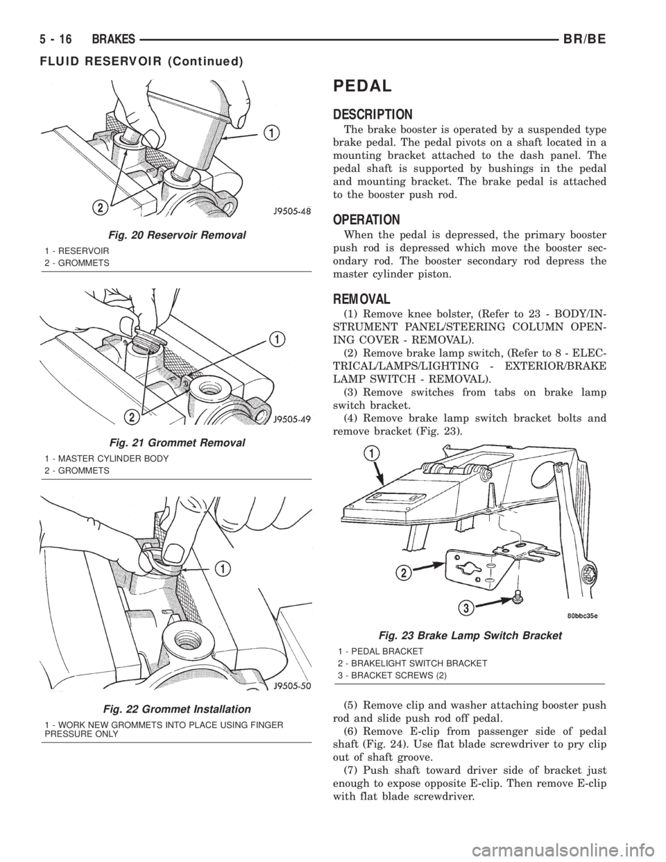
remove bracket (Fig. 23).
(5) Remove clip and washer attaching booster push
rod and slide push rod off pedal.
(6) Remove E-clip from passenger side of pedal
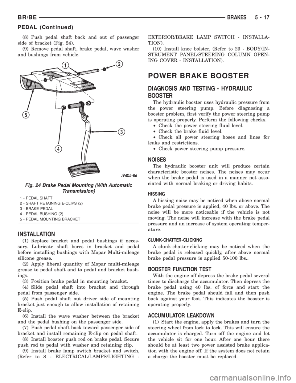
shaft (Fig. 24). Use flat blade screwdriver to pry clip
out of shaft groove.
(7) Push shaft toward driver side of bracket just
enough to expose opposite E-clip. Then remove E-clip
with flat blade screwdriver.
Fig. 20 Reservoir Removal
1 - RESERVOIR
2 - GROMMETS
Fig. 21 Grommet Removal
1 - MASTER CYLINDER BODY
2 - GROMMETS
Fig. 22 Grommet Installation
1 - WORK NEW GROMMETS INTO PLACE USING FINGER
PRESSURE ONLY
Fig. 23 Brake Lamp Switch Bracket
1 - PEDAL BRACKET
2 - BRAKELIGHT SWITCH BRACKET
3 - BRACKET SCREWS (2)
5 - 16 BRAKESBR/BE
FLUID RESERVOIR (Continued)
Page 288 of 2889
(8) Push pedal shaft back and out of passenger
side of bracket (Fig. 24).
(9) Remove pedal shaft, brake pedal, wave washer
and bushings from vehicle.
INSTALLATION
(1) Replace bracket and pedal bushings if neces-
sary. Lubricate shaft bores in bracket and pedal
before installing bushings with Mopar Multi-mileage
silicone grease.
(2) Apply liberal quantity of Mopar multi-mileage
grease to pedal shaft and to pedal and bracket bush-
ings.
(3) Position brake pedal in mounting bracket.
(4) Slide pedal shaft into bracket and through
pedal from passenger side.
(5) Push pedal shaft out driver side of mounting
bracket just enough to allow installation of retaining
E-clip.
(6) Install the wave washer between the bracket
and the pedal bushing on the passenger side.
(7) Push pedal shaft back toward passenger side of
bracket and install remaining E-clip on pedal shaft.
(8) Install booster push rod on brake pedal. Secure
push rod to pedal with washer and retaining clip.
(9) Install brake lamp switch bracket and switch,
(Refer to 8 - ELECTRICAL/LAMPS/LIGHTING -EXTERIOR/BRAKE LAMP SWITCH - INSTALLA-
TION).
(10) Install knee bolster, (Refer to 23 - BODY/IN-
STRUMENT PANEL/STEERING COLUMN OPEN-
ING COVER - INSTALLATION).
POWER BRAKE BOOSTER
DIAGNOSIS AND TESTING - HYDRAULIC
BOOSTER
The hydraulic booster uses hydraulic pressure from
the power steering pump. Before diagnosing a
booster problem, first verify the power steering pump
is operating properly. Perform the following checks.
²Check the power steering fluid level.
²Check the brake fluid level.
²Check all power steering hoses and lines for
leaks and restrictions.
²Check power steering pump pressure.
NOISES
The hydraulic booster unit will produce certain
characteristic booster noises. The noises may occur
when the brake pedal is used in a manner not asso-
ciated with normal braking or driving habits.
HISSING
A hissing noise may be noticed when above normal
brake pedal pressure is applied, 40 lbs. or above. The
noise will be more noticeable if the vehicle is not
moving. The noise will increase with the brake pedal
pressure and an increase of system operating temper-
ature.
CLUNK-CHATTER-CLICKING
A clunk-chatter-clicking may be noticed when the
brake pedal is released quickly, after above normal
brake pedal pressure is applied 50-100 lbs..
BOOSTER FUNCTION TEST
With the engine off depress the brake pedal several
times to discharge the accumulator. Then depress the
brake pedal using 40 lbs. of force and start the
engine. The brake pedal should fall and then push
back against your foot. This indicates the booster is
operating properly.
ACCUMULATOR LEAKDOWN
(1) Start the engine, apply the brakes and turn the
steering wheel from lock to lock. This will ensure the
accumulator is charged. Turn off the engine and let
the vehicle sit for one hour. After one hour there
should be at least two power assisted brake applica-
tion with the engine off. If the system does not retain
a charge the booster must be replaced.
Fig. 24 Brake Pedal Mounting (With Automatic
Transmission)
1 - PEDAL SHAFT
2 - SHAFT RETAINING E-CLIPS (2)
3 - BRAKE PEDAL
4 - PEDAL BUSHING (2)
5 - PEDAL MOUNTING BRACKET
BR/BEBRAKES 5 - 17
PEDAL (Continued)
Page 291 of 2889
INSTALLATION
(1) Install the hydraulic booster and tighten the
mounting nuts to 28 N´m (21 ft. lbs.).
(2) Install the booster push rod, washer and clip
onto the brake pedal.
(3) Install the master cylinder on the mounting
studs. and tighten the mounting nuts to 23 N´m (17
ft. lbs.).
(4) Install the brake lines to the master cylinder
and tighten to 19-200 N´m (170-200 in. lbs.).
(5) Install the hydraulic booster line bracket onto
the master cylinder mounting studs.
(6) Install the master cylinder mounting nuts and
tighten to 23 N´m (17 ft. lbs.).
(7) Install the hydraulic booster pressure lines to
the bracket and booster.
(8) Tighten the pressure lines to 28 N´m (21 ft.
lbs.).
NOTE: Inspect o-rings on the pressure line fittings
to insure they are in good condition before installa-
tion. Replace o-rings if necessary.
(9) Install the return hose to the booster.
(10) Bleed base brake system, (Refer to 5 -
BRAKES/HYDRAULIC/MECHANICAL - STAN-
DARD PROCEDURE).
(11) Fill the power steering pump with fluid,
(Refer to 19 - STEERING/PUMP - STANDARD PRO-
CEDURE).
CAUTION: Use only MOPAR power steering fluid or
equivalent. Do not use automatic transmission fluid
and do not overfill.(12) Bleed the hydraulic booster.
ROTORS
DIAGNOSIS AND TESTINGÐDISC BRAKE
ROTOR
The rotor braking surfaces should not be refinished
unless necessary.
Light surface rust and scale can be removed with a
lathe equipped with dual sanding discs. The rotor
surfaces can be restored by machining with a disc
brake lathe if surface scoring and wear are light.
Replace the rotor for the following conditions:
²Severely Scored
²Tapered
²Hard Spots
²Cracked
²Below Minimum Thickness
ROTOR MINIMUM THICKNESS
Measure rotor thickness at the center of the brake
shoe contact surface. Replace the rotor if below min-
imum thickness, or if machining would reduce thick-
ness below the allowable minimum.
Rotor minimum thickness is usually specified on
the rotor hub. The specification is either stamped or
cast into the hub surface.
ROTOR RUNOUT
Check rotor lateral runout with dial indicator
C-3339 (Fig. 29). Excessive lateral runout will cause
brake pedal pulsation and rapid, uneven wear of the
brake shoes. Position the dial indicator plunger
approximately 25.4 mm (1 in.) inward from the rotor
edge.
NOTE: Be sure wheel bearing has zero end play
before checking rotor runout.
Maximum allowable rotor runout is 0.127 mm
(0.005 in.).
ROTOR THICKNESS VARIATION
Variations in rotor thickness will cause pedal pul-
sation, noise and shudder.
Measure rotor thickness at 6 to 12 points around
the rotor face (Fig. 30).
Position the micrometer approximately 25.4 mm (1
in.) from the rotor outer circumference for each mea-
surement.
Thickness should notvaryby more than 0.025 mm
(0.001 in.) from point-to-point on the rotor. Machine
or replace the rotor if necessary.
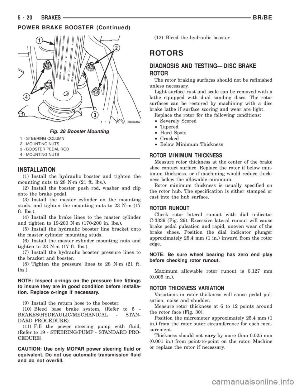
Fig. 28 Booster Mounting
1 - STEERING COLUMN
2 - MOUNTING NUTS
3 - BOOSTER PEDAL ROD
4 - MOUNTING NUTS
5 - 20 BRAKESBR/BE
POWER BRAKE BOOSTER (Continued)
Page 307 of 2889
OPERATION - 2500/3500 WITH REAR DISC
BRAKES
To apply the parking brake the pedal is depressed.
This creates tension in the cable which pulls forward
on the park brake lever. The lever pushes the park
brake shoes outward and into contact with the drum
section of the rotor. The contact of shoe to rotor parks
the vehicle.
A torsion locking mechanism is used to hold the
pedal in an applied position. Parking brake release is
accomplished by the hand release.
A parking brake switch is mounted on the parking
brake lever and is actuated by movement of the
lever. The switch, which is in circuit with the red
warning light in the dash, will illuminate the warn-
ing light whenever the parking brake is applied.
Parking brake adjustment is controlled by a cable
tensioner mechanism. The cable tensioner, once
adjusted at the factory, should not need further
adjustment under normal circumstances. Adjustment
may be required if a new tensioner, or cables are
installed, or disconnected.
OPERATION - (1500 models) (Early 2500/3500
models with rear drum brakes)
To apply the parking brakes, the pedal is
depressed. This pulls the rear brake shoe actuating
levers forward. As the actuating lever is pulled for-
ward, the parking brake strut or cam, exerts a linear
force against the primary brake shoe. This action
presses the primary shoe into contact with the drum.
Once the primary shoe contacts the drum, force is
exerted through the strut/cam. This force is trans-
ferred through the strut/cam to the secondary brake
shoe causing it to pivot into the drum as well.
A torsion locking mechanism is used to hold the
pedal in an applied position. Parking brake release is
accomplished by the hand release.
A parking brake switch is mounted on the parking
brake lever and is actuated by movement of the
lever. The switch, which is in circuit with the red
warning light in the dash, will illuminate the warn-
ing light whenever the parking brake is applied.
Parking brake adjustment is controlled by a cable
tensioner mechanism. The cable tensioner, once
adjusted at the factory, should not need further
adjustment under normal circumstances. Adjustment
may be required if a new tensioner, or cables are
installed, or disconnected.
PEDAL
REMOVAL
(1) Release the parking brake.
(2) Raise the vehicle.(3) Loosen the cable tensioner nut at the equalizer
to create slack in the front cable.
(4) Lower the vehicle.
(5) Remove the knee bolster, (Refer to 23 - BODY/
INSTRUMENT PANEL/STEERING COLUMN
OPENING COVER - REMOVAL).
(6) Disconnect the brake lamp wire from the
switch on the pedal assembly.
(7) Roll the carpet back, loosen the front cable
grommet from the floorpan and the cable retainer.
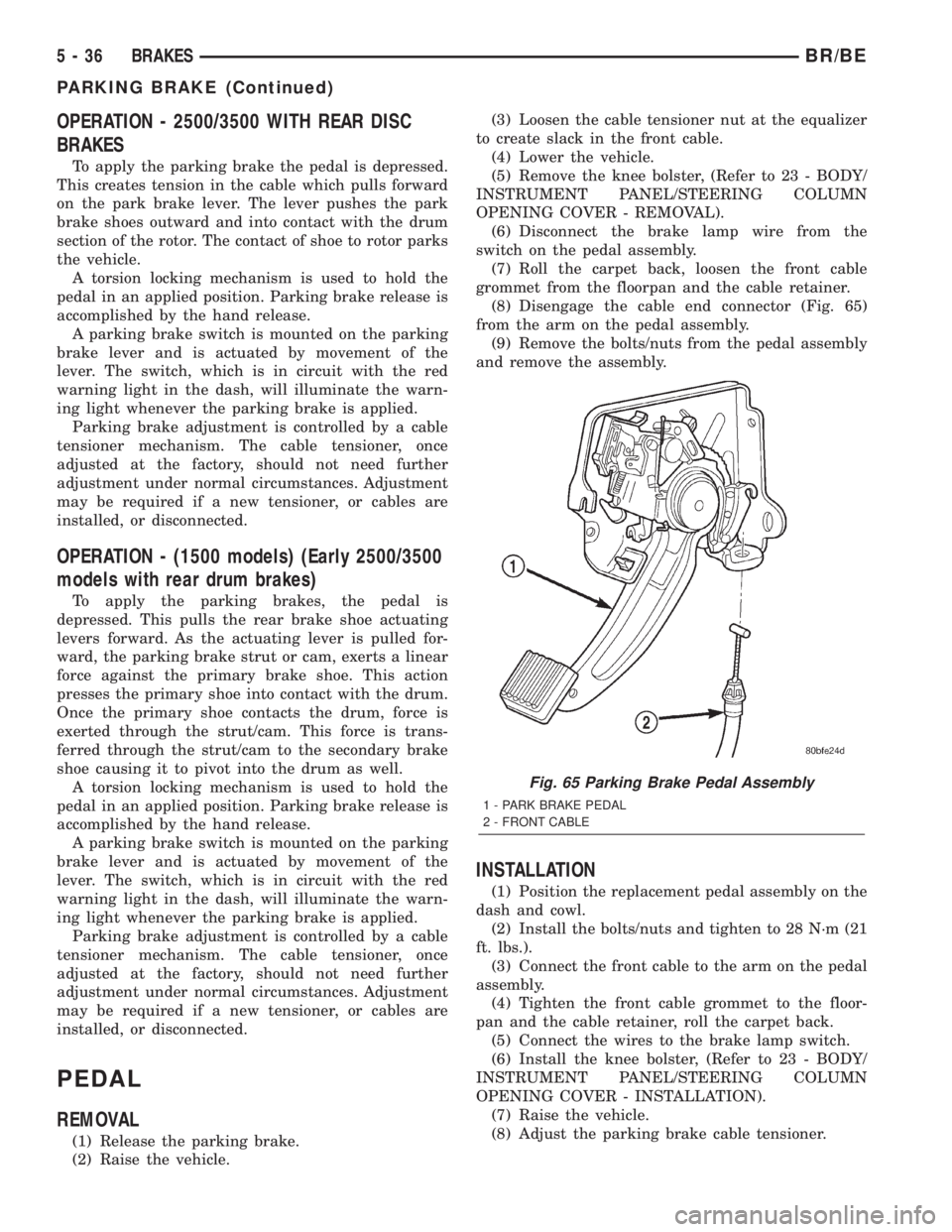
(8) Disengage the cable end connector (Fig. 65)
from the arm on the pedal assembly.
(9) Remove the bolts/nuts from the pedal assembly
and remove the assembly.
INSTALLATION
(1) Position the replacement pedal assembly on the
dash and cowl.
(2) Install the bolts/nuts and tighten to 28 N´m (21
ft. lbs.).
(3) Connect the front cable to the arm on the pedal
assembly.
(4) Tighten the front cable grommet to the floor-
pan and the cable retainer, roll the carpet back.
(5) Connect the wires to the brake lamp switch.
(6) Install the knee bolster, (Refer to 23 - BODY/
INSTRUMENT PANEL/STEERING COLUMN
OPENING COVER - INSTALLATION).
(7) Raise the vehicle.
(8) Adjust the parking brake cable tensioner.
Fig. 65 Parking Brake Pedal Assembly
1 - PARK BRAKE PEDAL
2 - FRONT CABLE
5 - 36 BRAKESBR/BE
PARKING BRAKE (Continued)
Page 425 of 2889
Refer to Electrical, Restraints for more information
on the clockspring. Refer to Electrical, Body Control/
Central Control Module for more information on the
Central Timer Module. Refer to the appropriate wir-
ing information. The wiring information includes wir-
ing diagrams, proper wire and connector repair
procedures, details of wire harness routing and
retention, connector pin-out information and location
views for the various wire harness connectors, splices
and grounds. Following are general descriptions of
the remaining major components in the standard and
optional factory-installed audio systems.
OPERATION
See the owner's manual in the vehicle glove box for
more information on the features, use and operation
of each of the available audio systems.
CENTRAL TIMER MODULE
The high-line or premium Central Timer Module
(CTM) can also control some features of the audio
system when the vehicle is equipped with the
optional RAZ radio receiver and remote radio
switches. A high-line CTM is used on high-line ver-
sions of this vehicle. A premium CTM is used on
vehicles equipped with the optional heated seats. The
CTM combines the functions of a chime/buzzer mod-
ule, an intermittent wipe module, an illuminated
entry module, a remote keyless entry module, and a
vehicle theft security system module in a single unit.
The high-line or premium CTM also controls and
integrates many of the additional electronic functions
and features included on models with this option.The RAZ radio receiver with a remote radio switch
option is one of the features that the CTM controls.
The CTM is programmed to send switch status mes-
sages over the Chrysler Collision Detection (CCD)
data bus to control the volume, seek, and pre-set sta-
tion advance functions of the RAZ radio receiver. The
CTM monitors the status of the remote radio
switches located on the steering wheel through a
hard wired circuit. The CTM then sends the proper
switch status messages to the radio receiver. The
electronic circuitry within the radio receiver responds
to the switch status messages it receives by adjusting
the radio settings as requested.
Refer to Electrical, Body Control/Central Timer
Module for more information on the high-line CTM.
Refer to Remote Radio Switch in Description and
Operation for more information on this component.
In addition, radio receivers connected to the CCD
data bus have several audio system functions that
can be diagnosed using a DRBIIItscan tool. Refer to
the proper Diagnostic Procedures manual for more
information on DRBIIIttesting of the audio systems.
DIAGNOSIS AND TESTING - AUDIO
WARNING: ON VEHICLES EQUIPPED WITH AIR-
BAGS, REFER TO ELECTRICAL, RESTRAINTS
BEFORE ATTEMPTING ANY STEERING WHEEL,
STEERING COLUMN, OR INSTRUMENT PANEL
COMPONENT DIAGNOSIS OR SERVICE. FAILURE
TO TAKE THE PROPER PRECAUTIONS COULD
RESULT IN ACCIDENTAL AIRBAG DEPLOYMENT
AND POSSIBLE PERSONAL INJURY.
8A - 2 AUDIOBR/BE
AUDIO (Continued)
Page 428 of 2889
commercial radio stations in both the Amplitude
Modulating (AM) and Frequency Modulating (FM)
frequency ranges. These electromagnetic radio fre-
quency signals induce small electrical modulations
into the antenna as they move past the mast. The
antenna body transfers the weak electromagnetic
radio waves induced into the rigid antenna mast into
the center conductor of the flexible primary antenna
coaxial cable. The braided outer shield of the
antenna coaxial cable is grounded through both the
antenna body and the radio chassis, effectively
shielding the radio waves as they are conducted to
the radio. The radio then tunes and amplifies the
weak radio signals into stronger electrical signals in
order to operate the audio system speakers.
The antenna body includes an integral flange that
mates with and grounds the antenna body to the
underside of the fender panel sheet metal. Above the
fender panel, the antenna body has a short nipple
that is externally threaded to accept the antenna cap
nut. Inside the nipple is a plastic insulator tube, and
inside this insulator is an internally threaded metal
receptacle that accepts the adapter stud on the bot-
tom of the antenna mast. The antenna adapter
serves as an above fender interface to mount and
secure the antenna body to the vehicle. The antenna
adapter is a black molded plastic component that
provides a functional transition between the top of
the fender and the antenna cap nut, while concealing
the edges of the antenna mounting hole and protect-
ing the painted finish of the fender from marring as
the antenna cap nut is tightened. The adapter is
installed over and shrouds the threaded nipple of the
antenna body, which is installed from under and pro-
trudes through the top of the mounting hole in the
fender. The antenna cap nut is installed on top of the
antenna adapter and tightened onto the external
threads of the antenna body nipple to effectively
secure and ground the antenna body to the fender.
Three notches on the outer circumference of the cap
nut are engaged by matching projections of an
antenna nut wrench (Special Tool C-4816) to facili-
tate the removal and installation of this special fas-
tener. Proper tightening of the antenna cap nut is
critical to ensuring proper grounding of the antenna
body to the fender sheet metal, which is necessary
for clear radio signal reception.
A short length of coaxial cable serves as the pri-
mary antenna cable. The center conductor of the
cable is connected to the antenna mast receptacle.
The outer wire mesh of the cable is connected to and
grounded through the antenna body. One end of the
primary antenna cable is securely crimped to the
lower end of the antenna body, while the opposite
end features a simple push/pull-type male coaxial
cable connector that serves as the in-line connector tothe instrument panel (secondary) antenna coaxial
cable. The primary coaxial cable includes a grommet
that seals the cable to an entry hole in the right cowl
side outer panel where the cable passes into the pas-
senger compartment of the vehicle. The secondary
antenna cable has a push/pull-type male coaxial
cable connector on the radio end, and a push/pull-
type female coaxial cable connector on the opposite
end, which serves as the in-line connector to the pri-
mary antenna cable. In the passenger compartment
the primary cable is routed to the lower right side of
the instrument panel, where it is connected to the
secondary instrument panel antenna cable. The
instrument panel antenna cable is routed near the
instrument panel wire harness through the instru-
ment panel to the radio and is secured to the instru-
ment panel structural support with small metal
push-on retainers. This two-piece antenna cable
arrangement allows the instrument panel or the
antenna body and cable to be removed or installed
without disturbing the radio.
DIAGNOSIS AND TESTING
DIAGNOSIS AND TESTING - ANTENNA
WARNING: ON VEHICLES EQUIPPED WITH AIR-
BAGS, REFER TO ELECTRICAL, RESTRAINTS
BEFORE ATTEMPTING ANY STEERING WHEEL,
STEERING COLUMN, OR INSTRUMENT PANEL
COMPONENT DIAGNOSIS OR SERVICE. FAILURE
TO TAKE THE PROPER PRECAUTIONS COULD
RESULT IN ACCIDENTAL AIRBAG DEPLOYMENT
AND POSSIBLE PERSONAL INJURY.
The following four tests are used to diagnose the
antenna with an ohmmeter:
²Test 1- Mast to ground test
²Test 2- Tip-of-mast to tip-of-conductor test
²Test 3- Body ground to battery ground test
²Test 4- Body ground to coaxial shield test.
The ohmmeter test lead connections for each test
are shown in Antenna Tests (Fig. 1).
NOTE: This model has a two-piece antenna coaxial
cable. Tests 2 and 4 must be conducted in two
steps to isolate a coaxial cable problem; from the
coaxial cable connection under the right end of the
instrument panel near the right cowl side inner
panel to the antenna base, and then from the coax-
ial cable connection to the radio receiver chassis
connection.
BR/BEAUDIO 8A - 5
ANTENNA BODY & CABLE (Continued)
Page 434 of 2889
²Radio memory presets not working properly
²Volume changes with no remote radio switch
input
²Remote radio switch buttons taking on other
functions
²CD player skipping tracks
²Remote radio switch inoperative.
For complete circuit diagrams, refer to the appro-
priate wiring information. The wiring information
includes wiring diagrams, proper wire and connector
repair procedures, details of wire harness routing
and retention, connector pin-out information and
location views for the various wire harness connec-
tors, splices and grounds.
WARNING: ON VEHICLES EQUIPPED WITH AIR-
BAGS, REFER TO ELECTRICAL, RESTRAINTS
BEFORE ATTEMPTING ANY STEERING WHEEL,
STEERING COLUMN, OR INSTRUMENT PANEL
COMPONENT DIAGNOSIS OR SERVICE. FAILURE
TO TAKE THE PROPER PRECAUTIONS COULD
RESULT IN ACCIDENTAL AIRBAG DEPLOYMENT
AND POSSIBLE PERSONAL INJURY.
CAUTION: The speaker output of the radio receiver
is a ªfloating groundº system. Do not allow any
speaker lead to short to ground, as damage to the
radio receiver may result.
(1) Check the fused B(+) fuse in the junction block.
If OK, go to Step 2. If not OK, repair the shorted cir-
cuit or component as required and replace the faulty
fuse.
(2) Check for battery voltage at the fused B(+) fuse
in the junction block. If OK, go to Step 3. If not OK,
repair the open fused B(+) circuit to the Power Dis-
tribution Center (PDC) as required.
(3) Check the fused ignition switch output (acc/
run) fuse in the junction block. If OK, go to Step 4. If
not OK, repair the shorted circuit or component as
required and replace the faulty fuse(s).
(4) Turn the ignition switch to the On position.
Check for battery voltage at the fused ignition switch
output (acc/run) fuse in the junction block. If OK, go
to Step 5. If not OK, repair the open fused ignition
switch output (acc/run) circuit to the ignition switch
as required.
(5) Turn the ignition switch to the Off position.
Disconnect and isolate the battery negative cable.
Remove the radio receiver from the instrument
panel, but do not disconnect the wire harness connec-
tors. Check for continuity between the radio receiver
chassis and a good ground. There should be continu-
ity. If OK, go to Step 6. If not OK, repair the open
ground circuit to ground as required.(6) Connect the battery negative cable. Turn the
ignition switch to the On position. Check for battery
voltage at the fused ignition switch output (acc/run)
circuit cavity of the left (gray) radio wire harness
connector. If OK, go to Step 7. If not OK, repair the
open fused ignition switch output (acc/run) circuit to
the junction block fuse as required.
(7) Turn the ignition switch to the Off position.
Check for battery voltage at the fused B(+) circuit
cavity of the left (gray) radio wire harness connector.
If OK, replace the faulty radio receiver. If not OK,
repair the open fused B(+) circuit to the junction
block fuse as required.
REMOVAL
(1) Disconnect and isolate the battery negative
cable.
(2) Remove the cluster bezel from the instrument
panel.
(3) Remove the two screws that secure the radio
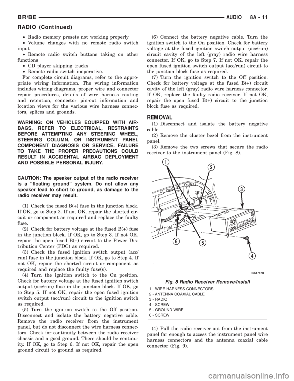
receiver to the instrument panel (Fig. 8).
(4) Pull the radio receiver out from the instrument
panel far enough to access the instrument panel wire
harness connectors and the antenna coaxial cable
connector (Fig. 9).
Fig. 8 Radio Receiver Remove/Install
1 - WIRE HARNESS CONNECTORS
2 - ANTENNA COAXIAL CABLE
3 - RADIO
4 - SCREW
5 - GROUND WIRE
6 - SCREW
BR/BEAUDIO 8A - 11
RADIO (Continued)
Page 435 of 2889
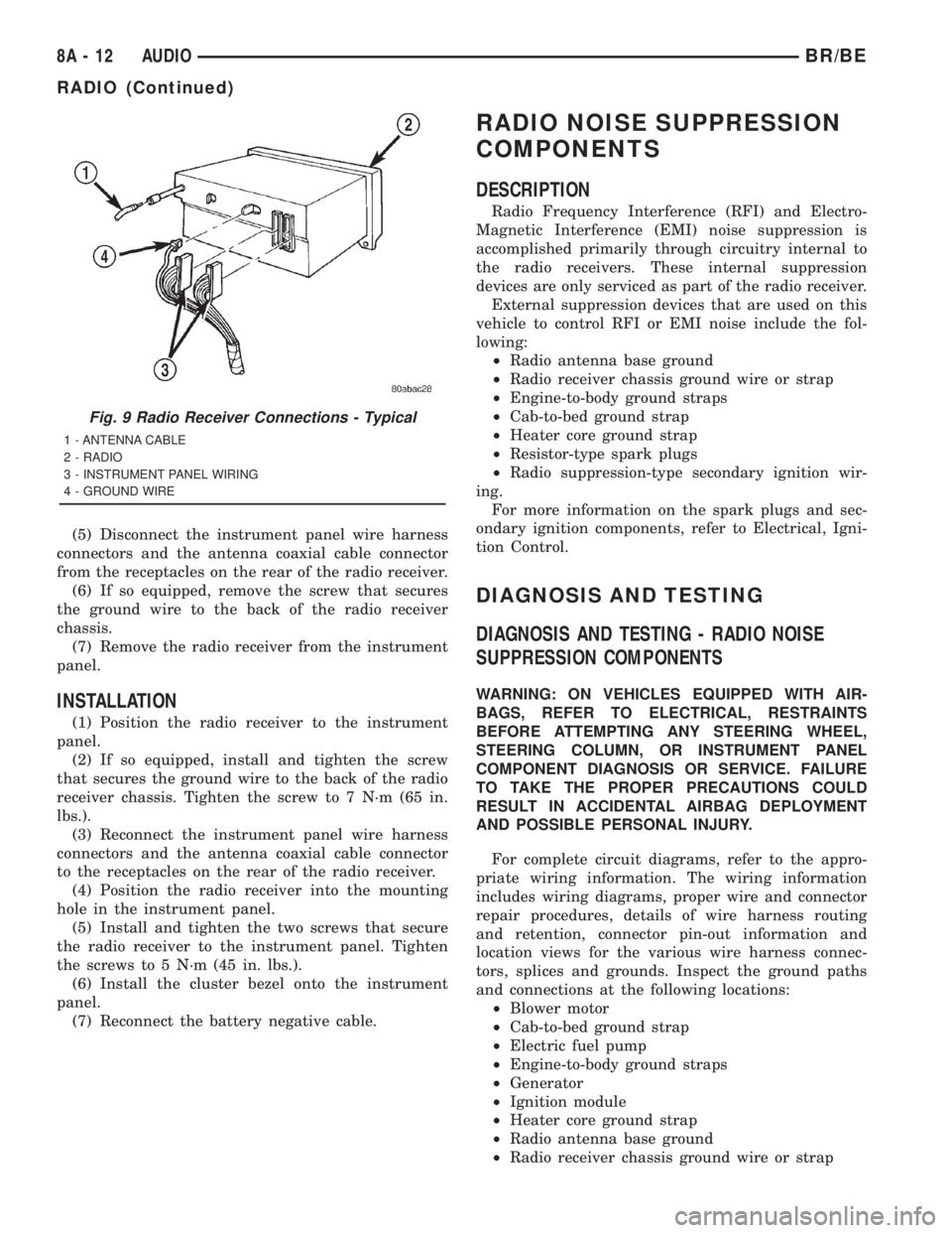
(5) Disconnect the instrument panel wire harness
connectors and the antenna coaxial cable connector
from the receptacles on the rear of the radio receiver.
(6) If so equipped, remove the screw that secures
the ground wire to the back of the radio receiver
chassis.
(7) Remove the radio receiver from the instrument
panel.
INSTALLATION
(1) Position the radio receiver to the instrument
panel.
(2) If so equipped, install and tighten the screw
that secures the ground wire to the back of the radio
receiver chassis. Tighten the screw to 7 N´m (65 in.
lbs.).
(3) Reconnect the instrument panel wire harness
connectors and the antenna coaxial cable connector
to the receptacles on the rear of the radio receiver.
(4) Position the radio receiver into the mounting
hole in the instrument panel.
(5) Install and tighten the two screws that secure
the radio receiver to the instrument panel. Tighten
the screws to 5 N´m (45 in. lbs.).
(6) Install the cluster bezel onto the instrument
panel.
(7) Reconnect the battery negative cable.
RADIO NOISE SUPPRESSION
COMPONENTS
DESCRIPTION
Radio Frequency Interference (RFI) and Electro-
Magnetic Interference (EMI) noise suppression is
accomplished primarily through circuitry internal to
the radio receivers. These internal suppression
devices are only serviced as part of the radio receiver.
External suppression devices that are used on this
vehicle to control RFI or EMI noise include the fol-
lowing:
²Radio antenna base ground
²Radio receiver chassis ground wire or strap
²Engine-to-body ground straps
²Cab-to-bed ground strap
²Heater core ground strap
²Resistor-type spark plugs
²Radio suppression-type secondary ignition wir-
ing.
For more information on the spark plugs and sec-
ondary ignition components, refer to Electrical, Igni-
tion Control.
DIAGNOSIS AND TESTING
DIAGNOSIS AND TESTING - RADIO NOISE
SUPPRESSION COMPONENTS
WARNING: ON VEHICLES EQUIPPED WITH AIR-
BAGS, REFER TO ELECTRICAL, RESTRAINTS
BEFORE ATTEMPTING ANY STEERING WHEEL,
STEERING COLUMN, OR INSTRUMENT PANEL
COMPONENT DIAGNOSIS OR SERVICE. FAILURE
TO TAKE THE PROPER PRECAUTIONS COULD
RESULT IN ACCIDENTAL AIRBAG DEPLOYMENT
AND POSSIBLE PERSONAL INJURY.
For complete circuit diagrams, refer to the appro-
priate wiring information. The wiring information
includes wiring diagrams, proper wire and connector
repair procedures, details of wire harness routing
and retention, connector pin-out information and
location views for the various wire harness connec-
tors, splices and grounds. Inspect the ground paths
and connections at the following locations:
²Blower motor
²Cab-to-bed ground strap
²Electric fuel pump
²Engine-to-body ground straps
²Generator
²Ignition module
²Heater core ground strap
²Radio antenna base ground
²Radio receiver chassis ground wire or strap
Fig. 9 Radio Receiver Connections - Typical
1 - ANTENNA CABLE
2 - RADIO
3 - INSTRUMENT PANEL WIRING
4 - GROUND WIRE
8A - 12 AUDIOBR/BE
RADIO (Continued)
Page 439 of 2889
manual in the vehicle glove box. For complete circuit
diagrams, refer to the appropriate wiring informa-
tion. The wiring information includes wiring dia-
grams, proper wire and connector repair procedures,
details of wire harness routing and retention, connec-
tor pin-out information and location views for the
various wire harness connectors, splices and grounds.
DIAGNOSIS AND TESTING
DIAGNOSIS AND TESTING - REMOTE
SWITCHES
For complete circuit diagrams, refer to the appro-
priate wiring information. The wiring information
includes wiring diagrams, proper wire and connector
repair procedures, details of wire harness routing
and retention, connector pin-out information and
location views for the various wire harness connec-
tors, splices and grounds.
WARNING: ON VEHICLES EQUIPPED WITH AIR-
BAGS, REFER TO ELECTRICAL, RESTRAINTS
BEFORE ATTEMPTING ANY STEERING WHEEL,
STEERING COLUMN, OR INSTRUMENT PANEL
COMPONENT DIAGNOSIS OR SERVICE. FAILURE
TO TAKE THE PROPER PRECAUTIONS COULD
RESULT IN ACCIDENTAL AIRBAG DEPLOYMENT
AND POSSIBLE PERSONAL INJURY.
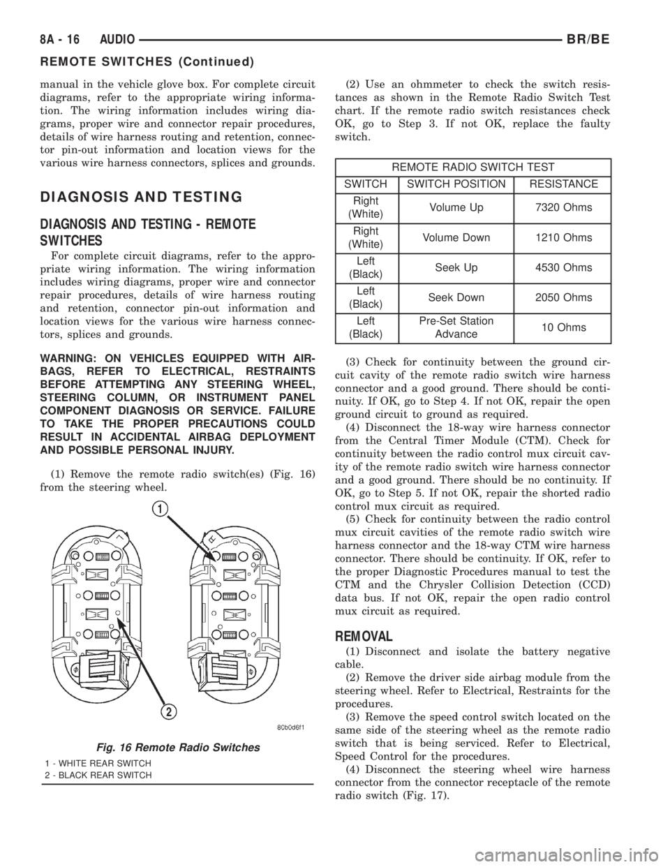
(1) Remove the remote radio switch(es) (Fig. 16)
from the steering wheel.(2) Use an ohmmeter to check the switch resis-
tances as shown in the Remote Radio Switch Test
chart. If the remote radio switch resistances check
OK, go to Step 3. If not OK, replace the faulty
switch.
REMOTE RADIO SWITCH TEST
SWITCH SWITCH POSITION RESISTANCE
Right
(White)Volume Up 7320 Ohms
Right
(White)Volume Down 1210 Ohms
Left
(Black)Seek Up 4530 Ohms
Left
(Black)Seek Down 2050 Ohms
Left
(Black)Pre-Set Station
Advance10 Ohms
(3) Check for continuity between the ground cir-
cuit cavity of the remote radio switch wire harness
connector and a good ground. There should be conti-
nuity. If OK, go to Step 4. If not OK, repair the open
ground circuit to ground as required.
(4) Disconnect the 18-way wire harness connector
from the Central Timer Module (CTM). Check for
continuity between the radio control mux circuit cav-
ity of the remote radio switch wire harness connector
and a good ground. There should be no continuity. If
OK, go to Step 5. If not OK, repair the shorted radio
control mux circuit as required.
(5) Check for continuity between the radio control
mux circuit cavities of the remote radio switch wire
harness connector and the 18-way CTM wire harness
connector. There should be continuity. If OK, refer to
the proper Diagnostic Procedures manual to test the
CTM and the Chrysler Collision Detection (CCD)
data bus. If not OK, repair the open radio control
mux circuit as required.
REMOVAL
(1) Disconnect and isolate the battery negative
cable.
(2) Remove the driver side airbag module from the
steering wheel. Refer to Electrical, Restraints for the
procedures.
(3) Remove the speed control switch located on the
same side of the steering wheel as the remote radio
switch that is being serviced. Refer to Electrical,
Speed Control for the procedures.
(4) Disconnect the steering wheel wire harness
connector from the connector receptacle of the remote
radio switch (Fig. 17).
Fig. 16 Remote Radio Switches
1 - WHITE REAR SWITCH
2 - BLACK REAR SWITCH
8A - 16 AUDIOBR/BE
REMOTE SWITCHES (Continued)
Page 441 of 2889
PREMIUM
The Infinity speakers used in the premium speaker
system are driven by dual amplifiers that are inte-
gral to each of the front door speakers. One of these
dual amplifiers drives the front door speaker and the
A-pillar mounted tweeter for that side of the vehicle,
while the other amplifier drives the rear speaker for
that side of the vehicle. For complete circuit dia-
grams, to refer to the appropriate wiring information.
The wiring information includes wiring diagrams,
proper wire and connector repair procedures, details
of wire harness routing and retention, connector pin-
out information and location views for the various
wire harness connectors, splices and grounds.
DIAGNOSIS AND TESTING - SPEAKER
For complete circuit diagrams, refer to the appro-
priate wiring information. The wiring information
includes wiring diagrams, proper wire and connector
repair procedures, details of wire harness routing
and retention, connector pin-out information and
location views for the various wire harness connec-
tors, splices and grounds.
WARNING: ON VEHICLES EQUIPPED WITH AIR-
BAGS, REFER TO ELECTRICAL, RESTRAINTS
BEFORE ATTEMPTING ANY STEERING WHEEL,
STEERING COLUMN, OR INSTRUMENT PANEL
COMPONENT DIAGNOSIS OR SERVICE. FAILURE
TO TAKE THE PROPER PRECAUTIONS COULD
RESULT IN ACCIDENTAL AIRBAG DEPLOYMENT
AND POSSIBLE PERSONAL INJURY.
CAUTION: The speaker output of the radio receiver
is a ªfloating groundº system. Do not allow any
speaker lead to short to ground, as damage to the
radio receiver may result.
(1) Turn the ignition switch to the On position.
Turn the radio receiver on. Adjust the balance and
fader controls to check the performance of each indi-
vidual speaker. Note the speaker locations that are
not performing correctly. If only an Infinity A-pillar
or an Infinity rear speaker is inoperative, go to Step
8. If any other speaker is inoperative, go to Step 2.
NOTE: If the vehicle is equipped with the Infinity
premium speaker package and all of the speakers
are inoperative, refer to Filter, Choke, and Speaker
Relay in the Diagnosis and Testing section of this
group.
(2) Turn the radio receiver off. Turn the ignition
switch to the Off position. Disconnect and isolate the
battery negative cable. Remove the radio receiver
from the instrument panel. Check both the feed (+)circuit and return (±) circuit cavities for the inopera-
tive speaker location(s) in the radio receiver wire
harness connectors for continuity to ground. In each
case, there should be no continuity. If OK, go to Step
3. If not OK, repair the shorted speaker feed (+)
and/or return (±) circuit(s) to the speaker as required.
(3) If the inoperative speaker is an Infinity-ampli-
fied speaker, go to Step 5. If the vehicle is equipped
with the standard speaker system, check the resis-
tance between the speaker feed (+) circuit and return
(±) circuit cavities of the radio receiver wire harness
connectors for the inoperative speaker location(s).
The meter should read between 2.5 and 4 ohms
(speaker resistance). If OK, go to Step 4. If not OK,
go to Step 5.
(4) Install a known good radio receiver. Connect
the battery negative cable. Turn the ignition switch
to the On position. Turn on the radio receiver and
test the speaker operation. If OK, replace the faulty
radio receiver. If not OK, turn the radio receiver off,
turn the ignition switch to the Off position, discon-
nect and isolate the battery negative cable, remove
the test radio receiver, and go to Step 5.
(5) Disconnect the wire harness connector at the
inoperative standard speaker system speaker or at
the Infinity-amplified front door-mounted speaker.
Check for continuity between the speaker feed (+) cir-
cuit cavities of the radio receiver wire harness con-
nector and the speaker wire harness connector for
the inoperative speaker location. Repeat the check
between the speaker return (±) circuit cavities of the
radio receiver wire harness connector and the
speaker wire harness connector for the inoperative
speaker location. In each case, there should be conti-
nuity. If OK with an Infinity-amplified front door-
mounted speaker, go to Step 6. If OK with the
standard speaker system, replace the faulty speaker.
If not OK, repair the open speaker feed (+) and/or
return (±) circuit(s) as required.
(6) Check for continuity between the ground cir-
cuit cavity in the body half of the wire harness con-
nector for the Infinity-amplified front door-mounted
speaker on the same side of the vehicle as the inop-
erative speaker and a good ground. There should be
continuity. If OK, go to Step 7. If not OK, repair the
open ground circuit to ground as required.
(7) Install the radio receiver. Connect the battery
negative cable. Turn the ignition switch to the On
position. Turn the radio receiver on. Check for bat-
tery voltage at the radio choke output circuit cavity
of the wire harness connector for the Infinity-ampli-
fied front door-mounted speaker on the same side of
the vehicle as the inoperative speaker. If OK, go to
Step 8. If not OK, repair the open radio choke output
circuit to the filter, choke, and speaker relay as
required.
8A - 18 AUDIOBR/BE
SPEAKER (Continued)