Temperature sensor DODGE RAM 2001 Service Manual PDF
[x] Cancel search | Manufacturer: DODGE, Model Year: 2001, Model line: RAM, Model: DODGE RAM 2001Pages: 2889, PDF Size: 68.07 MB
Page 1095 of 2889
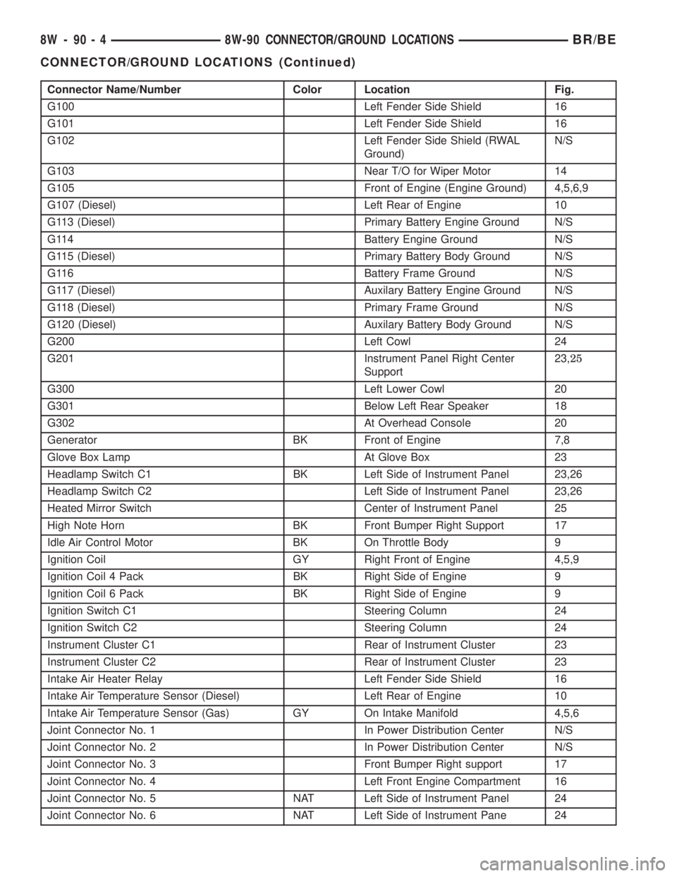
Connector Name/Number Color Location Fig.
G100 Left Fender Side Shield 16
G101 Left Fender Side Shield 16
G102 Left Fender Side Shield (RWAL
Ground)N/S
G103 Near T/O for Wiper Motor 14
G105 Front of Engine (Engine Ground) 4,5,6,9
G107 (Diesel) Left Rear of Engine 10
G113 (Diesel) Primary Battery Engine Ground N/S
G114 Battery Engine Ground N/S
G115 (Diesel) Primary Battery Body Ground N/S
G116 Battery Frame Ground N/S
G117 (Diesel) Auxilary Battery Engine Ground N/S
G118 (Diesel) Primary Frame Ground N/S
G120 (Diesel) Auxilary Battery Body Ground N/S
G200 Left Cowl 24
G201 Instrument Panel Right Center
Support23,25
G300 Left Lower Cowl 20
G301 Below Left Rear Speaker 18
G302 At Overhead Console 20
Generator BK Front of Engine 7,8
Glove Box Lamp At Glove Box 23
Headlamp Switch C1 BK Left Side of Instrument Panel 23,26
Headlamp Switch C2 Left Side of Instrument Panel 23,26
Heated Mirror Switch Center of Instrument Panel 25
High Note Horn BK Front Bumper Right Support 17
Idle Air Control Motor BK On Throttle Body 9
Ignition Coil GY Right Front of Engine 4,5,9
Ignition Coil 4 Pack BK Right Side of Engine 9
Ignition Coil 6 Pack BK Right Side of Engine 9
Ignition Switch C1 Steering Column 24
Ignition Switch C2 Steering Column 24
Instrument Cluster C1 Rear of Instrument Cluster 23
Instrument Cluster C2 Rear of Instrument Cluster 23
Intake Air Heater Relay Left Fender Side Shield 16
Intake Air Temperature Sensor (Diesel) Left Rear of Engine 10
Intake Air Temperature Sensor (Gas) GY On Intake Manifold 4,5,6
Joint Connector No. 1 In Power Distribution Center N/S
Joint Connector No. 2 In Power Distribution Center N/S
Joint Connector No. 3 Front Bumper Right support 17
Joint Connector No. 4 Left Front Engine Compartment 16
Joint Connector No. 5 NAT Left Side of Instrument Panel 24
Joint Connector No. 6 NAT Left Side of Instrument Pane 24
8W - 90 - 4 8W-90 CONNECTOR/GROUND LOCATIONSBR/BE
CONNECTOR/GROUND LOCATIONS (Continued)
Page 1382 of 2889
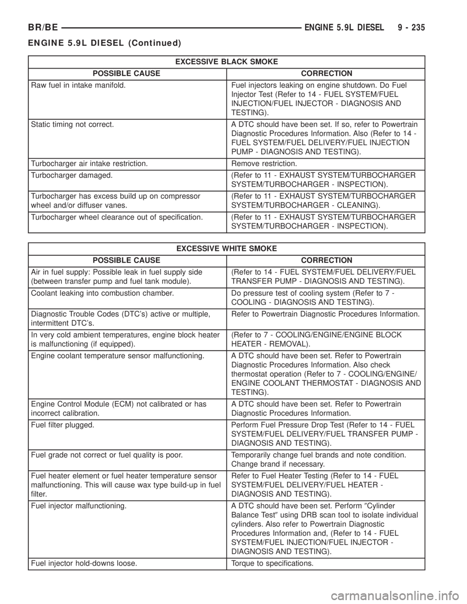
EXCESSIVE BLACK SMOKE
POSSIBLE CAUSE CORRECTION
Raw fuel in intake manifold. Fuel injectors leaking on engine shutdown. Do Fuel
Injector Test (Refer to 14 - FUEL SYSTEM/FUEL
INJECTION/FUEL INJECTOR - DIAGNOSIS AND
TESTING).
Static timing not correct. A DTC should have been set. If so, refer to Powertrain
Diagnostic Procedures Information. Also (Refer to 14 -
FUEL SYSTEM/FUEL DELIVERY/FUEL INJECTION
PUMP - DIAGNOSIS AND TESTING).
Turbocharger air intake restriction. Remove restriction.
Turbocharger damaged. (Refer to 11 - EXHAUST SYSTEM/TURBOCHARGER
SYSTEM/TURBOCHARGER - INSPECTION).
Turbocharger has excess build up on compressor
wheel and/or diffuser vanes.(Refer to 11 - EXHAUST SYSTEM/TURBOCHARGER
SYSTEM/TURBOCHARGER - CLEANING).
Turbocharger wheel clearance out of specification. (Refer to 11 - EXHAUST SYSTEM/TURBOCHARGER
SYSTEM/TURBOCHARGER - INSPECTION).
EXCESSIVE WHITE SMOKE
POSSIBLE CAUSE CORRECTION
Air in fuel supply: Possible leak in fuel supply side
(between transfer pump and fuel tank module).(Refer to 14 - FUEL SYSTEM/FUEL DELIVERY/FUEL
TRANSFER PUMP - DIAGNOSIS AND TESTING).
Coolant leaking into combustion chamber. Do pressure test of cooling system (Refer to 7 -
COOLING - DIAGNOSIS AND TESTING).
Diagnostic Trouble Codes (DTC's) active or multiple,
intermittent DTC's.Refer to Powertrain Diagnostic Procedures Information.
In very cold ambient temperatures, engine block heater
is malfunctioning (if equipped).(Refer to 7 - COOLING/ENGINE/ENGINE BLOCK
HEATER - REMOVAL).
Engine coolant temperature sensor malfunctioning. A DTC should have been set. Refer to Powertrain
Diagnostic Procedures Information. Also check
thermostat operation (Refer to 7 - COOLING/ENGINE/
ENGINE COOLANT THERMOSTAT - DIAGNOSIS AND
TESTING).
Engine Control Module (ECM) not calibrated or has
incorrect calibration.A DTC should have been set. Refer to Powertrain
Diagnostic Procedures Information.
Fuel filter plugged. Perform Fuel Pressure Drop Test (Refer to 14 - FUEL
SYSTEM/FUEL DELIVERY/FUEL TRANSFER PUMP -
DIAGNOSIS AND TESTING).
Fuel grade not correct or fuel quality is poor. Temporarily change fuel brands and note condition.
Change brand if necessary.
Fuel heater element or fuel heater temperature sensor
malfunctioning. This will cause wax type build-up in fuel
filter.Refer to Fuel Heater Testing (Refer to 14 - FUEL
SYSTEM/FUEL DELIVERY/FUEL HEATER -
DIAGNOSIS AND TESTING).
Fuel injector malfunctioning. A DTC should have been set. Perform9Cylinder
Balance Test9using DRB scan tool to isolate individual
cylinders. Also refer to Powertrain Diagnostic
Procedures Information and, (Refer to 14 - FUEL
SYSTEM/FUEL INJECTION/FUEL INJECTOR -
DIAGNOSIS AND TESTING).
Fuel injector hold-downs loose. Torque to specifications.
BR/BEENGINE 5.9L DIESEL 9 - 235
ENGINE 5.9L DIESEL (Continued)
Page 1383 of 2889
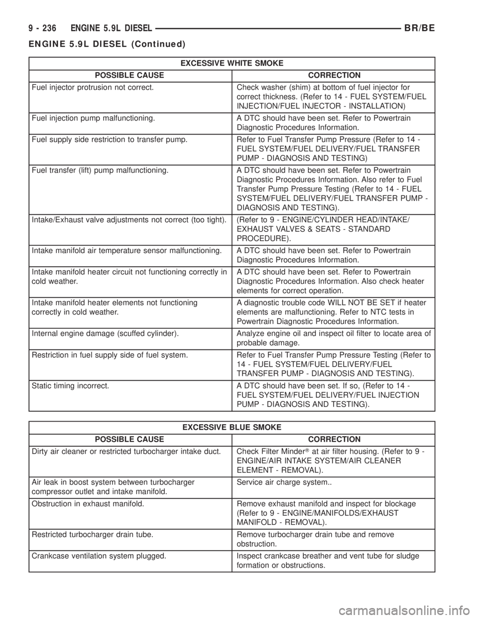
EXCESSIVE WHITE SMOKE
POSSIBLE CAUSE CORRECTION
Fuel injector protrusion not correct. Check washer (shim) at bottom of fuel injector for
correct thickness. (Refer to 14 - FUEL SYSTEM/FUEL
INJECTION/FUEL INJECTOR - INSTALLATION)
Fuel injection pump malfunctioning. A DTC should have been set. Refer to Powertrain
Diagnostic Procedures Information.
Fuel supply side restriction to transfer pump. Refer to Fuel Transfer Pump Pressure (Refer to 14 -
FUEL SYSTEM/FUEL DELIVERY/FUEL TRANSFER
PUMP - DIAGNOSIS AND TESTING)
Fuel transfer (lift) pump malfunctioning. A DTC should have been set. Refer to Powertrain
Diagnostic Procedures Information. Also refer to Fuel
Transfer Pump Pressure Testing (Refer to 14 - FUEL
SYSTEM/FUEL DELIVERY/FUEL TRANSFER PUMP -
DIAGNOSIS AND TESTING).
Intake/Exhaust valve adjustments not correct (too tight). (Refer to 9 - ENGINE/CYLINDER HEAD/INTAKE/
EXHAUST VALVES & SEATS - STANDARD
PROCEDURE).
Intake manifold air temperature sensor malfunctioning. A DTC should have been set. Refer to Powertrain
Diagnostic Procedures Information.
Intake manifold heater circuit not functioning correctly in
cold weather.A DTC should have been set. Refer to Powertrain
Diagnostic Procedures Information. Also check heater
elements for correct operation.
Intake manifold heater elements not functioning
correctly in cold weather.A diagnostic trouble code WILL NOT BE SET if heater
elements are malfunctioning. Refer to NTC tests in
Powertrain Diagnostic Procedures Information.
Internal engine damage (scuffed cylinder). Analyze engine oil and inspect oil filter to locate area of
probable damage.
Restriction in fuel supply side of fuel system. Refer to Fuel Transfer Pump Pressure Testing (Refer to
14 - FUEL SYSTEM/FUEL DELIVERY/FUEL
TRANSFER PUMP - DIAGNOSIS AND TESTING).
Static timing incorrect. A DTC should have been set. If so, (Refer to 14 -
FUEL SYSTEM/FUEL DELIVERY/FUEL INJECTION
PUMP - DIAGNOSIS AND TESTING).
EXCESSIVE BLUE SMOKE
POSSIBLE CAUSE CORRECTION
Dirty air cleaner or restricted turbocharger intake duct. Check Filter MinderTat air filter housing. (Refer to 9 -
ENGINE/AIR INTAKE SYSTEM/AIR CLEANER
ELEMENT - REMOVAL).
Air leak in boost system between turbocharger
compressor outlet and intake manifold.Service air charge system..
Obstruction in exhaust manifold. Remove exhaust manifold and inspect for blockage
(Refer to 9 - ENGINE/MANIFOLDS/EXHAUST
MANIFOLD - REMOVAL).
Restricted turbocharger drain tube. Remove turbocharger drain tube and remove
obstruction.
Crankcase ventilation system plugged. Inspect crankcase breather and vent tube for sludge
formation or obstructions.
9 - 236 ENGINE 5.9L DIESELBR/BE
ENGINE 5.9L DIESEL (Continued)
Page 1393 of 2889
CYLINDER HEAD
DESCRIPTION
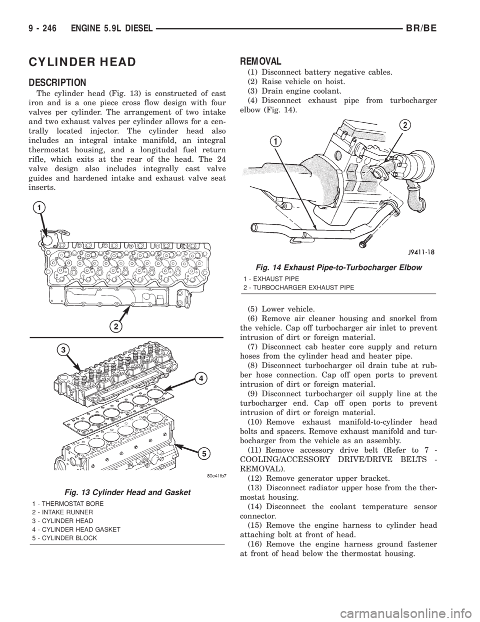
The cylinder head (Fig. 13) is constructed of cast
iron and is a one piece cross flow design with four
valves per cylinder. The arrangement of two intake
and two exhaust valves per cylinder allows for a cen-
trally located injector. The cylinder head also
includes an integral intake manifold, an integral
thermostat housing, and a longitudal fuel return
rifle, which exits at the rear of the head. The 24
valve design also includes integrally cast valve
guides and hardened intake and exhaust valve seat
inserts.
REMOVAL
(1) Disconnect battery negative cables.
(2) Raise vehicle on hoist.
(3) Drain engine coolant.
(4) Disconnect exhaust pipe from turbocharger
elbow (Fig. 14).
(5) Lower vehicle.
(6) Remove air cleaner housing and snorkel from
the vehicle. Cap off turbocharger air inlet to prevent
intrusion of dirt or foreign material.
(7) Disconnect cab heater core supply and return
hoses from the cylinder head and heater pipe.
(8) Disconnect turbocharger oil drain tube at rub-
ber hose connection. Cap off open ports to prevent
intrusion of dirt or foreign material.
(9) Disconnect turbocharger oil supply line at the
turbocharger end. Cap off open ports to prevent
intrusion of dirt or foreign material.
(10) Remove exhaust manifold-to-cylinder head
bolts and spacers. Remove exhaust manifold and tur-
bocharger from the vehicle as an assembly.
(11) Remove accessory drive belt (Refer to 7 -
COOLING/ACCESSORY DRIVE/DRIVE BELTS -
REMOVAL).
(12) Remove generator upper bracket.
(13) Disconnect radiator upper hose from the ther-
mostat housing.
(14) Disconnect the coolant temperature sensor
connector.
(15) Remove the engine harness to cylinder head
attaching bolt at front of head.
(16) Remove the engine harness ground fastener
at front of head below the thermostat housing.
Fig. 13 Cylinder Head and Gasket
1 - THERMOSTAT BORE
2 - INTAKE RUNNER
3 - CYLINDER HEAD
4 - CYLINDER HEAD GASKET
5 - CYLINDER BLOCK
Fig. 14 Exhaust Pipe-to-Turbocharger Elbow
1 - EXHAUST PIPE
2 - TURBOCHARGER EXHAUST PIPE
9 - 246 ENGINE 5.9L DIESELBR/BE
Page 1395 of 2889
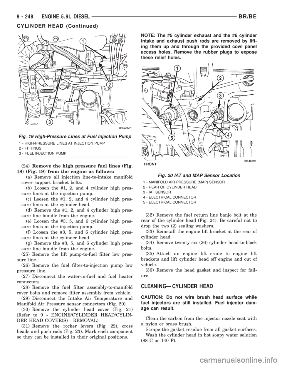
(24)Remove the high pressure fuel lines (Fig.
18) (Fig. 19) from the engine as follows:
(a) Remove all injection line-to-intake manifold
cover support bracket bolts.
(b) Loosen the #1, 2, and 4 cylinder high pres-
sure lines at the injection pump.
(c) Loosen the #1, 2, and 4 cylinder high pres-
sure lines at the cylinder head.
(d) Remove the #1, 2, and 4 cylinder high pres-
sure line bundle from the engine.
(e) Loosen the #3, 5, and 6 cylinder high pres-
sure lines at the injection pump.
(f) Loosen the #3, 5, and 6 cylinder high pres-
sure lines at the cylinder head.
(g) Remove the #3, 5, and 6 cylinder high pres-
sure line bundle from the engine.
(25) Remove the lift pump-to-fuel filter low pres-
sure line.
(26) Remove the fuel filter-to-injection pump low
pressure line.
(27) Disconnect the water-in-fuel and fuel heater
connectors.
(28) Remove the fuel filter assembly-to-manifold
cover bolts and remove filter assembly from vehicle.
(29) Disconnect the Intake Air Temperature and
Manifold Air Pressure sensor connectors (Fig. 20).
(30) Remove the cylinder head cover (Fig. 21)
(Refer to 9 - ENGINE/CYLINDER HEAD/CYLIN-
DER HEAD COVER(S) - REMOVAL).
(31) Remove the rocker levers (Fig. 22), cross
heads and push rods (Fig. 23). Mark each component
so they can be installed in their original positions.NOTE: The #5 cylinder exhaust and the #6 cylinder
intake and exhaust push rods are removed by lift-
ing them up and through the provided cowl panel
access holes. Remove the rubber plugs to expose
these relief holes.
(32) Remove the fuel return line banjo bolt at the
rear of the cylinder head (Fig. 24). Be careful not to
drop the two (2) sealing washers.
(33) Reinstall the engine lift bracket at the rear of
cylinder head.
(34) Remove twenty six (26) cylinder head-to-block
bolts.
(35) Attach an engine lift crane to engine lift
brackets and lift cylinder head off engine and out of
vehicle.
(36) Remove the head gasket and inspect for fail-
ure.
CLEANINGÐCYLINDER HEAD
CAUTION: Do not wire brush head surface while
fuel injectors are still installed. Fuel injector dam-
age can result.
Clean the carbon from the injector nozzle seat with
a nylon or brass brush.
Scrape the gasket residue from all gasket surfaces.
Wash the cylinder head in hot soapy water solution
(88ÉC or 140ÉF).
Fig. 19 High-Pressure Lines at Fuel Injection Pump
1 - HIGH-PRESSURE LINES AT INJECTION PUMP
2 - FITTINGS
3 - FUEL INJECTION PUMP
Fig. 20 IAT and MAP Sensor Location
1 - MANIFOLD AIR PRESSURE (MAP) SENSOR
2 - REAR OF CYLINDER HEAD
3 - IAT SENSOR
4 - ELECTRICAL CONNECTOR
5 - ELECTRICAL CONNECTOR
9 - 248 ENGINE 5.9L DIESELBR/BE
CYLINDER HEAD (Continued)
Page 1399 of 2889
(e) Install the front line bundle (cyls. #1, 2, and
4) following the same procedure used for the rear
line bundle.
(f) Torque the connections at the cylinder head
first. Torque connections to 38 N´m (28 ft. lbs.).
(g) Torque the line connections at the injection
pump to 24 N´m (18 ft. lbs.).
(h) Install the injection line support bracket to
intake cover/cylinder head bolts and torque to 24
N´m (18 ft. lbs.).
(16) Install the engine lift bracket at the rear of
cylinder head. Torque to 77 N´m (57 ft. lbs.).
(17) Install the fuel filter to injection pump low
pressure line. Inspect and replace sealing washers if
necessary. Torque banjo bolts to 24 N´m (18 ft. lbs.).
(18) Using new gaskets, install the intake grid
heater and air inlet housing. Torque bolts to 24 N´m
(18 ft. lbs.).
(19) Connect the APPS connector (Fig. 17).
(20) Install the APPS assembly. to the cylinder
head bracket and torque bolts to 12 N´m (105 in.
lbs.).
(21) Install the throttle linkage cover (Fig. 15).
(22) Install the charge air cooler-to-air inlet hous-
ing duct assembly. Torque all clamps to 11 N´m (100
in. lbs.).
(23) Connect intake grid heater wires.
(24) Fasten engine harness to front of cylinder
head with bolt.
(25) Install engine harness ground wire and torque
bolt to 24 N´m (18 ft. lbs.).
(26) Connect engine coolant temperature sensor
connector.
(27) Connect radiator upper hose to thermostat
housing.
(28) Install generator upper bracket and torque
bolts to 41 N´m (31 ft. lbs.).
(29) Install accessory drive belt (Refer to 7 -
COOLING/ACCESSORY DRIVE/DRIVE BELTS -
INSTALLATION).
(30) Install exhaust manifold/turbocharger assem-
bly. and start all bolts/spacers by hand. Torque bolts
to 43 N´m (32 ft. lbs.).
(31) Connect turbocharger oil drain tube.
(32) Perform the turbocharger pre-lube procedure.
Refer to Group 11, Exhaust System and Turbo-
charger for the correct procedure.
(33) Connect the turbocharger oil supply line.
(34) Install air cleaner housing and duct.
(35) Raise vehicle on hoist.
(36) Install exhaust pipe to turbocharger elbow
(Fig. 14). Torque bolts to 34 N´m (25 ft. lbs.).
(37) Lower vehicle.
(38) Fill engine coolant (Refer to 7 - COOLING -
STANDARD PROCEDURE).
(39) Start engine and check for leaks.
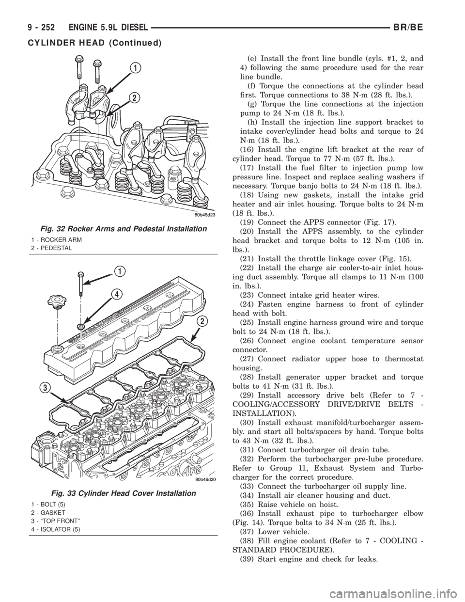
Fig. 32 Rocker Arms and Pedestal Installation
1 - ROCKER ARM
2 - PEDESTAL
Fig. 33 Cylinder Head Cover Installation
1 - BOLT (5)
2 - GASKET
3 - ªTOP FRONTº
4 - ISOLATOR (5)
9 - 252 ENGINE 5.9L DIESELBR/BE
CYLINDER HEAD (Continued)
Page 1504 of 2889
(7) 3.9L (V-6) engine only: Disconnect electrical
connector at intake manifold air temperature sensor.
Do not remove sensor.
(8) Disconnect fuel tube (line) at side of fuel rail.
Refer to Quick-Connect Fittings for procedures,
(9) Remove the remaining fuel rail mounting bolts.
(10) Gently rock and pull theleftfuel rail until
the fuel injectors just start to clear the intake mani-
fold. Gently rock and pull therightfuel rail until
the fuel injectors just start to clear the intake mani-
fold. Repeat this procedure (left/right) until all fuel
injectors have cleared the intake manifold.
(11) Remove fuel rail (with injectors attached)
from engine.
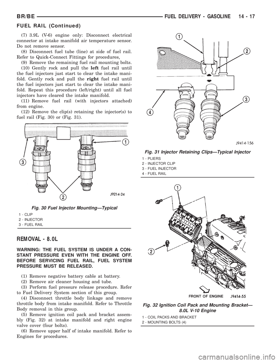
(12) Remove the clip(s) retaining the injector(s) to
fuel rail (Fig. 30) or (Fig. 31).
REMOVAL - 8.0L
WARNING: THE FUEL SYSTEM IS UNDER A CON-
STANT PRESSURE EVEN WITH THE ENGINE OFF.
BEFORE SERVICING FUEL RAIL, FUEL SYSTEM
PRESSURE MUST BE RELEASED.
(1) Remove negative battery cable at battery.
(2) Remove air cleaner housing and tube.
(3) Perform fuel pressure release procedure. Refer
to Fuel Delivery System section of this group.
(4) Disconnect throttle body linkage and remove
throttle body from intake manifold. Refer to Throttle
Body removal in this group.
(5) Remove ignition coil pack and bracket assem-
bly (Fig. 32) at intake manifold and right engine
valve cover (four bolts).
(6) Remove upper half of intake manifold. Refer to
Engines for procedures.
Fig. 30 Fuel Injector MountingÐTypical
1 - CLIP
2 - INJECTOR
3 - FUEL RAIL
Fig. 31 Injector Retaining ClipsÐTypical Injector
1 - PLIERS
2 - INJECTOR CLIP
3 - FUEL INJECTOR
4 - FUEL RAIL
Fig. 32 Ignition Coil Pack and Mounting BracketÐ
8.0L V-10 Engine
1 - COIL PACKS AND BRACKET
2 - MOUNTING BOLTS (4)
BR/BEFUEL DELIVERY - GASOLINE 14 - 17
FUEL RAIL (Continued)
Page 1505 of 2889
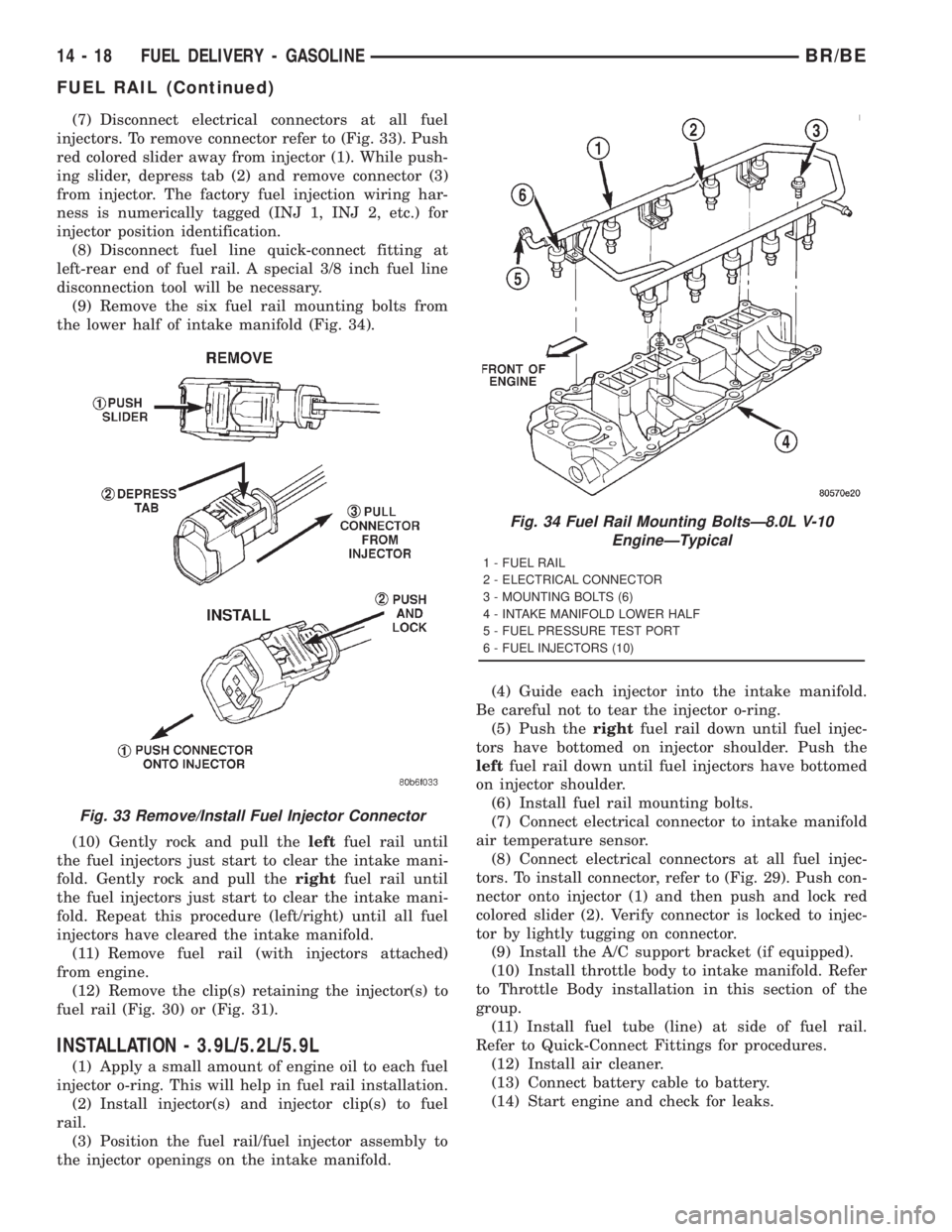
(7) Disconnect electrical connectors at all fuel
injectors. To remove connector refer to (Fig. 33). Push
red colored slider away from injector (1). While push-
ing slider, depress tab (2) and remove connector (3)
from injector. The factory fuel injection wiring har-
ness is numerically tagged (INJ 1, INJ 2, etc.) for
injector position identification.
(8) Disconnect fuel line quick-connect fitting at
left-rear end of fuel rail. A special 3/8 inch fuel line
disconnection tool will be necessary.
(9) Remove the six fuel rail mounting bolts from
the lower half of intake manifold (Fig. 34).
(10) Gently rock and pull theleftfuel rail until
the fuel injectors just start to clear the intake mani-
fold. Gently rock and pull therightfuel rail until
the fuel injectors just start to clear the intake mani-
fold. Repeat this procedure (left/right) until all fuel
injectors have cleared the intake manifold.
(11) Remove fuel rail (with injectors attached)
from engine.
(12) Remove the clip(s) retaining the injector(s) to
fuel rail (Fig. 30) or (Fig. 31).
INSTALLATION - 3.9L/5.2L/5.9L
(1) Apply a small amount of engine oil to each fuel
injector o-ring. This will help in fuel rail installation.
(2) Install injector(s) and injector clip(s) to fuel
rail.
(3) Position the fuel rail/fuel injector assembly to
the injector openings on the intake manifold.(4) Guide each injector into the intake manifold.
Be careful not to tear the injector o-ring.
(5) Push therightfuel rail down until fuel injec-
tors have bottomed on injector shoulder. Push the
leftfuel rail down until fuel injectors have bottomed
on injector shoulder.
(6) Install fuel rail mounting bolts.
(7) Connect electrical connector to intake manifold
air temperature sensor.
(8) Connect electrical connectors at all fuel injec-
tors. To install connector, refer to (Fig. 29). Push con-
nector onto injector (1) and then push and lock red
colored slider (2). Verify connector is locked to injec-
tor by lightly tugging on connector.
(9) Install the A/C support bracket (if equipped).
(10) Install throttle body to intake manifold. Refer
to Throttle Body installation in this section of the
group.
(11) Install fuel tube (line) at side of fuel rail.
Refer to Quick-Connect Fittings for procedures.
(12) Install air cleaner.
(13) Connect battery cable to battery.
(14) Start engine and check for leaks.
Fig. 33 Remove/Install Fuel Injector Connector
Fig. 34 Fuel Rail Mounting BoltsÐ8.0L V-10
EngineÐTypical
1 - FUEL RAIL
2 - ELECTRICAL CONNECTOR
3 - MOUNTING BOLTS (6)
4 - INTAKE MANIFOLD LOWER HALF
5 - FUEL PRESSURE TEST PORT
6 - FUEL INJECTORS (10)
14 - 18 FUEL DELIVERY - GASOLINEBR/BE
FUEL RAIL (Continued)
Page 1515 of 2889
FUEL INJECTION - GASOLINE
TABLE OF CONTENTS
page page
FUEL INJECTION - GASOLINE
DIAGNOSIS AND TESTING.................28
VISUAL INSPECTION - 3.9L/5.2L/5.9L
ENGINES.............................28
VISUAL INSPECTION - 8.0L ENGINE........32
SPECIFICATIONS........................35
SPECIAL TOOLS.........................36
ACCELERATOR PEDAL
REMOVAL..............................37
INSTALLATION...........................37
CRANKSHAFT POSITION SENSOR
DESCRIPTION...........................38
OPERATION.............................38
REMOVAL..............................39
INSTALLATION...........................40
FUEL PUMP RELAY
DESCRIPTION...........................41
OPERATION.............................41
REMOVAL..............................41
INSTALLATION...........................41
IDLE AIR CONTROL MOTOR
DESCRIPTION...........................41
OPERATION.............................41
REMOVAL..............................42
INSTALLATION...........................42
INTAKE AIR TEMPERATURE SENSOR
DESCRIPTION...........................43
OPERATION.............................43
REMOVAL..............................43
INSTALLATION...........................43
MANIFOLD ABSOLUTE PRESSURE SENSOR
DESCRIPTION...........................44OPERATION.............................44
REMOVAL..............................45
INSTALLATION...........................45
O2 SENSOR
DESCRIPTION...........................46
OPERATION.............................46
REMOVAL..............................47
INSTALLATION...........................48
PTO SWITCH
DESCRIPTION...........................48
OPERATION.............................48
THROTTLE BODY
DESCRIPTION...........................48
OPERATION.............................48
REMOVAL..............................48
INSTALLATION...........................49
THROTTLE CONTROL CABLE
REMOVAL..............................50
INSTALLATION...........................50
THROTTLE POSITION SENSOR
DESCRIPTION...........................51
OPERATION.............................51
REMOVAL..............................51
INSTALLATION...........................52
FUEL INJECTOR
DESCRIPTION...........................53
OPERATION.............................53
DIAGNOSIS AND TESTING.................53
FUEL INJECTOR TEST...................53
REMOVAL..............................53
INSTALLATION...........................53
FUEL INJECTION - GASOLINE
VISUAL INSPECTIONÐ3.9L/5.2L/5.9L
ENGINES
A visual inspection for loose, disconnected or incor-
rectly routed wires and hoses should be made. This
should be done before attempting to diagnose or ser-
vice the fuel injection system. A visual check will
help spot these faults and save unnecessary test and
diagnostic time. A thorough visual inspection will
include the following checks:
(1) Verify that the three 32±way electrical connec-
tors are fully inserted into the connector of the pow-
ertrain control module (PCM) (Fig. 1).(2) Inspect the battery cable connections. Be sure
that they are clean and tight.
(3) Inspect fuel pump relay and air conditioning
compressor clutch relay (if equipped). Inspect the
ASD relay connections. Inspect starter motor relay
connections. Inspect relays for signs of physical dam-
age and corrosion. The relays are located in the
Power Distribution Center (PDC) (Fig. 2). Refer to
label on PDC cover for relay location.
(4) Inspect ignition coil connections. Verify that
coil secondary cable is firmly connected to coil (Fig.
3).
14 - 28 FUEL INJECTION - GASOLINEBR/BE
Page 1517 of 2889
(11) Inspect accelerator cable, transmission throt-
tle cable (if equipped) and cruise control cable con-
nections (if equipped). Check their connections to the
throttle arm of throttle body for any binding or
restrictions.
(12) If equipped with vacuum brake booster, verify
that vacuum booster hose is firmly connected to fit-
ting on intake manifold. Also check connection to
brake vacuum booster.
(13) Inspect the air cleaner inlet and air cleaner
element for dirt or restrictions.
(14) Inspect radiator grille area, radiator fins and
air conditioning condenser for restrictions.
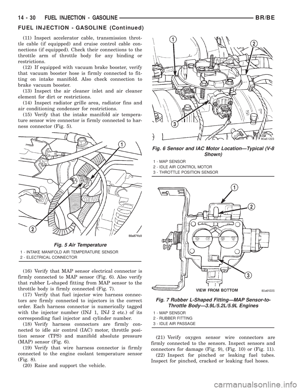
(15) Verify that the intake manifold air tempera-
ture sensor wire connector is firmly connected to har-
ness connector (Fig. 5).
(16) Verify that MAP sensor electrical connector is
firmly connected to MAP sensor (Fig. 6). Also verify
that rubber L-shaped fitting from MAP sensor to the
throttle body is firmly connected (Fig. 7).
(17) Verify that fuel injector wire harness connec-
tors are firmly connected to injectors in the correct
order. Each harness connector is numerically tagged
with the injector number (INJ 1, INJ 2 etc.) of its
corresponding fuel injector and cylinder number.
(18) Verify harness connectors are firmly con-
nected to idle air control (IAC) motor, throttle posi-
tion sensor (TPS) and manifold absolute pressure
(MAP) sensor (Fig. 6).
(19) Verify that wire harness connector is firmly
connected to the engine coolant temperature sensor
(Fig. 8).
(20) Raise and support the vehicle.(21) Verify oxygen sensor wire connectors are
firmly connected to the sensors. Inspect sensors and
connectors for damage (Fig. 9), (Fig. 10) or (Fig. 11).
(22) Inspect for pinched or leaking fuel tubes.
Inspect for pinched, cracked or leaking fuel hoses.
Fig. 5 Air Temperature
1 - INTAKE MANIFOLD AIR TEMPERATURE SENSOR
2 - ELECTRICAL CONNECTOR
Fig. 6 Sensor and IAC Motor LocationÐTypical (V-8
Shown)
1 - MAP SENSOR
2 - IDLE AIR CONTROL MOTOR
3 - THROTTLE POSITION SENSOR
Fig. 7 Rubber L-Shaped FittingÐMAP Sensor-to-
Throttle BodyÐ3.9L/5.2L/5.9L Engines
1 - MAP SENSOR
2 - RUBBER FITTING
3 - IDLE AIR PASSAGE
14 - 30 FUEL INJECTION - GASOLINEBR/BE
FUEL INJECTION - GASOLINE (Continued)